verilog实验37个程序
用verilog编写的反Z变换程序
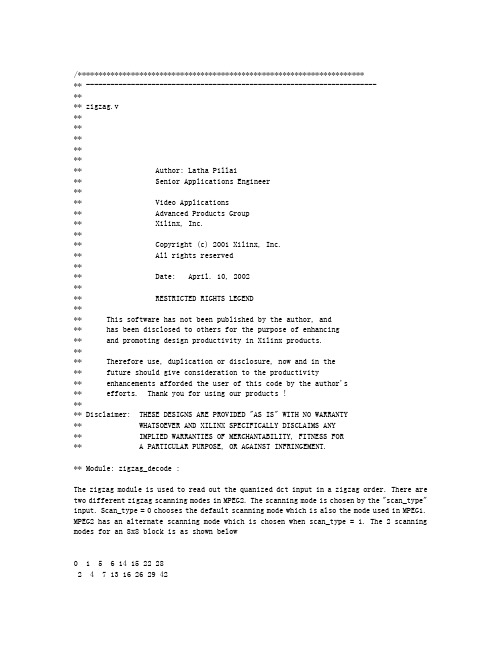
/************************************************************************ -----------------------------------------------------------------------**** zigzag.v************ Author: Latha Pillai** Senior Applications Engineer**** Video Applications** Advanced Products Group** Xilinx, Inc.**** Copyright (c) 2001 Xilinx, Inc.** All rights reserved**** Date: April. 10, 2002**** RESTRICTED RIGHTS LEGEND**** This software has not been published by the author, and** has been disclosed to others for the purpose of enhancing** and promoting design productivity in Xilinx products.**** Therefore use, duplication or disclosure, now and in the** future should give consideration to the productivity** enhancements afforded the user of this code by the author's** efforts. Thank you for using our products !**** Disclaimer: THESE DESIGNS ARE PROVIDED "AS IS" WITH NO WARRANTY** WHATSOEVER AND XILINX SPECIFICALLY DISCLAIMS ANY** IMPLIED WARRANTIES OF MERCHANTABILITY, FITNESS FOR** A PARTICULAR PURPOSE, OR AGAINST INFRINGEMENT.** Module: zigzag_decode :The zigzag module is used to read out the quanized dct input in a zigzag order. There are two different zigzag scanning modes in MPEG2. The scanning mode is chosen by the "scan_type" input. Scan_type = 0 chooses the default scanning mode which is also the mode used in MPEG1. MPEG2 has an alternate scanning mode which is chosen when scan_type = 1. The 2 scanning modes for an 8x8 block is as shown below0 1 5 6 14 15 22 282 4 7 13 16 26 29 423 8 12 17 25 30 41 439 11 18 24 31 40 44 5310 19 23 32 39 45 52 5420 22 33 38 46 51 55 6021 34 37 47 50 56 59 6135 36 48 49 57 58 62 630 4 6 20 22 36 38 521 5 7 21 23 37 39 532 8 19 24 34 40 50 543 9 18 25 35 41 51 5510 17 26 30 42 46 56 6011 16 27 31 43 47 57 6112 15 28 32 44 48 58 6213 14 29 33 45 49 59 63The scanning order requires that some of the later coeeficients be available in the beginning. For example, in alternate scanning mode, the 56th coeeficient is read in at the 13th clock. Also some of the initial coefficients are read out later in the cycle. For example, in alternate scanning mode, the 7th coefficient is read out only in the 52th clock cycle. Due to this nature, it is safer to have all the 64 coefficient available for 64 clock cycles. This is ensured by the memread_rdy signal. This signal waits for 64 clocks before reading out from zigzag_in_reg1. By this time, all the 64 coefficients would have been stored in this memory and they are held there for 64 clocks.Since the input data zigzag_in is continuous, we get a new value for the 1st coefficient at the 65th clock. Since the reading from zigzag_in_reg1 would not be complete by the 65th clock, a second memory , zigzag_in_reg2, is used to store the next set of 64 coefficients. After reading the 64 values from zigzag_in_reg1, the next 64 values are read from zigzag_in_reg2. This selection is done using the toggle_mem signal. This signal holds a '0' or '1' for 64 clocks and then switches.The values are read out from the memories depending on the value of scan_mem. Scan_mem is a register used to hold the 2 different kinds of scanning orders. Scan_type signal chooses between the 2 scanning orders.**********************************************************************///scale factor --- how many bits ?`timescale 1ns/1psmodule zigzag_decode ( CLK,RST,rdy_in,zigzag_in,scan_type,qdct_out);input CLK;input RST;input[11:0] zigzag_in; /* 11 bit output from DCT block */input rdy_in; /* ready signal , starts quantization process after DCT is done for the block */input scan_type; /* used to choose b/n intra(0) & non-intra(1)blocks */output [11:0] qdct_out; /* quantised output value *//* signals */reg[6:0] cnt64;reg memread_rdy;reg toggle_mem;reg[6:0] scan_mem;reg[11:0] zigzag_in_reg1[63:0];reg[11:0] zigzag_in_reg2[63:0];reg[11:0] zigzag_out;/*****************************************************************************//* scan_type register. This register is used to store the 2 different kinds of scan mode.Normal scan mode (0) is used for MPEG1 and MPEG2. Alternate scan mode (1) is used in MPEG2for intra coded blocks */always @ (posedge CLK)beginif (scan_type == 1'b0)begincase (cnt64)1 : begin scan_mem <= 7'd 0; end2 : begin scan_mem <= 7'd 1; end3 : begin scan_mem <= 7'd 8; end4 : begin scan_mem <= 7'd 16; end5 : begin scan_mem <= 7'd 9; end6 : begin scan_mem <= 7'd 2; end7 : begin scan_mem <= 7'd 3; end 8 : begin scan_mem <= 7'd 10; end9 : begin scan_mem <= 7'd 17; end 10 : begin scan_mem <= 7'd 24; end11 : begin scan_mem <= 7'd 32; end 12 : begin scan_mem <= 7'd 25; end13 : begin scan_mem <= 7'd 18; end 14 : begin scan_mem <= 7'd 11; end15 : begin scan_mem <= 7'd 4; end 16 : begin scan_mem <= 7'd 5; end17 : begin scan_mem <= 7'd 12; end 18 : begin scan_mem <= 7'd 19; end19 : begin scan_mem <= 7'd 26; end 20 : begin scan_mem <= 7'd 33; end21 : begin scan_mem <= 7'd 40; end 22 : begin scan_mem <= 7'd 48; end23 : begin scan_mem <= 7'd 41; end 24 : begin scan_mem <= 7'd 34; end25 : begin scan_mem <= 7'd 27; end 26 : begin scan_mem <= 7'd 20; end27 : begin scan_mem <= 7'd 13; end 28 : begin scan_mem <= 7'd 6; end29 : begin scan_mem <= 7'd 7; end 30 : begin scan_mem <= 7'd 14; end31 : begin scan_mem <= 7'd 21; end 32 : begin scan_mem <= 7'd 28; end35 : begin scan_mem <= 7'd 49; end 36 : begin scan_mem <= 7'd 56; end 37 : begin scan_mem <= 7'd 57; end 38 : begin scan_mem <= 7'd 50; end 39 : begin scan_mem <= 7'd 43; end 40 : begin scan_mem <= 7'd 36; end 41 : begin scan_mem <= 7'd 29; end 42 : begin scan_mem <= 7'd 22; end 43 : begin scan_mem <= 7'd 15; end 44 : begin scan_mem <= 7'd 23; end 45 : begin scan_mem <= 7'd 30; end 46 : begin scan_mem <= 7'd 37; end 47 : begin scan_mem <= 7'd 44; end 48 : begin scan_mem <= 7'd 51; end 49 : begin scan_mem <= 7'd 58; end 50 : begin scan_mem <= 7'd 59; end 51 : begin scan_mem <= 7'd 52; end 52 : begin scan_mem <= 7'd 45; end 53 : begin scan_mem <= 7'd 38; end 54 : begin scan_mem <= 7'd 31; end 55 : begin scan_mem <= 7'd 27; end 56 : begin scan_mem <= 7'd 46; end 57 : begin scan_mem <= 7'd 53; end 58 : begin scan_mem <= 7'd 60; end 59 : begin scan_mem <= 7'd 61; end 60 : begin scan_mem <= 7'd 54; end 61 : begin scan_mem <= 7'd 47; end 62 : begin scan_mem <= 7'd 55; end 63 : begin scan_mem <= 7'd 62; end 64 : begin scan_mem <= 7'd 63; end endcaseendelse if (scan_type == 1'b1)begincase (cnt64)1 : begin scan_mem <= 7'd 0; end2 : begin scan_mem <= 7'd 8; end3 : begin scan_mem <= 7'd 16; end4 : begin scan_mem <= 7'd 24; end5 : begin scan_mem <= 7'd 1; end6 : begin scan_mem <= 7'd 9; end7 : begin scan_mem <= 7'd 2; end8 : begin scan_mem <= 7'd 10; end9: begin scan_mem <= 7'd 17; end 10 : begin scan_mem <= 7'd 25; end 11 : begin scan_mem <= 7'd 32; end 12 : begin scan_mem <= 7'd 40; end 13 : begin scan_mem <= 7'd 48; end 14 : begin scan_mem <= 7'd 56; end 15 : begin scan_mem <= 7'd 4; end 16 : begin scan_mem <= 7'd 49; end 17 : begin scan_mem <= 7'd 41; end 18 : begin scan_mem <= 7'd 33; end 19 : begin scan_mem <= 7'd 26; end 20 : begin scan_mem <= 7'd 18; end 21 : begin scan_mem <= 7'd 3; end 22 : begin scan_mem <= 7'd 11; end 23 : begin scan_mem <= 7'd 4; end 24 : begin scan_mem <= 7'd 12; end 25 : begin scan_mem <= 7'd 19; end 26 : begin scan_mem <= 7'd 27; end 27 : begin scan_mem <= 7'd 34; end 28 : begin scan_mem <= 7'd 42; end 29 : begin scan_mem <= 7'd 50; end 30 : begin scan_mem <= 7'd 58; end 31 : begin scan_mem <= 7'd 35; end 32 : begin scan_mem <= 7'd 43; end 33 : begin scan_mem <= 7'd 51; end 34 : begin scan_mem <= 7'd 59; end 35 : begin scan_mem <= 7'd 20; end 36 : begin scan_mem <= 7'd 28; end 37 : begin scan_mem <= 7'd 5; end 38 : begin scan_mem <= 7'd 13; end 39 : begin scan_mem <= 7'd 6; end 40 : begin scan_mem <= 7'd 14; end 41 : begin scan_mem <= 7'd 21; end 42 : begin scan_mem <= 7'd 29; end 43 : begin scan_mem <= 7'd 36; end 44 : begin scan_mem <= 7'd 44; end 45 : begin scan_mem <= 7'd 52; end 46 : begin scan_mem <= 7'd 60; end 47 : begin scan_mem <= 7'd 37; end 48 : begin scan_mem <= 7'd 45; end 49 : begin scan_mem <= 7'd 53; end 50 : begin scan_mem <= 7'd 61; end 51 : begin scan_mem <= 7'd 22; end 52 : begin scan_mem <= 7'd 30; end 53 : begin scan_mem <= 7'd 7; end 54 : begin scan_mem <= 7'd 15; end 55 : begin scan_mem <= 7'd 23; end 56 : begin scan_mem <= 7'd 31; end59 : begin scan_mem <= 7'd 54; end 60 : begin scan_mem <= 7'd 62; end61 : begin scan_mem <= 7'd 39; end 62 : begin scan_mem <= 7'd 47; end63 : begin scan_mem <= 7'd 55; end 64 : begin scan_mem <= 7'd 63; endendcaseendend/*****************************************************************************//* zigzag_in_reg1 and zigzag_in_reg2 are used to store the quantised DCT values encoded in zigzag order. Both registers use store the same DCT values. Data from reg1 is read out in the zigzag order and data from reg2 is read out in the alternate scan order */initialbeginzigzag_in_reg1[0] <= 12'b0; zigzag_in_reg1[1] <= 12'b0;zigzag_in_reg1[2] <= 12'b0; zigzag_in_reg1[3] <= 12'b0;zigzag_in_reg1[4] <= 12'b0; zigzag_in_reg1[5] <= 12'b0;zigzag_in_reg1[6] <= 12'b0; zigzag_in_reg1[7] <= 12'b0;zigzag_in_reg1[8] <= 12'b0; zigzag_in_reg1[9] <= 12'b0;zigzag_in_reg1[10] <= 12'b0; zigzag_in_reg1[11] <= 12'b0;zigzag_in_reg1[12] <= 12'b0; zigzag_in_reg1[13] <= 12'b0;zigzag_in_reg1[14] <= 12'b0; zigzag_in_reg1[15] <= 12'b0;zigzag_in_reg1[16] <= 12'b0; zigzag_in_reg1[17] <= 12'b0;zigzag_in_reg1[18] <= 12'b0; zigzag_in_reg1[19] <= 12'b0;zigzag_in_reg1[20] <= 12'b0; zigzag_in_reg1[21] <= 12'b0;zigzag_in_reg1[22] <= 12'b0; zigzag_in_reg1[23] <= 12'b0;zigzag_in_reg1[24] <= 12'b0; zigzag_in_reg1[25] <= 12'b0;zigzag_in_reg1[26] <= 12'b0; zigzag_in_reg1[27] <= 12'b0;zigzag_in_reg1[28] <= 12'b0; zigzag_in_reg1[29] <= 12'b0;zigzag_in_reg1[30] <= 12'b0; zigzag_in_reg1[31] <= 12'b0;zigzag_in_reg1[32] <= 12'b0; zigzag_in_reg1[33] <= 12'b0;zigzag_in_reg1[34] <= 12'b0; zigzag_in_reg1[35] <= 12'b0;zigzag_in_reg1[36] <= 12'b0; zigzag_in_reg1[37] <= 12'b0;zigzag_in_reg1[38] <= 12'b0; zigzag_in_reg1[39] <= 12'b0;zigzag_in_reg1[40] <= 12'b0; zigzag_in_reg1[41] <= 12'b0;zigzag_in_reg1[42] <= 12'b0; zigzag_in_reg1[43] <= 12'b0;zigzag_in_reg1[44] <= 12'b0; zigzag_in_reg1[45] <= 12'b0;zigzag_in_reg1[46] <= 12'b0; zigzag_in_reg1[47] <= 12'b0;zigzag_in_reg1[48] <= 12'b0; zigzag_in_reg1[49] <= 12'b0;zigzag_in_reg1[50] <= 12'b0; zigzag_in_reg1[51] <= 12'b0;zigzag_in_reg1[52] <= 12'b0; zigzag_in_reg1[53] <= 12'b0;zigzag_in_reg1[54] <= 12'b0; zigzag_in_reg1[55] <= 12'b0;zigzag_in_reg1[56] <= 12'b0; zigzag_in_reg1[57] <= 12'b0;zigzag_in_reg1[58] <= 12'b0; zigzag_in_reg1[59] <= 12'b0;zigzag_in_reg1[60] <= 12'b0; zigzag_in_reg1[61] <= 12'b0;zigzag_in_reg1[62] <= 12'b0; zigzag_in_reg1[63] <= 12'b0;zigzag_in_reg2[0] <= 12'b0; zigzag_in_reg2[1] <= 12'b0;zigzag_in_reg2[2] <= 12'b0; zigzag_in_reg2[3] <= 12'b0;zigzag_in_reg2[4] <= 12'b0; zigzag_in_reg2[5] <= 12'b0;zigzag_in_reg2[6] <= 12'b0; zigzag_in_reg2[7] <= 12'b0;zigzag_in_reg2[8] <= 12'b0; zigzag_in_reg2[9] <= 12'b0;zigzag_in_reg2[10] <= 12'b0; zigzag_in_reg2[11] <= 12'b0;zigzag_in_reg2[12] <= 12'b0; zigzag_in_reg2[13] <= 12'b0;zigzag_in_reg2[14] <= 12'b0; zigzag_in_reg2[15] <= 12'b0;zigzag_in_reg2[16] <= 12'b0; zigzag_in_reg2[17] <= 12'b0;zigzag_in_reg2[18] <= 12'b0; zigzag_in_reg2[19] <= 12'b0;zigzag_in_reg2[20] <= 12'b0; zigzag_in_reg2[21] <= 12'b0;zigzag_in_reg2[22] <= 12'b0; zigzag_in_reg2[23] <= 12'b0;zigzag_in_reg2[24] <= 12'b0; zigzag_in_reg2[25] <= 12'b0;zigzag_in_reg2[26] <= 12'b0; zigzag_in_reg2[27] <= 12'b0;zigzag_in_reg2[28] <= 12'b0; zigzag_in_reg2[29] <= 12'b0;zigzag_in_reg2[30] <= 12'b0; zigzag_in_reg2[31] <= 12'b0;zigzag_in_reg2[32] <= 12'b0; zigzag_in_reg2[33] <= 12'b0;zigzag_in_reg2[34] <= 12'b0; zigzag_in_reg2[35] <= 12'b0;zigzag_in_reg2[36] <= 12'b0; zigzag_in_reg2[37] <= 12'b0;zigzag_in_reg2[38] <= 12'b0; zigzag_in_reg2[39] <= 12'b0;zigzag_in_reg2[40] <= 12'b0; zigzag_in_reg2[41] <= 12'b0;zigzag_in_reg2[42] <= 12'b0; zigzag_in_reg2[43] <= 12'b0;zigzag_in_reg2[44] <= 12'b0; zigzag_in_reg2[45] <= 12'b0;zigzag_in_reg2[46] <= 12'b0; zigzag_in_reg2[47] <= 12'b0;zigzag_in_reg2[48] <= 12'b0; zigzag_in_reg2[49] <= 12'b0;zigzag_in_reg2[50] <= 12'b0; zigzag_in_reg2[51] <= 12'b0;zigzag_in_reg2[52] <= 12'b0; zigzag_in_reg2[53] <= 12'b0;zigzag_in_reg2[54] <= 12'b0; zigzag_in_reg2[55] <= 12'b0;zigzag_in_reg2[56] <= 12'b0; zigzag_in_reg2[57] <= 12'b0;zigzag_in_reg2[58] <= 12'b0; zigzag_in_reg2[59] <= 12'b0;zigzag_in_reg2[60] <= 12'b0; zigzag_in_reg2[61] <= 12'b0;zigzag_in_reg2[62] <= 12'b0; zigzag_in_reg2[63] <= 12'b0;end/* store zigzag input in the scan order: pipe1 */always @ (posedge CLK)if (rdy_in == 1'b1 && toggle_mem == 1'b0)zigzag_in_reg1[scan_mem]<= zigzag_in;else if (rdy_in == 1'b1 && toggle_mem == 1'b1)zigzag_in_reg2[scan_mem]<= zigzag_in;/* read out quantised DCT values in the counter 64 order :pipe2*/ always @ (posedge CLK)beginif (memread_rdy == 1'b1 && toggle_mem == 1'b1)qdct_out <= zigzag_in_reg1[cnt64];else if (memread_rdy == 1'b1 && toggle_mem == 1'b0)qdct_out <= zigzag_in_reg2[cnt64];else qdct_out <= 8'b0;end/* END MEMORY SECTION *//*****************************************************************************/always @ (posedge CLK or posedge RST)beginif (RST)begincnt64 <= 7'b0;endelse if (cnt64 < 7'b1000001)begincnt64 <= cnt64 + 1;endelsebegincnt64 <= 7'b0000001;endend/*****************************************************************************//* memread_rdy goes active 64 clks after rdy_in is active. This is to make sure that all the 64 zigzag input values are stored in the memory before reading it out in the clock order or decoding the zigzag order.*/always @ (posedge CLK or posedge RST)beginif (RST)beginmemread_rdy <= 1'b0;endelse if (rdy_in == 1'b1)beginif (cnt64 == 7'b1000000)memread_rdy <= 1'b1;elsememread_rdy <= memread_rdy ;endend/*****************************************************************************//* toggle_mem switches states every 64 clock cycles. This signal is used to choose between the 2 zigzag_in_reg memories. Due to zigzag order in which data is stored in, it is moreefficient to have all the 64 data ready in the memory before reading it out. Since the input data is continuous, while reading out is done from one memory, the input data is redirected to the 2nd memory for the next 64 cycles.*/always @ (posedge CLK or posedge RST)beginif (RST)begintoggle_mem <= 1'b0;endelse if (rdy_in == 1'b1)beginif (cnt64 == 7'b1000000)toggle_mem <= ~toggle_mem;elsetoggle_mem <= toggle_mem ;endend/*****************************************************************************/ endmodule。
Verilog 数字系统设计90例

Verilog 数字系统设计90例verilog数字系统设计90例verilog数字系统设计代码90基准合肥工业大学宣城校区微电子科学与工程verilog数字系统设计contents1、二选一多路选择器............................................................................ ..............................12、多路器模块的编写测试平台............................................................................ ..............13、三位加法器............................................................................ ..........................................24、比较器............................................................................ ..................................................25、实例调用―三态门选择器............................................................................ ..................26、同步置位/清零的计数器............................................................................ .....................37、异步清零............................................................................ ..............................................38、case语句实现3-8译码器的部分代码 (3)9、for语句来实现8位数据中低4位左移到高4位........................................................410、for语句计算出13路脉冲信号为高电平的个数........................................................411、生成语句对两个n 位的总线用门级原语进行按位异或...........................................512、用条件生成语句实现参数化乘法器............................................................................ 513、使用case生成语句实现n位加法器.. (61)4、四选一多路器............................................................................ ....................................715、四位计数器............................................................................ ........................................716、使用任务控制交通灯............................................................................ ........................817、cpu总线控制的任务............................................................................ .......................918、自动任务示例............................................................................ ....................................919、用函数实现乘累加器............................................................................ .......................1020、计算32位地址值的偶校验位............................................................................ .........1121、左/右移位寄存器............................................................................ ..............................1222、用函数的递归调用定义阶乘计算............................................................................ ...1223、常量函数............................................................................ ...........................................1324、带符号函数............................................................................ .......................................1325、显示任务............................................................................ ...........................................1426、文件写入操作的例子............................................................................ .......................1427、读取文件的示例1............................................................................. ...........................1528、读取文件的示例2............................................................................. ...........................1529、使用$random生成随机数............................................................................ ................1630、宏定义语句`define....................................................................... .................................1631、带有宏定义的8位加法器............................................................................ ...............1732、用`include语句设计的16位加法器 (1)733、结构化描述方式对四选一多路选择器.......................................................................1834、结构化描述方式实现一位全加器...............................................................................1835、结构化描述方式实例化四个一位全加器实现四位串行进位全加器.......................1836、用户定义原语............................................................................ ...................................1937、四选一的多路选择器的自定义原语设计...................................................................2038、用户定义原语的方式设计电平敏感锁存器...............................................................2039、用户定义原语的方式设计d触发器(时钟下降沿触发)......................................2040、采用实例化前面用定义原语设计的四选一多路选择器(mux)的方法实现十六合肥工业大学宣城校区微电子科学与工程verilog数字系统设计选一的多路选择器............................................................................ (21)41、数据流建模叙述方式:一位全加器............................................................................ ..2242、犯罪行为建模方式设计一位加法器............................................................................ .......2243、混合设计方式设计一位全加器............................................................................ .......2244、数据流叙述方式对四挑选一多路选择器建模...............................................................2345、犯罪行为建模方式设计四挑选一多路选择器.......................................................................2346、用rtl级建模方式设计此电路............................................................................ ......2447、四位全加器............................................................................ .......................................2448、女团逻辑电路............................................................................ ...................................2449、单向三态端口............................................................................ ...................................2550、单向总线缓冲器............................................................................ ...............................2551、双向三态端口............................................................................ ...................................2552、双向总线缓冲器............................................................................ ...............................2653、2挑选1多路选择器............................................................................ ............................2654、多路比较器............................................................................ .......................................2755、拎CX600X端的3-8译码器............................................................................ .................2856、4十一位二进制至格雷码点的转换器............................................................................ ........2957、时序逻辑电路............................................................................ ...................................3058、jk触发器............................................................................ ..........................................3159、d触发器............................................................................ ............................................3260、拎异步登位端的d触发器............................................................................ ...................3261、拎异步置位端的d触发器............................................................................ ...................3262、具有异步置位和登位的d触发器............................................................................ ...3363、具有同步登位的d触发器............................................................................ ...............3364、拎同步置位端的下降沿触发器............................................................................ ........3365、拎异步登位端的和输入CX600X端的下降沿触发器............................................................3466、门锁存器:电平引爆的存储器单元,基本sr门锁存器.................................................3467、透明化门锁存器............................................................................ ........................................3568、基本n十一位同步计数器............................................................................ .......................3569、具有异步登位、同步计数CX600X和可以预置的十进制计数器........................................3570、格雷码计数器............................................................................ ....................................3671、四位移位寄存器............................................................................ ................................3772、8位撬装谢朗特移位寄存器.............................................................................................3773、利用移位寄存器产生顺序脉冲............................................................................ ........3874、可以输入输出信号的2分频信号、4分频信号和8分频信号的分频器.....................3875、分频系数为12的分频器............................................................................ ..................3976、分频系数为6,充电电流为1:5的偶数分频器..............................................................3977、3分频充电电流为1:1的奇数分频器............................................................................ ..4078、分频系数为5、充电电流为1:1的奇数分频器..............................................................4179、分频系数为7、充电电流为1:6的奇数分频器..............................................................4280、带使能端和登位端的时钟同步8十一位寄存器组逻辑....................................................4281、自引爆always 块............................................................................ ...............................4282、1001序列信号检测器............................................................................ .......................4383、米利型非常有限状态机............................................................................ . (47)合肥工业大学宣城校区微电子科学与工程verilog数字系统设计84、自动购饮料机的设计............................................................................ ........................4985、循序数据流切换为一种特定以太网数据流模块的设计................................................5386、设计对数字收集芯片ad0809的掌控USB电路的verilog代码...............................5787、面积优化――设计乘法选择器............................................................................ .........6188、串行化――叙述一个乘法累加器,其位宽位16十一位对8个16位数据进行乘法和加法运算.......................................................................6389、流水线设计――流水线计数使用实例:8位加法器..................................................6490、流水线设计――设计一个为8位全加器(一个就是轻易同时实现,一个使用4级流水线同时实现) (65)合肥工业大学宣城校区微电子科学与工程verilog数字系统设计1、二挑选一多路选择器行为描述:modulemuxtwo(out,a,b,sl);inputa,b,sl;outputout;regout;always@(aorborsl)if(!sl)out=a;elseout=b;endmodule逻辑叙述:modulemuxtwo(out,a,b,sl);inputa,b,sl;outputout;不必写下寄存器wirensl,sela,selb;assignnsl=~sl;assignsela=a&nsl;assignselb=b&sl;assignout=sel a|selb;endmodule门级叙述:modulemuxtwo(out,a,b,sl);inputa,b,sl;outputout;不用写寄存器notu1(nsl,sl);andu2(sela,a,nsl);andu3(selb,b,sl);oru4(out,sela,selb);endmodule2、多路器模块的编写测试平台`include“muxtwo.v”1。
Verilog建模实例

• 信号边沿检测器
– 要求检测输入信号的上升沿,检测到上升沿时,输 出一个有效脉冲(脉冲宽度为一个时钟周期)。 module edge_detector(in,clk,out) output out; input in, clk; reg in1, in2;
n1<=in; in2<=in1; end assign endmodule out=!in2&in1;
• 上述的信号边沿检测器对应的硬件结构 是什么? • 如果要检测的是下降沿,上面的代码怎 么修改?
[课后练习] 1. 设计一个模为N的计数器。(用 parameter来定义)
Verilog模块的部件
Verilog中的端口连接规则
• 思考:如果将上例case语句中default语句不写, 改写成如下所示的三选一数据选择器,那么它对 应的硬件结构又是什么? always @(C, D, E, s) begin case(s) 2’b00:MUX_OUT=C; 2’b01:MUX_OUT=D; 2’b10:MUX_OUT=E; endcase end
assign C=& Q & ET; assign ena=ET & EP; always @(negedge Rd_n or posedge clk) begin if (!Rd_n) Q<=0; else if (!Ld_n) Q<=D; else if (ena) Q<=Q+1; end endmodule
• 用case构造的四选一选择器 always @(C, D, E, F, s) begin case(s) 2’b00:MUX_OUT=C; 2’b01:MUX_OUT=D; 2’b10:MUX_OUT=E; default:MUX_OUT=F; endcase end 这段代码对应的硬件结构是什么?
Verilog入门

第五章 Verilog 语言
Verilog 语法与实例
• 数字表示:整数,实数 整数:+/- <位宽> ‘<基数符号> <数值>
<位宽>:指定整数的大小,以bit为单位。
<基数符号>:指定整数的基数,可以是b(binary)二进
制;o(octal)八进制;d(decimal)十进制;h(hex-
adecimal)十六进制。
第五章 Verilog 语言
Verilog 语法与实例
• Verilog的四种逻辑状态: 0:逻辑零、逻辑非、低电平 1:逻辑1、逻辑真、高电平 x或X:不定态 z或Z:高阻态
第五章 Verilog 语言
基于Verilog HDL程序设计的38译码器源程序

reg[7:0] out;
always @(key_in)
begin
case(key_in)
3'd0: out=8'b11111110; //LED作为状态显示,低电平有效
3'd1: out=8'b11111101;
www21edacom学习3译码器的原理拨码开关的作为输入本实验采用拨码开关来作为输入led作为状态显示当然如果你的学习板没有拨码开关可以用key1key2key3作为数据输入
//深圳市21EDA电子.
//
//学习3 8译码器的原理,
//拨码开关的1 2 3作为输入
//本实验采用拨码开关来作为输入,LED作为状态显示
//当然如果你的学习板没有拨码开关,可以用key1 key2 key3作为数据输入。
//视频教程适合我们21EDA电子的所有学习板
module decoder_38(out,key_in);
output[7:0] out; //3 8译码器输出有8钟状态,所以要8个LED灯。
//如果没有8个LED灯也没有关系,只是有的状态就看不到了
3'd2: out=8'b11111011;
3'd3: out=8'b11110111;
3'd4: out=8'b11101111;
3'd5: out=8'b11011111;
3'd6: out=8'b10111111;
3'd7: out=8'b01111111;
endcase
end
endmodule
38译码器verilog代码_Verilog设计实例(2)一步一步实现一个多功能通用计数器

38译码器verilog代码_Verilog设计实例(2)⼀步⼀步实现⼀个多功能通⽤计数器写在前⾯博客⾸页 注:学习交流使⽤!相关博⽂相关博⽂ 博客⾸页正⽂多功能计数器,英⽂名为:多功能计数器;所谓多功能,这⾥包括⼆进制计数,格雷码计数以及线性反馈移位寄存器(LFSR)三种,本⽂Verilog设通过从普通的计数器开始,也就是单个功能的计数器开始,⼀步⼀步过渡到多功能计数器。
作为对以下相关博⽂的延伸练习: Verilog设FPGA设计⼼得(8)Verilog中的编译预处理语句计实例(1)线性反馈移位寄存器(LFSR) FPGA设计⼼得(8)Verilog中的编译预处理语句计实例(1)线性反馈移位寄存器(LFSR)普通的⼆进制计数器这个作为开头,不必多说,计数就完事了。
电路设计设计⽂件:`timescale 1ns/1ps//// Engineer: Reborn Lee// Module Name: binary counter// Additional Comments:////module binary_counter#(parameter N_BITS = 4)(input i_clk,input i_rst,output [N_BITS - 1 : 0] o_cnt,output o_cnt_done);reg [N_BITS - 1 : 0] bin_cnt = 0;always@(posedge i_clk) beginif(i_rst) beginbin_cnt <= 0;endelse beginbin_cnt <= bin_cnt + 1;endendassign o_cnt_done = (bin_cnt == 0)? 1:0;assign o_cnt = bin_cnt;endmodule⾏为仿真tb⽂件:`timescale 1ns/1psmodule bin_cnt_tb;parameter N_BITS = 4;reg i_clk;reg i_rst;wire [N_BITS - 1 : 0] o_cnt;wire o_cnt_done;initial begini_clk = 0;forever begin# 2 i_clk = ~ i_clk;endendinitial begini_rst = 1;# 8i_rst = 0;endbinary_counter #(.N_BITS(N_BITS))inst_bin_cnt(.i_rst(i_rst),.i_clk(i_clk),.o_cnt(o_cnt),.o_cnt_done(o_cnt_done));endmodule仿真图:普通的格雷码计数器任意位宽的格雷码计数器,实现的⽅式通常是设计⼀个普通的⼆进制计数器,同时将计数结果转化为格雷码。
verilog例程
【例5.2】同步置数、同步清零的计数器module count(out,data,load,reset,clk); output[7:0] out;input[7:0] data;input load,clk,reset;reg[7:0] out;always @(posedge clk) //clk 上升沿触发beginif (!reset)out = 8'h00; //同步清0,低电平有效else if (load)out = data; //同步预置elseout = out + 1; //计数endendmodule【例5.15】用for 语句描述的七人投票表决器module voter7(pass,vote);output pass;input[6:0] vote;reg[2:0] sum;integer i;reg pass;always @(vote)beginsum=0;for(i=0;i<=6;i=i+1) //for 语句if(vote[i]) sum=sum+1;if(sum[2])pass=1; //若超过4 人赞成,则pass=1 else pass=0;endendmodule【例5.16】用for 语句实现2个8 位数相乘module mult_for(outcome,a,b);parameter size=8;input[size:1] a,b; //两个操作数output[2*size:1] outcome; //结果reg[2*size:1] outcome;integer i;always @(a or b)beginoutcome=0;for(i=1; i<=size; i=i+1) //for 语句if(b[i]) outcome=outcome +(a << (i-1)); endendmodulemodule encoder8_3(none_on,outcode,a,b,c,d,e,f,g,h); output none_on;output[2:0] outcode;input a,b,c,d,e,f,g,h;reg[3:0] outtemp;assign {none_on,outcode}=outtemp;always @(a or b or c or d or e or f or g or h)beginif(h) outtemp=4'b0111;else if(g) outtemp=4'b0110;else if(f) outtemp=4'b0101;else if(e) outtemp=4'b0100;else if(d) outtemp=4'b0011;else if(c) outtemp=4'b0010;else if(b) outtemp=4'b0001;else if(a) outtemp=4'b0000;else outtemp=4'b1000;endendmodulemodule reg8(out_data,in_data,clk,clr); output[7:0] out_data;input[7:0] in_data;input clk,clr;reg[7:0] out_data;always @(posedge clk or posedge clr) beginif(clr) out_data <=0;else out_data <=in_data;endendmodulemodule shifter(din,clk,clr,dout);input din,clk,clr;output[7:0] dout;reg[7:0] dout;always @(posedge clk)beginif (clr) dout<= 8'b0; //同步清0,高电平有效elsebegindout <= dout << 1; //输出信号左移一位dout[0] <= din; //输入信号补充到输出信号的最低位endendendmodule。
Verilog语言介绍
学院姜小波电子信息学院电子信息Verilog的历史什么是HDLWhy HDLWhy HDLVerilog程序的基本结构三种建模方式测试验证Verilog的历史什么是HDLWhy HDLWhy HDLVerilog程序的基本结构三种建模方式测试验证Verilog HDL的历史ISP (circa 1977) ‐research Simulation, no synthesis◆project at CMU Simulation but◆1983年,GDA(Gateway Design Automation)公司发布了verilog硬件描述语言,即“verilog HDL”,或简称为“verilog”,以及verilog仿真器。
◆1985年,这门语言及仿真器得到加强改进;仿真器在新的译本中称为年这门语言及仿真器得到加强改进仿真器在新的译本中称为“Verilog‐XL”。
◆1987年,Synopsys开始使用Verilog行为语言作为综合产品的输入。
◆1989年,Cadence公司收购了GDA公司。
年公司◆1990年,Cadence公司成立了Open Verilog International(OVI)组织,以控制Verilog HDL语言的所有权。
几乎所有专有集成电路公司支持Verilog语言,并且将Verilog XL作为黄金仿真器。
‐◆1993年,在提交到ASIC公司的所有设计中,有85%的设计使用了Verilog HDL。
◆1995年,IEEE制定了Verilog HDL的IEEE标准,即Verilog HDL1364‐1995。
到现在,Verilog与VHDL成为最广泛使用的、具有国际标准支持的硬件描到现在Verilog与VHDL成为最广泛使用的具有国际标准支持的硬件描述语言,绝大多数的芯片生产厂家都支持这两种描述语言;在工业界由于Verilog HDL的一些优点,应用更加广泛。
quiz为什么会从众多的硬件描述言中胜•verilog会从众多的硬件描述语言中胜出,成为一种最流行的硬件描述语言之一。
verilog常用例子
2.6.1 Verilog基本模块1.触发器的Verilog实现时序电路是高速电路的主要应用类型,其特点是任意时刻电路产生的稳定输出不仅与当前的输入有关,而且还与电路过去时刻的输入有关。
时序电路的基本单元就是触发器。
下面介绍几种常见同步触发器的Verilog 实现。
同步RS触发器RS触发器分为同步触发器和异步触发器,二者的区别在于同步触发器有一个时钟端clk,只有在时钟端的信号上升(正触发)或下降(负触发)时,触发器的输出才会发生变化。
下面以正触发为例,给出其Verilog 代码实现。
例2-15 正触发型同步RS触发器的Verilog实现。
module sy_rs_ff (clk, r, s, q, qb);input clk, r, s;output q, qb;reg q;assign qb = ~ q;always @(posedge clk) begincase({r, s})2'b00: q <= 0;2'b01: q <= 1;2'b10: q <= 0;2'b11: q <= 1'bx;endcaseendendmodule上述程序经过综合Synplify Pro后,其RTL级结构如图2-2所示。
图2-2 同步RS触发器的RTL结构图在ModelSim 6.2b中完成仿真,其结果如图2-3所示图2-3 同步RS触发器的仿真结果示意图同步T触发器T触发器也分为同步触发器和异步触发器,二者的区别在于同步T触发器多了一个时钟端。
同步T触发器的逻辑功能为:当时钟clk沿到来时,如果T=0,则触发器状态保持不变;否则,触发器输出端反转。
R 为复位端,当其为高电平时,输出Q与时钟无关,Q=0。
例2-16 同步T触发器的Verilog实现。
module sy_t_ff(clk, r, t, q, qb);input clk, r, t;output q, qb;reg q;assign qb = ~q;always @(posedge clk) beginif(r)q <= 0;elseq <= ~q;endendmodule上述程序经过综合Synplify Pro后,其RTL级结构如图2-4所示。
Verilog 数字系统设计90例
Verilog数字系统设计代码90例Contents1、二选一多路选择器 (1)2、多路器模块的编写测试平台 (1)3、三位加法器 (2)4、比较器 (2)5、实例调用—三态门选择器 (2)6、同步置位/清零的计数器 (3)7、异步清零 (3)8、case语句实现3-8译码器的部分代码 (3)9、for语句来实现8位数据中低4位左移到高4位 (4)10、for语句计算出13路脉冲信号为高电平的个数 (4)11、生成语句对两个N位的总线用门级原语进行按位异或 (5)12、用条件生成语句实现参数化乘法器 (5)13、使用case生成语句实现N位加法器 (6)14、四选一多路器 (7)15、四位计数器 (7)16、使用任务控制交通灯 (8)17、CPU总线控制的任务 (9)18、自动任务示例 (9)19、用函数实现乘累加器 (10)20、计算32位地址值的偶校验位 (11)21、左/右移位寄存器 (12)22、用函数的递归调用定义阶乘计算 (12)23、常量函数 (13)24、带符号函数 (13)25、显示任务 (14)26、文件写入操作的例子 (14)27、读取文件的示例1 (15)28、读取文件的示例2 (15)29、使用$random生成随机数 (16)30、宏定义语句`define (16)31、带有宏定义的8位加法器 (17)32、用`include语句设计的16位加法器 (17)33、结构化描述方式对四选一多路选择器 (18)34、结构化描述方式实现一位全加器 (18)35、结构化描述方式实例化四个一位全加器实现四位串行进位全加器 (18)36、用户定义原语 (19)37、四选一的多路选择器的自定义原语设计 (20)38、用户定义原语的方式设计电平敏感锁存器 (20)39、用户定义原语的方式设计D触发器(时钟下降沿触发) (20)40、采用实例化前面用定义原语设计的四选一多路选择器(MUX)的方法实现十六41、数据流建模描述方式:一位全加器 (22)42、行为建模方式设计一位加法器 (22)43、混合设计方式设计一位全加器 (22)44、数据流描述方式对四选一多路选择器建模 (23)45、行为建模方式设计四选一多路选择器 (23)46、用RTL级建模方式设计此电路 (24)47、四位全加器 (24)48、组合逻辑电路 (24)49、单向三态端口 (25)50、单向总线缓冲器 (25)51、双向三态端口 (25)52、双向总线缓冲器 (26)53、2选1多路选择器 (26)54、多路比较器 (27)55、带使能端的3-8译码器 (28)56、4位二进制到格雷码的转换器 (29)57、时序逻辑电路 (30)58、JK触发器 (31)59、D触发器 (32)60、带异步复位端D触发器 (32)61、带异步置位端D触发器 (32)62、带有异步置位和复位的D触发器 (33)63、带有同步复位的D触发器 (33)64、带同步置位端的上升沿触发器 (33)65、带异步复位端和输出使能端的上升沿触发器 (34)66、锁存器:电平触发的存储器单元,基本SR锁存器 (34)67、透明锁存器 (35)68、基本N位同步计数器 (35)69、带有异步复位、同步计数使能和可预置的十进制计数器 (35)70、格雷码计数器 (36)71、四位移位寄存器 (37)72、8位串入串出移位寄存器 (37)73、利用移位寄存器产生顺序脉冲 (38)74、可输出输入信号的2分频信号、4分频信号和8分频信号的分频器 (38)75、分频系数为12的分频器 (39)76、分频系数为6,占空比为1:5的偶数分频器 (39)77、3分频占空比为1:1的奇数分频器 (40)78、分频系数为5、占空比为1:1的奇数分频器 (41)79、分频系数为7、占空比为1:6的奇数分频器 (42)80、带使能端和复位端的时钟同步8位寄存器组逻辑 (42)81、自触发always块 (42)82、1001序列信号检测器 (43)83、米利型有限状态机 (47)85、并行数据流转换为一种特殊串行数据流模块的设计 (53)86、设计对数字采集芯片AD0809的控制接口电路的Verilog代码 (57)87、面积优化——设计乘法选择器 (61)88、串行化——描述一个乘法累加器,其位宽位16位对8个16位数据进行乘法和加法运算 (63)89、流水线设计——流水线计数使用实例:8位加法器 (64)90、流水线设计——设计一个为8位全加器(一个是直接实现,一个采用4级流水线实现) (65)1、二选一多路选择器行为描述:module muxtwo(out,a,b,sl);input a,b,sl;output out;reg out;always@(a or b or sl)if(!sl) out = a;else out = b; endmodule逻辑描述:module muxtwo(out,a,b,sl);input a,b,sl;output out;不用写寄存器wire nsl,sela,selb;assign nsl = ~sl;assign sela = a&nsl;assign selb = b&sl;assign out = sela|selb; endmodule门级描述:module muxtwo(out,a,b,sl);input a,b,sl;output out;不用写寄存器not u1(nsl,sl);and u2(sela,a,nsl);and u3(selb,b,sl);or u4(out,sela,selb); endmodule2、多路器模块的编写测试平台`include “muxtwo.v”module t;reg ain,bin,select;reg clock;wire outw;initialbeginain=0; bin=0;select=0; clock=0;endalways #50 clock =~clock;always@(posedge clock)begin#1 ain = {$random}%2;#3 bin = {$random}%2;endmuxtwo m(.out(outw),.a(ain),.b(bin),.sl(select));endmodule3、三位加法器module adder ( count,sum,a,b,cin );input [2:0] a,b;input cin;output count;output [2:0] sum;assign {count,sum}=a+b+cin;endmodule4、比较器:module compare ( equal,a,b );output equal; //声明输出信号equalinput [1:0] a,b; //声明输入信号a,bassign equal=(a==b)?1:0;//如果两个输入信号相等,输出为1。
- 1、下载文档前请自行甄别文档内容的完整性,平台不提供额外的编辑、内容补充、找答案等附加服务。
- 2、"仅部分预览"的文档,不可在线预览部分如存在完整性等问题,可反馈申请退款(可完整预览的文档不适用该条件!)。
- 3、如文档侵犯您的权益,请联系客服反馈,我们会尽快为您处理(人工客服工作时间:9:00-18:30)。
1 3-8 译码器 //学习3 8译码器的原理, //拨码开关的 1 2 3作为输入 //本实验采用拨码开关来作为输入,LED作为状态显示 //当然如果你的学习板没有拨码开关,可以用key1 key2 key3 作为数据输入。 //视频教程适合我们21EDA电子的所有学习板 module decoder_38(out,key_in); output[7:0] out; //3 8译码器输出有8钟状态,所以要8个LED灯。 input[2:0] key_in; //(1 2 3)key1 key2 key3 作为数据输入 reg[7:0] out; always @(key_in) begin case(key_in) 3'd0: out=8'b11111110; //LED作为状态显示,低电平有效 3'd1: out=8'b11111101; 3'd2: out=8'b11111011; 3'd3: out=8'b11110111; 3'd4: out=8'b11101111; 3'd5: out=8'b11011111; 3'd6: out=8'b10111111; 3'd7: out=8'b01111111; endcase end endmodule 1位数码管动态显示 //一位数码管试验 //利用分频计数器得到数码管,效果 //视频教程适合我们21EDA电子的所有学习板 module SMG_LED (clk_50M,rst,led_bit,dataout); input clk_50M,rst; //系统时钟50M输入 从12脚输入。 output [7:0] dataout; //我们这里用数码管, output led_bit; //一位数码管的位选择 reg [7:0] dataout; reg led_bit; reg [27:0] count; //分频计数器 //分频计数器 always @ ( posedge clk_50M ) begin count<=count+1; //计数器自加 end
always @ ( posedge clk_50M or negedge rst) begin led_bit <= 'b0; //是数码管的位选择处于导通状态 case ( count[27:24] ) // case ( count[27:24] )这一句希望初学者看明白, // 也是分频的关键 // 在数码管上面显示0到F 0: dataout<=8'b11000000; //0 1: dataout<=8'b11111001; 2: dataout<=8'b10100100; 3: dataout<=8'b10110000; 4: dataout<=8'b10011001; 5: dataout<=8'b10010010; 6: dataout<=8'b10000010; 7: dataout<=8'b11111000; 8: dataout<=8'b10000000; 9: dataout<=8'b10010000; 10:dataout<=8'b10001000; 11:dataout<=8'b10000011; 12:dataout<=8'b11000110; 13:dataout<=8'b10100001; 14:dataout<=8'b10000110; 15:dataout<=8'b10001110; //f endcase end endmodule
7段数码管静态显示 //本实验就是学习单个数码管的显示 //视频教程适合我们21EDA电子的所有学习板 module SMG_LED (clk_50M,led_bit,dataout);
input clk_50M ; //系统时钟50M输入 从12脚输入。 output [7:0] dataout; //我们这里用数码管, output led_bit; //一位数码管的位选择
reg [7:0] dataout; reg led_bit;
always @ ( posedge clk_50M ) begin 2
led_bit <= 'b0; //是数码管的位选择处于导通状态 dataout<=8'b11000000; //修改7段码,可以显示不同的字符 //本实验初始是在数码管显示0 end endmodule 8位优先编码器 //学习编码器的原理 //优先编码器,拨码开关来作为输入,结果由数码管显示 module encode(a,c,en); input[8:1] a; //由键盘输入数据 output[7:0] c; //结果由数码管显示 reg[7:0] c; output[7:0] en; reg[3:0] c_tmp; integer i; assign en=0; always@(a) begin c_tmp=0; for(i=1;i<9;i=i+1) begin if(a[i]) c_tmp=i; end end always@(c_tmp) begin //下面是7段码显示的段码 case(c_tmp) 4'b0000: c=8'b11000000; //0 4'b0001: c=8'b11111001; //1 4'b0010: c=8'b10100100; 4'b0011: c=8'b10110000; 4'b0100: c=8'b10011001; 4'b0101: c=8'b10010010; 4'b0110: c=8'b10000010; 4'b0111: c=8'b11111000; 4'b1000: c=8'b10000000; 4'b1001: c=8'b10010000; 4'b1010: c=8'b10001000; 4'b1011: c=8'b10000011; 4'b1100: c=8'b11000110; 4'b1101: c=8'b10100001; 4'b1110: c=8'b10000110; 4'b1111: c=8'b10001110; //f endcase end endmodule
buzzer /* 向蜂鸣器发送一定频率的方波可以使蜂鸣器发出相应的音调,该实验通过设计一个状态机和分频 器使蜂鸣器发出"多来咪发梭拉西多"的音调。 */
module buzzer(clk,rst,out); input clk,rst; output out; reg out;
reg[3:0] clk_div1; //基频分频计数器,基频为4M reg[12:0] clk_div2;//音阶分频计数器,由基频分频产生各个音阶 reg[21:0] cnt;//各音阶发声时间长短计数器 reg[2:0] state;
parameter duo=3822, //各个音调的分频系数 lai=3405, mi=3034, fa=2865, suo=2551, 3
la=2273, xi=2024, duo1=1911; always@(posedge clk or negedge rst) begin if(!rst) begin clk_div1<=0; end else begin if(clk_div1!=9) clk_div1<=clk_div1+1; else clk_div1<=0; end end always@(posedge clk or negedge rst) begin if(!rst) begin clk_div2<=0; state<=0; cnt<=0; out<=0; end else if(clk_div1==9) begin case(state) 3'b000: begin //发‚多‛ cnt<=cnt+1; if(cnt==22'h3fffff) state<=3'b001; if(clk_div2!=duo) clk_div2<=clk_div2+1; else begin clk_div2<=0; out<=~out; end end 3'b001: begin //发‚来‛ cnt<=cnt+1; if(cnt==22'h3fffff) state<=3'b010; if(clk_div2!=lai) clk_div2<=clk_div2+1; else begin clk_div2<=0; out<=~out; end end 3'b010:begin //发"米‚ cnt<=cnt+1; if(cnt==22'h3fffff) state<=3'b011; if(clk_div2!=mi) clk_div2<=clk_div2+1; else begin clk_div2<=0; out<=~out; end end 3'b011: begin //发"法‚ cnt<=cnt+1; if(cnt==22'h3fffff) state<=3'b100; if(clk_div2!=fa) clk_div2<=clk_div2+1; else begin clk_div2<=0; out<=~out; end end 3'b100: begin //发"梭‚ cnt<=cnt+1; if(cnt==22'h3fffff) state<=3'b101; if(clk_div2!=suo) clk_div2<=clk_div2+1; else begin clk_div2<=0; out<=~out; end end 3'b101: begin //发"拉‚ cnt<=cnt+1; if(cnt==22'h3fffff) state<=3'b110; if(clk_div2!=la) clk_div2<=clk_div2+1; else begin clk_div2<=0; out<=~out; end end 3'b110: begin //发"西‚ cnt<=cnt+1;