基于atf54143的低噪放LNA的设计100M-500M
ATF-54143资料翻译

安捷伦ATF-54143增强型高电子迁移率塑料封装低噪声放大噪数据手册描述安捷伦科技的ATF-54143具有高的动态范围、低噪声、增强型高电子迁移率,安置于表贴塑料封装SC-70(SOT-343)。
ATF-54143具有高增益、高线性和低噪声,使它成为理想的蜂窝状/PCS电台、多信道多点分配系统,和其它一些频率在450M到6G范围的系统。
表贴封装SOT-343引脚图和封装标志注:上图中提供情况和识别.“4F”=器件编码“X”=数据编码字符鉴别制造的年月特征:1、高线性度性2、增强型技术3、800微米门限宽4、低成本、小塑料封装SOT-343规格说明书2GHz;3V;60mA(Typ)1、36.2dBM三阶交调输出2、1dB压缩增益为20.4dBM3、0.5dB噪声系数4、相关增益为16.6dB应用1、蜂蜜状/PCS电台低噪声放大器。
2、WLAN、WLL/RLL低噪声放大器和多信道多点分配系统应用。
3、通用的离散增强型高电子迁移率对于其它极端低噪声的应用。
注:增强型技术需要正的偏置,因此排除需要负电压门限的传统耗尽型器件。
ATF-54143的绝对最大额定值产品的一致分布图注:1、操作这芯片的时候任何一个参数超过这最大值的时候就可能使芯片损坏。
2、假设直流静态条件。
3、当温度Tl>92度时,温度每上升一度降低6mW/c.4、热阻抗的测量通过150度的液体晶体的测量方法。
5、这器件可以处理10dBm 射频输入功率当IGS为2mA,Igs在P1db是驱动偏置电路所需要的,查看更多的应用信息。
6、分布数据样本大小为450的样本来自9个不同的晶圆,未来晶圆分配给这一产品可在任何地方上限和下限之间标称值。
7、测量了生产测试板,这电路代表基于生产设备的最佳噪声匹配,电路损耗嵌入式地从实际测量。
ATF-54143的电气说明书TA=25度时,射频参数测量在测试电路中的典型器件注:1、图5为测量使用的生产测试。
基于ATF54143的2.45 GHz低噪声放大器设计
Ab s t r a c t :I n o r d e r t o s a t i s f y t h e L NA S r e q u i r e me n t o f l o w n o i s e a n d h i g h g a i n, a s c h e me w h i c h c o mb i n e s t h e b i a s c i r c u i t ,t h e mi n i mu m n o i s e ma t c h i n g a n d t h e ma x i mu m o u t p u t g a i n ma t c h i n g i s u s e d .
t e s t i n g r e s u l t s s h o w t h a t t h e a mp l i i f e r o f t h e i n d i c a t o r s t o a c h i e v e t h e b a s i c r e q u i r e me n t s a n d wi t h l o w n o i s e,h i g h g a i n,g o o d l i n e a r i t y a n d S O o n . T h e a mp l i i f e r wh i c h h a s g o o d p r a c t i c a l v a l u e c a n b e u s e d i n wi r e l e s s l o c a l a r e a n e t wo r k a n d o t h e r r e l a t e d f i e l d s f o r S — b a n d .
基于atf54143的低噪放LNA的设计100M-500M
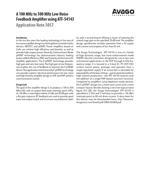
A 100 MHz to 500 MHz Low NoiseF eedback Amplifier using ATF-54143 Application Note 5057IntroductionIn the last few years the leading technology in the area of low noise amplifier design has been gallium arsenide (GaAs) devices, MESFET, and pHEMT. Power a mplifiers based on GaAs can achieve high efficiency and l inearity, as well as provide high output power. Recently, E nhancement Mode pHEMT technology has demonstrated i ndustry leading power added efficiency (PAE) and linearity performance for amplifier applications. The E-pHEMT technology provides high gain and very low noise. The high gain at low frequen-cies enables the use of feedback to linearize the E-pHEMT device. T his a pplication n ote s hows w hy E-pHEMT t echnology can provide superior electrical performance for low noise and high linearity amplifier design in UHF and VHF wireless communications bands.Design GoalsThe goal of the amplifier design is to produce a 100 to 500 MHz LNA, with an output third order intercept point (OIP3) of +36 dBm, a noise figure below 2.0 dB, and 20 dB gain with a flat gain response. RC feedback was used to provide good input and output match and to ensure unconditional stabil-ity, with a second feature offering a means of reducing the overall stage gain to the specified 20 dB level. The amplifier design specification includes operation from a 5V supply with current consumption of less than 65 mA.The Avago Technologies’ ATF-54143 is one of a family of high dynamic range, low noise enhancement mode PHEMT discrete transistors designed for use in low cost commercial applications in the VHF through 6 GHz fre-quency range. It is housed in a 4-lead SC-70 (SOT-343) surface mount plastic package, and operates from a single regulated supply. If an active bias is desirable for r epeatability of the bias setting—particularly desirable in h igh-volume production—the ATF-54143 requires only the a ddition of a single PNP bipolar junction transistor. Compared to amplifiers using depletion mode devices, the E-pHEMT design has a lower part count and a more compact layout. Besides having a very low typical noise figure (0.5 dB), the Avago Technologies’ ATF-54143 is specified at 2 GHz and 3-volt bias to provide a +36 dBm intercept point at 60 mA drain current. A data sheet for this d evice may be downloaded from: http://literature. /litweb/pdf/5989-0034EN.pdfLow Noise E-pHEMT Amplifier DesignUsing Avago Technologies’ EEsof Advanced Design System software, the amplifier circuit can be simulated in both linear and non-linear modes of operation. For the linear analysis the transistors can be modeled with a two-port s-parameter fi le u sing T ouchstone f ormat. M ore i nformation about Avago Technologies’ EDA software may be found at: /eesof-eda. T he appropriate ATF54143.s2p file can be downloaded from the Avago Technologies’ Wireless Design Center web site: http://www. (type A TF-54143 i n t he Quick Search at the top of the page. Under Search Results, click on the u nderlined A TF-54143. S croll d own t o t he S-parameters listing for 60 mA).For the non-linear analysis, a h armonic–balance (HB) simulation was used. HB is preferred over other non-linear methods b ecause it is computationally fast, handles both distributed and lumped element circuitry, and can easily include h igher-order h armonics a nd i ntermodulation p rod-ucts. H B w as u sed f or t he s imulation o f t he 1d B c ompression point (P-1dB) and output third order intercept point (OIP3). Although this non-linear transistor model closely predicts the DC and small signal behavior (including noise), it does not correctly predict the intercept point. To properly model the e xceptionally high linearity of the E-pHEMT transistor, a better model is required.Figure 1. ATF-54143 100-500 MHz HLA Active Bias Circuit Schematic.Besides providing information regarding gain, P -1dB , noise figure, and input and output return loss, the simulation provides very important information r egarding circuit stability. Unless a circuit is actually oscillating on the bench, it may be difficult to predict instabilities without actually presenting various VSWR loads at various phase angles to the amplifier. Calculating the Rollett stability factor (K) and generating stability circles are two methods made considerably easier with computer simulations. Simulated and measured results show the stability factor, K>1 (see Figure 2), at the cost of reduced third-order intercept point and output power, through the use of a series resistor on the output.Figure 3. Suggested RF layout to minimize inductance in feedback network.Figure 2. Simulated and measured stability factor K.FREQUENCY (GHz)R O L L E T T S T A B I L I T Y F A C T O R (K )20460.00To meet the goals for noise figure, intercept point, and gain, the drain source current (I ds ) was chosen to be 60 mA. The characterization data in the device data sheet shows that 60 mA gives the best IP 3, combined with a very low mini-mum noise figure (F min ). Also, as shown in the data sheet, a 3 V drain-to-source voltage (V ds ) gives a slightly higher gain and easily allows the use of a regulated 5 V supply. The use of a controlled amount of source inductance, usu-ally only a few tenths of a nanoHenry, can often be used to enhance LNA performance. This is effectively equivalent to i ncreasing the source leads by approximately .025 inch. The effect can be easily modeled using an RF simulation tool such as ADS. The usual side effect of excessive source inductance is gain peaking at a high frequency and resul-tant oscillations.Active BiasThe main advantage of an active biasing scheme is the ability to hold the drain to source current constant over a wide range of temperature variations. A very inexpensive method of accomplishing this is to use two PNP bipolar transistors arranged in a current mirror configuration as shown in Figure 1. Due to resistors R1 and R3, this circuit is not a true current mirror. However, if the voltage drops across R1 and R3 are kept identical, the current through R3 is stabilized and therefore I ds and V ds are also kept stable.A passive bias network is discussed in Application Note 1222: /litweb/pdf/5988-2336EN.pdfTransistor Q1 is configured with its base and collector tied t ogether. This acts as a simple PN junction, which helps to t emperature compensate the emitter-base junction of Q2. To calculate the values of R1, R2, R3, and R4, the following parameters must be known or chosen:I ds is the device drain-to-source current, 60 mA.I R is the reference current for active bias, 2.1 mA.V dd is the power supply voltage, 5V.V ds is the device drain-to-source voltage, 3.0V.V ds' is used in the equations due to the voltage drop across R7 and R8, 3.56V.V gs is the typical gate bias, 0.59V.V be1 is the typical base-emitter turn-on voltage for Q1 & Q2, 0.65V.Therefore, resistor R3, which sets the desired device drain current, is calculated as follows:(1) R3 ≈V dd – V ds'I ds + I c2where I C2 is chosen for stability to be 2.1 mA. This value is also equal to the reference current I R.The next three equations are used to calculate the rest of the biasing resistors for Figure 1.(2) R1 ≈V dd – V ds'I R Note that the voltage drop across R1 must be set equal to the voltage drop across R3, but with a current of I R.(3) R2 ≈V ds' – V belI RR2 sets the bias current through Q1.(4) R4 ≈VgI c2R4 sets the gate voltage. Ic2 = I e2, assuming the h fe of the PNP-transistors is high. Calculated resistor values differ from actual resistors due to available component values.Table 1. Component Parts List.C1=150 pF 0603 Chip CapacitorC2, C5=68 pF 0603 Chip CapacitorC3, C6=10 nF 0603 Chip CapacitorC4=100 pF 0603 Chip CapacitorC7=1 µF 0603 Chip CapacitorC8=180 pF 0402 Chip CapacitorC9=2.2 pF 0402 Chip CapacitorL1=150 nH TOKO LL1608-FSR15L2=120 nH TOKO LL1608-FSR12R1=680Ω 0603 Chip ResistorR2=1300Ω 0603 Chip ResistorR3=22Ω 0603 Chip ResistorR4=270Ω 0603 Chip ResistorR5=47Ω 0603 Chip ResistorR6=680Ω 0402 Chip ResistorR7, R8=4.7Ω 0603 Chip ResistorQ1, Q2 Phillips Semiconductor BCV62CQ3 Avago Technologies’ ATF-54143Input a nd o utput R F c onnectors a re E F J ohnson e nd-launch SMA connectors (p.n. 142-0701-881).The numbers associated with the chip capacitors and re-sistors refer to the dimensions of the components: 0402 = 40 x 20 mil, etc.Thus, by forcing the emitter voltage (V E ) of transistor Q1 equal to V ds , this circuit regulates the drain current in a manner similar to a current mirror. As long as Q2 oper-ates in the forward active mode, this holds true. In other words, the collector-base junction of Q2 must be keptr everse biased. An evaluation board was designed for the feedback ampli-fier network. T his single-layer board (see Figures 4 and 5) is 0.031-inch t hickness F R-4 m aterial w ith a d ielectric c onstant of 4.2. The feedback network should be made as short as possible, since introducing inductance into the feedback network causes instability in the 5-6 GHz region. The RC feedback uses 40 x 20 mil components that are soldered close together with a small solder pad in between.Figure 4. RF Layout for Demo Board.Figure 5. Assembly Drawing for Amplifier.The A TF-54143 i s c onditionally stable below 3.5 GHz, having 29-26 dB gain in the 100-500 MHz region. T he RC feedback reduces low frequency gain and increases the stability factor to >1 below 2 GHz. The amplifier uses a high-pass impedance matching network, consisting of C1 and L1, for the noise match. T he circuit loss will directly relate to noise figure, thus the Q of L1 is e xtremely important. The Toko LL1608-FSR15 is a small multi-layer chip inductor with a rated Q of 19 at 50 MHz. The shunt inductor (L1) provides low frequency gain reduction, which can minimize the amplifier’s susceptibility to overload from nearby low frequency transmitters. It is also part of the input match-ing network along with C1. C1 also doubles as a DC block, while L1 also provides a means of inserting gate voltage for the PHEMT. This requires a good bypass c apacitor in the form of C2.This network represents a compromise between noise figure, input return loss, and gain. Capacitors C2 and C5 provide in-band stability, while resistors R5 and R7 provide low-frequency stability by providing a resistive termina-tion. The high-pass network on the output consists of a series capacitor C4 and shunt inductors L2, with L2 also providing a means of inserting drain voltage for biasing up the PHEMT. V ery short transmission lines between each source lead and ground have been used. The RC feedback has a dramatic effect on in-band and out-of-band gain, stability, and input and output return loss.Figure 6. Simulation Results for Gain and Noise Figure.Figure 7. Simulation Results for Input and Output Return Loss.Simulated vs. Actual Performance of the E-pHEMT Broadband LNA Results from the simulation of gain, NF, and for input and output r eturn l oss a re s hown i n F igures 6 a nd 7, r espectively. Measured g ain a nd n oise fi gure a nd i nput a nd o utput r eturn loss appear in Figures 8 and 9, respectively. A summary of the measured results is shown in Table 2.Table 2. Measured Results.Frequency Gain NF P1dB OIP3 (MHz) (dB) (dB) (dBm) (dBm)100 20.8 1.20 +16.6 +34.5200 21.1 0.67 +16.6 +36.3300 21.4 0.62 +16.6 +36.5400 21.2 0.61 +16.6 +36.150020.50.70+16.8+36.5Figure 8. Measured Results for Gain and Noise Figure.Figure 9. Measured Results for Input and Output Return Loss.References[1] Ward, A. J. “Applications Note AN-1222: A Low NoiseHigh Intercept Point Amplifier for 1930 to 1990 MHzusing the ATF-54143 PHEMT.”[2] Maas, S tephan. N onlinear M icrowave C ircuits. I EEE P ress,New York, 1997.[3] Curtice, W. R. “A MESFET model for use in the design ofGaAs integrated circuits.”IEEE Trans Microwave TheoryTech. May 1980, Vol. MTT-28, pp. 448-456.Avago Eesof Advanced Design System (ADS) electronicdesign automation (EDA) software for system, RF, and DSPdesigners who develop communications products. Moreinformation about Avago T echnologies’ EDA software maybe found on /eesof-eda.Performance data for Avago Technologies’ ATF-54143 maybe found on /view/rfFor product information and a complete list of distributors, please go to our web site: Avago, Avago Technologies, and the A logo are trademarks of Avago Technologies, Limited in the United States and other countries. Data subject to change. Copyright © 2006-2010 Avago Technologies, Limited. All rights reserved.5989-0852EN May 12, 2010。
2.45GHz单级低噪声放大器的设计

2.45GHz单级低噪声放大器的设计汪海鹏;杨曙辉;陈迎潮;冯梦璐【摘要】设计了一种基于高电子迁移率晶体管ATF54143的单级低噪声放大器,采用ADS软件进行了设计优化.仿真结果表明在2.45 GHz处噪声系数小于1.5 dB,增益大于16.4 dB,稳定系数大于1.1,输入与输出的电压驻波比都小于1.1.在仿真基础上进行了实物加工,实测结果在2.45 GHz处|S21|为8.3 dB,|S11|和|S22 |最小值分别为-13.5 dB,-17.2 dB,1 dB压缩点的输出功率约为10 dBm.该放大器可应用于S波段的无线局域网,射频识别和北斗导航系统等领域.【期刊名称】《科学技术与工程》【年(卷),期】2015(015)023【总页数】4页(P160-163)【关键词】低噪声放大器;噪声系数;增益;稳定系数;电压驻波比【作者】汪海鹏;杨曙辉;陈迎潮;冯梦璐【作者单位】北京信息科技大学信息与通信工程学院,北京100101;北京信息科技大学信息与通信工程学院,北京100101;南卡罗莱纳大学电气工程系,美国哥伦比亚29208;北京信息科技大学信息与通信工程学院,北京100101;南卡罗莱纳大学电气工程系,美国哥伦比亚29208;北京信息科技大学信息与通信工程学院,北京100101【正文语种】中文【中图分类】TN722.3低噪声放大器的主要作用是放大从天线接收到的信号,用于后级电路处理,同时抑制噪声干扰,提高系统的灵敏度。
S波段的应用十分广泛,例如蓝牙系统、无线局域网IEEE 802.11b标准和北斗导航系统等[1—4]。
根据传输线原理,需在LNA设计中考虑分布参数,从而避免反射波对传输信号的影响。
此外,为了使放大器与前级天线和后级滤波器有良好的匹配,一般采用50 Ω的输入输出阻抗。
在实际设计中,还需要综合考虑低噪声放大器的增益、噪声系数与输入输出匹配[5,6]。
近年来学者们对S波段LNA进行了较多研究。
atf-54143低噪放芯片资料

Surface Mount Package SOT-343
Specifications
2 GHz; 3V, 60 mA (Typ.) 36.2 dBm output 3rd order intercept 20.4 dBm output power at 1 dB gain compression 0.5 dB noise figure 16.6 dB associated gain
Pin Connections and Package Marking
4Fx
DRAIN
SOURCE
Applications
GATE
SOURCE
Note: Top View. Package marking provides orientation and identification “4F” = Device Code “x” = Date code character identifies month of manufacture.
ቤተ መጻሕፍቲ ባይዱ
Parameter and Test Condition
Operational Gate Voltage Threshold Voltage Saturated Drain Current Transconductance Gate Leakage Current Noise Figure[1] Associated Gain[1] Output 3rd Order Intercept Point[1] 1dB Compressed Output Power[1] f = 2 GHz f = 900 MHz f = 2 GHz f = 900 MHz f = 2 GHz f = 900 MHz f = 2 GHz f = 900 MHz Vds = 3V, Ids = 60 mA Vds = 3V, Ids = 4 mA Vds = 3V, Vgs = 0V
基于ATF—55143的4.4GHz射频低噪声放大器设计与仿真

基于ATF—55143的4.4GHz射频低噪声放大器设计与仿真作者:任朝阳张凯岳晓惠金非凡曹智辉来源:《科学导报·学术》2020年第14期摘要:本文设计了带宽为400MHz,中心频率为4.4GHz射频低噪声放大器,选用安捷伦公司的高电子迁移率晶体管ATF-55143,利用安捷伦公司的微波仿真软件Advanced Design System(ADS)进行原理图和版图的设计、仿真及优化。
仿真设计结果表明:在工作频段范围内,其增益S21>9dB、噪声系数NF<2dB、输入反射系数S11<-15dB、输出反射系数S22<-15dB、功耗P<30mW;关键词:低噪声;ADS;放大器引言射频低噪声放大器在通信、遥测遥感、射电天文、雷达以及电子对抗等领域的射频接收机前端已成为必不可少的重要组成部分。
低噪声放大器在射频前段的主要作用为在放大信号的同时尽可能低的引入内部噪声,因此噪声系数是低噪声放大器的一个重要指标。
低噪声放大器的噪声系数关乎着射频前端及其整个通信系统的接收灵敏度。
由于电磁波的传输损耗、水汽吸收损耗随着电磁波的频率升高而增大,这就对于工作频段较高的低噪声放大器的噪声系数提出了较高的要求。
[1]本文采用稳定性设计和偏置电路设计相结合,以此提高电路设计效率。
首先,选择合适的晶体管,确立静态工作点;设计合理的输入输出匹配网络,采用稳定性设计和偏置电路设计综合考虑的方法,以满足增益、噪声系数以及输入输出驻波比等指标;最后进行微带线版图仿真、优化及设计。
1.放大器基本原理图1为晶体管放大器常规电路原理图。
其中,信号源反射系数; 晶体管输入端反射系数; 负载反射系数; 晶体管的输出反射系数。
根据微波网络基本理论可知,放大器的输入、输出匹配网络用来减少反射以提高传输功率流量,其放大器指标由其特定偏置条件下的S参数确定[2]。
和决定着放大器的电路的噪声参量、增益、稳定性以及电压驻波比等性能参数[3]。
接收机前端宽带低噪声放大器仿真设计

接收机前端宽带低噪声放大器仿真设计作者:王建峰来源:《硅谷》2013年第03期摘要设计了一个1G-1.7 GHz宽带低噪声放大器。
该放大器采用两级增强型场效应管(ATF54143)级联而成,每级都用独立电源供电。
应用射频电路仿真软件ADS对输入输出匹配电路进行设计并优化,最后通过原理图-版图联合仿真(Cosimulation with layout)得到放大器的各项指标。
在1G-1.7 GHz频带内,噪声系数(NF)小于0.5 dB,带内增益大于28 dB,带内增益平坦度±1 dB以内,S11和S22都小于-15 dB。
仿真结果表明,该设计完全满足性能指标要求。
关键词低噪声放大器;ADS仿真;噪声系数中图分类号:TN722 文献标识码:A 文章编号:1671—7597(2013)021-068-02在无线通信系统中,低噪声放大器是接收机前端的第一个单元电路,发挥着重要作用。
接收机接收信号的灵敏度主要由低噪声放大器(LNA)的噪声系数(NF)与功率增益决定。
LNA的噪声系数显著地影响着接收机的整体性能,另外,它的功率增益能明显抑制来自后级的噪声。
对整个系统的线性度而言,低噪声放大器的非线性必须尽可能的小。
1 LNA电路设计1.1 LNA的各项指标与设计思路LNA需要达到的指标:工作频带1G-1.7 GHz,噪声系数(NF)小于0.5 dB,带内增益大于28 dB,带内增益平坦度±1 dB以内,S11和S22都小于-15 dB。
考虑到增益和噪声系数要求较高,采用E-PHEMT晶体管(ATF54143),安捷伦公司提供了其精确的ADS模型,便于仿真,而且工作时不需要负的栅极电压,便于单电源供电。
1.2 偏置电路根据增强型场效应管ATF54143的Datasheet,在漏极电压为3 V,漏极电流为60 mA的偏置下,栅极电压为0.56 V,因而这里选用单极性的无源偏置网络,偏置电路如图1(a)所示。
低噪声放大器的设计与应用概要

低噪声放大器的设计与应用
放大器的应用在工业技术领域中得到了广泛的认可,在许多场合下需要将传感器得到的微弱电信号放大来驱动相应的执行机构。比如电子秤,压力传感器转化得到的电信号十分微弱,不足以驱动相应的显示功能和准确的被辨识,所以需要放大器将此微弱的电信号进行放大。
低噪声放大器原理结构图
隔 离 器
低 噪 声 管
放 大 管
放 大 管
隔 离 器
限 幅 组 件 ALC
放 大 管
检波组件
限幅运 算电路低噪声放大来自模块结构说明1、隔离器:主要用于高频信号的单向输入,对于反向的高频信号进行隔离,同时对各端口的驻波进行匹配。 2、低噪声管:ATF54143,利用管子的低噪声特性,减少模块的内部噪声,降低低噪声模块的噪声电平,使整机的接收灵敏度提高。 3、放大管:进一步放大高频信号 。 4、限幅组件:包含由PIN管组成压控的衰减电路(ALC)以及由HMC273组成的数控衰减电路(ATT)。 5、检波组件:由MAX-4003芯片构成的检波电路检测出模块的输出功率大小。 6、限幅运算电路:根据检波组件对高频信号检测出的直流电压进行运算,对限幅电路进行控制。
1989年,由混合微波集成电路技术制成的三阶InP基放大器在60-65GHz频段内,已达到噪声系数3.0dB,其相关增益为22dB。三年以后,使用0.1μm InP基HEMT制成的三阶放大器在60GHz下已达到1.6dB的噪声系数,其相关增益16dB。 进入90年代,随着晶体材料技术和微细加工技术的发展,毫米波MMIC进入实用化阶段。MMIC开始主要应用于军用系统,90年代以来,MMIC在商用产品中开拓了广阔的市场。这主要是商用无线通信市场,如低轨道卫星移动通信、环球定位卫星系统等。
方案设计
- 1、下载文档前请自行甄别文档内容的完整性,平台不提供额外的编辑、内容补充、找答案等附加服务。
- 2、"仅部分预览"的文档,不可在线预览部分如存在完整性等问题,可反馈申请退款(可完整预览的文档不适用该条件!)。
- 3、如文档侵犯您的权益,请联系客服反馈,我们会尽快为您处理(人工客服工作时间:9:00-18:30)。
A 100 MHz to 500 MHz Low NoiseF eedback Amplifier using ATF-54143 Application Note 5057IntroductionIn the last few years the leading technology in the area of low noise amplifier design has been gallium arsenide (GaAs) devices, MESFET, and pHEMT. Power a mplifiers based on GaAs can achieve high efficiency and l inearity, as well as provide high output power. Recently, E nhancement Mode pHEMT technology has demonstrated i ndustry leading power added efficiency (PAE) and linearity performance for amplifier applications. The E-pHEMT technology provides high gain and very low noise. The high gain at low frequen-cies enables the use of feedback to linearize the E-pHEMT device. T his a pplication n ote s hows w hy E-pHEMT t echnology can provide superior electrical performance for low noise and high linearity amplifier design in UHF and VHF wireless communications bands.Design GoalsThe goal of the amplifier design is to produce a 100 to 500 MHz LNA, with an output third order intercept point (OIP3) of +36 dBm, a noise figure below 2.0 dB, and 20 dB gain with a flat gain response. RC feedback was used to provide good input and output match and to ensure unconditional stabil-ity, with a second feature offering a means of reducing the overall stage gain to the specified 20 dB level. The amplifier design specification includes operation from a 5V supply with current consumption of less than 65 mA.The Avago Technologies’ ATF-54143 is one of a family of high dynamic range, low noise enhancement mode PHEMT discrete transistors designed for use in low cost commercial applications in the VHF through 6 GHz fre-quency range. It is housed in a 4-lead SC-70 (SOT-343) surface mount plastic package, and operates from a single regulated supply. If an active bias is desirable for r epeatability of the bias setting—particularly desirable in h igh-volume production—the ATF-54143 requires only the a ddition of a single PNP bipolar junction transistor. Compared to amplifiers using depletion mode devices, the E-pHEMT design has a lower part count and a more compact layout. Besides having a very low typical noise figure (0.5 dB), the Avago Technologies’ ATF-54143 is specified at 2 GHz and 3-volt bias to provide a +36 dBm intercept point at 60 mA drain current. A data sheet for this d evice may be downloaded from: http://literature. /litweb/pdf/5989-0034EN.pdfLow Noise E-pHEMT Amplifier DesignUsing Avago Technologies’ EEsof Advanced Design System software, the amplifier circuit can be simulated in both linear and non-linear modes of operation. For the linear analysis the transistors can be modeled with a two-port s-parameter fi le u sing T ouchstone f ormat. M ore i nformation about Avago Technologies’ EDA software may be found at: /eesof-eda. T he appropriate ATF54143.s2p file can be downloaded from the Avago Technologies’ Wireless Design Center web site: http://www. (type A TF-54143 i n t he Quick Search at the top of the page. Under Search Results, click on the u nderlined A TF-54143. S croll d own t o t he S-parameters listing for 60 mA).For the non-linear analysis, a h armonic–balance (HB) simulation was used. HB is preferred over other non-linear methods b ecause it is computationally fast, handles both distributed and lumped element circuitry, and can easily include h igher-order h armonics a nd i ntermodulation p rod-ucts. H B w as u sed f or t he s imulation o f t he 1d B c ompression point (P-1dB) and output third order intercept point (OIP3). Although this non-linear transistor model closely predicts the DC and small signal behavior (including noise), it does not correctly predict the intercept point. To properly model the e xceptionally high linearity of the E-pHEMT transistor, a better model is required.Figure 1. ATF-54143 100-500 MHz HLA Active Bias Circuit Schematic.Besides providing information regarding gain, P -1dB , noise figure, and input and output return loss, the simulation provides very important information r egarding circuit stability. Unless a circuit is actually oscillating on the bench, it may be difficult to predict instabilities without actually presenting various VSWR loads at various phase angles to the amplifier. Calculating the Rollett stability factor (K) and generating stability circles are two methods made considerably easier with computer simulations. Simulated and measured results show the stability factor, K>1 (see Figure 2), at the cost of reduced third-order intercept point and output power, through the use of a series resistor on the output.Figure 3. Suggested RF layout to minimize inductance in feedback network.Figure 2. Simulated and measured stability factor K.FREQUENCY (GHz)R O L L E T T S T A B I L I T Y F A C T O R (K )20460.00To meet the goals for noise figure, intercept point, and gain, the drain source current (I ds ) was chosen to be 60 mA. The characterization data in the device data sheet shows that 60 mA gives the best IP 3, combined with a very low mini-mum noise figure (F min ). Also, as shown in the data sheet, a 3 V drain-to-source voltage (V ds ) gives a slightly higher gain and easily allows the use of a regulated 5 V supply. The use of a controlled amount of source inductance, usu-ally only a few tenths of a nanoHenry, can often be used to enhance LNA performance. This is effectively equivalent to i ncreasing the source leads by approximately .025 inch. The effect can be easily modeled using an RF simulation tool such as ADS. The usual side effect of excessive source inductance is gain peaking at a high frequency and resul-tant oscillations.Active BiasThe main advantage of an active biasing scheme is the ability to hold the drain to source current constant over a wide range of temperature variations. A very inexpensive method of accomplishing this is to use two PNP bipolar transistors arranged in a current mirror configuration as shown in Figure 1. Due to resistors R1 and R3, this circuit is not a true current mirror. However, if the voltage drops across R1 and R3 are kept identical, the current through R3 is stabilized and therefore I ds and V ds are also kept stable.A passive bias network is discussed in Application Note 1222: /litweb/pdf/5988-2336EN.pdfTransistor Q1 is configured with its base and collector tied t ogether. This acts as a simple PN junction, which helps to t emperature compensate the emitter-base junction of Q2. To calculate the values of R1, R2, R3, and R4, the following parameters must be known or chosen:I ds is the device drain-to-source current, 60 mA.I R is the reference current for active bias, 2.1 mA.V dd is the power supply voltage, 5V.V ds is the device drain-to-source voltage, 3.0V.V ds' is used in the equations due to the voltage drop across R7 and R8, 3.56V.V gs is the typical gate bias, 0.59V.V be1 is the typical base-emitter turn-on voltage for Q1 & Q2, 0.65V.Therefore, resistor R3, which sets the desired device drain current, is calculated as follows:(1) R3 ≈V dd – V ds'I ds + I c2where I C2 is chosen for stability to be 2.1 mA. This value is also equal to the reference current I R.The next three equations are used to calculate the rest of the biasing resistors for Figure 1.(2) R1 ≈V dd – V ds'I R Note that the voltage drop across R1 must be set equal to the voltage drop across R3, but with a current of I R.(3) R2 ≈V ds' – V belI RR2 sets the bias current through Q1.(4) R4 ≈VgI c2R4 sets the gate voltage. Ic2 = I e2, assuming the h fe of the PNP-transistors is high. Calculated resistor values differ from actual resistors due to available component values.Table 1. Component Parts List.C1=150 pF 0603 Chip CapacitorC2, C5=68 pF 0603 Chip CapacitorC3, C6=10 nF 0603 Chip CapacitorC4=100 pF 0603 Chip CapacitorC7=1 µF 0603 Chip CapacitorC8=180 pF 0402 Chip CapacitorC9=2.2 pF 0402 Chip CapacitorL1=150 nH TOKO LL1608-FSR15L2=120 nH TOKO LL1608-FSR12R1=680Ω 0603 Chip ResistorR2=1300Ω 0603 Chip ResistorR3=22Ω 0603 Chip ResistorR4=270Ω 0603 Chip ResistorR5=47Ω 0603 Chip ResistorR6=680Ω 0402 Chip ResistorR7, R8=4.7Ω 0603 Chip ResistorQ1, Q2 Phillips Semiconductor BCV62CQ3 Avago Technologies’ ATF-54143Input a nd o utput R F c onnectors a re E F J ohnson e nd-launch SMA connectors (p.n. 142-0701-881).The numbers associated with the chip capacitors and re-sistors refer to the dimensions of the components: 0402 = 40 x 20 mil, etc.Thus, by forcing the emitter voltage (V E ) of transistor Q1 equal to V ds , this circuit regulates the drain current in a manner similar to a current mirror. As long as Q2 oper-ates in the forward active mode, this holds true. In other words, the collector-base junction of Q2 must be keptr everse biased. An evaluation board was designed for the feedback ampli-fier network. T his single-layer board (see Figures 4 and 5) is 0.031-inch t hickness F R-4 m aterial w ith a d ielectric c onstant of 4.2. The feedback network should be made as short as possible, since introducing inductance into the feedback network causes instability in the 5-6 GHz region. The RC feedback uses 40 x 20 mil components that are soldered close together with a small solder pad in between.Figure 4. RF Layout for Demo Board.Figure 5. Assembly Drawing for Amplifier.The A TF-54143 i s c onditionally stable below 3.5 GHz, having 29-26 dB gain in the 100-500 MHz region. T he RC feedback reduces low frequency gain and increases the stability factor to >1 below 2 GHz. The amplifier uses a high-pass impedance matching network, consisting of C1 and L1, for the noise match. T he circuit loss will directly relate to noise figure, thus the Q of L1 is e xtremely important. The Toko LL1608-FSR15 is a small multi-layer chip inductor with a rated Q of 19 at 50 MHz. The shunt inductor (L1) provides low frequency gain reduction, which can minimize the amplifier’s susceptibility to overload from nearby low frequency transmitters. It is also part of the input match-ing network along with C1. C1 also doubles as a DC block, while L1 also provides a means of inserting gate voltage for the PHEMT. This requires a good bypass c apacitor in the form of C2.This network represents a compromise between noise figure, input return loss, and gain. Capacitors C2 and C5 provide in-band stability, while resistors R5 and R7 provide low-frequency stability by providing a resistive termina-tion. The high-pass network on the output consists of a series capacitor C4 and shunt inductors L2, with L2 also providing a means of inserting drain voltage for biasing up the PHEMT. V ery short transmission lines between each source lead and ground have been used. The RC feedback has a dramatic effect on in-band and out-of-band gain, stability, and input and output return loss.Figure 6. Simulation Results for Gain and Noise Figure.Figure 7. Simulation Results for Input and Output Return Loss.Simulated vs. Actual Performance of the E-pHEMT Broadband LNA Results from the simulation of gain, NF, and for input and output r eturn l oss a re s hown i n F igures 6 a nd 7, r espectively. Measured g ain a nd n oise fi gure a nd i nput a nd o utput r eturn loss appear in Figures 8 and 9, respectively. A summary of the measured results is shown in Table 2.Table 2. Measured Results.Frequency Gain NF P1dB OIP3 (MHz) (dB) (dB) (dBm) (dBm)100 20.8 1.20 +16.6 +34.5200 21.1 0.67 +16.6 +36.3300 21.4 0.62 +16.6 +36.5400 21.2 0.61 +16.6 +36.150020.50.70+16.8+36.5Figure 8. Measured Results for Gain and Noise Figure.Figure 9. Measured Results for Input and Output Return Loss.References[1] Ward, A. J. “Applications Note AN-1222: A Low NoiseHigh Intercept Point Amplifier for 1930 to 1990 MHzusing the ATF-54143 PHEMT.”[2] Maas, S tephan. N onlinear M icrowave C ircuits. I EEE P ress,New York, 1997.[3] Curtice, W. R. “A MESFET model for use in the design ofGaAs integrated circuits.”IEEE Trans Microwave TheoryTech. May 1980, Vol. MTT-28, pp. 448-456.Avago Eesof Advanced Design System (ADS) electronicdesign automation (EDA) software for system, RF, and DSPdesigners who develop communications products. Moreinformation about Avago T echnologies’ EDA software maybe found on /eesof-eda.Performance data for Avago Technologies’ ATF-54143 maybe found on /view/rfFor product information and a complete list of distributors, please go to our web site: Avago, Avago Technologies, and the A logo are trademarks of Avago Technologies, Limited in the United States and other countries. Data subject to change. Copyright © 2006-2010 Avago Technologies, Limited. All rights reserved.5989-0852EN May 12, 2010。