太阳能跟踪器
太阳能跟踪器小知识
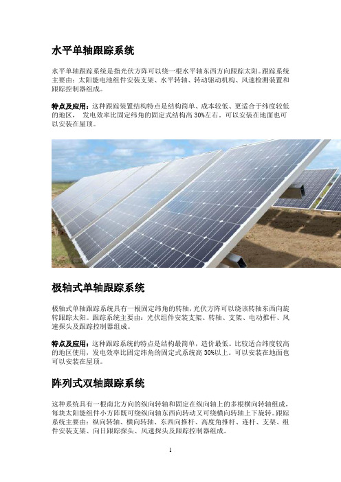
水平单轴跟踪系统水平单轴跟踪系统是指光伏方阵可以绕一根水平轴东西方向跟踪太阳。
跟踪系统主要由:太阳能电池组件安装支架、水平转轴、转动驱动机构、风速检测装置和跟踪控制器组成。
特点及应用:这种跟踪装置结构特点是结构简单、成本较低、更适合于纬度较低的地区,发电效率比固定纬角的固定式结构高30%左右。
可以安装在地面也可以安装在屋顶。
极轴式单轴跟踪系统极轴式单轴跟踪系统具有一根固定纬角的转轴,光伏方阵可以绕该转轴东西向旋转跟踪太阳。
跟踪系统主要由:光伏组件安装支架、转轴、支架、电动推杆、风速探头及跟踪控制器组成。
特点及应用:这种跟踪系统的特点是结构最简单,造价最低。
比较适合纬度较高的地区使用,发电效率比固定纬角的固定式系统高30%以上。
可以安装在地面也可以安装在屋顶。
阵列式双轴跟踪系统这种系统具有一根南北方向的纵向转轴和固定在纵向轴上的多根横向转轴组成,每块太阳能组件小方阵既可绕纵向轴东西向转动又可绕横向转轴上下旋转。
跟踪系统主要由:纵向转轴、横向转轴、东西向推杆、高度角推杆、连杆、支架、组件安装支架、向日跟踪探头、风速探头及跟踪控制器组成。
特点及应用:与水平单轴跟踪相比,实现了双轴跟踪,发电效率更高,比固定纬角的固定结构高45%以上,与立柱式跟踪相比,系统的高度更低,抗风性能更好,单位面积的安装功率更高。
既可安装在地面也可安装在屋顶。
立柱式双轴跟踪系统有一根立轴和一根水平轴,整个光伏方阵由一根立柱支撑,光伏方阵既可绕立轴跟踪太阳的方位角,同时绕水平轴跟踪太阳的高度角,它完全无限制地跟踪太阳方位,最大限度地发挥跟踪系统的效能。
跟踪系统主要由:组件安装支架、水平轴、水平动力头、电动推杆、立柱、向日跟踪探头、风速探头、跟踪控制器等组成。
特点及应用:跟踪范围最大、跟踪效率最高,比固定纬角的固定结构高50%以上。
一般仅适合安装在地面。
太阳能跟踪器 Solar Tracker 外文翻译
Solar TrackerDavid Crowe, Jeff McCormick, Joel Mitchell,Thomas Stratton, Jeff SchwaneDecember 15, 2005Duke University Smart House Pratt School of EngineeringAbstractThe Solar Tracker team was formed in the fall of 2005 from five students in an ME design team, and a Smart House liaison. We continued the work of a previous solar tracker group. The task was to design a prototype tracking device to align solar panels optimally to the sun as it moves over the course of the day. The implementation of such a system dramatically increases the efficiency of solar panels used to power the Smart House. This report examines the process of designing and constructing the prototype, the experiences and problems encountered, and suggestions for continuing the project.1.IntroductionSolar tracking is the process of varying the angle of solar panels and collectors to take advantage of the full amount of the sun‟s energy. This is done by rotating panels to be perpendicular to the sun‟s angle of incidence. Initi al tests in industry suggest that this process can increase the efficiency of a solar power system by up to 50%. Given those gains, it is an attractive way to enhance an existing solar power system. The goal is to build a rig that will accomplish the solar tracking and realize the maximum increase in efficiency. The ultimate goal is that the project will be cost effective – that is, the gains received by increased efficiency will more than offset the one time cost of developing the rig over time. In addition to the functional goals, the Smart House set forth the other following goals for our project: it must not draw external power (self-sustaining), it must be aesthetically pleasing, and it must be weatherproof.The design of our solar tracker consists of three components: the frame, the sensor, and the drive system. Each was carefully reviewed and tested, instituting changes and improvements along the design process. The frame for the tracker is an aluminumprismatic frame supplied by the previous sol ar tracking group. It utilizes an …A-frame‟ design with the rotating axle in the middle. Attached to the bottom of this square channel axle is the platform which will house the main solar collecting panels. The frame itself is at an angle to direct the panels toward the sun (along with the inclination of the roof). Its rotation tracks the sun from east to west during the day.The sensor design for the system uses two small solar panels that lie on the same plane as the collecting panels. These sensor panels have mirrors vertically attached between them so that, unless the mirror faces do not receive any sun, they are shading one of the panels, while the other is receiving full sunlight. Our sensor relies on this difference in light, which results in a large impedance difference across the panels, to drive the motor in the proper direction until again, the mirrors are not seeing any sunlight, at which point both solar panels on the sensor receive equal sunlight and no power difference is seen.After evaluation of the previous direct drive system for the tracker, we designed a belt system that would be easier to maintain in the case of a failure. On one end of the frame is a motor that has the drive pulley attached to its output shaft. The motor rotates the drive belt which then rotates the pulley on the axle. This system is simple and easily disassembled. It is easy tointerchange motors as needed for further testing and also allows for optimization of the final gear ratio for response of the tracker.As with any design process there were several setbacks to our progress. The first and foremost was inclement weather which denied us of valuable testing time. Despite the setbacks, we believe this design and prototype to be a very valuable proof-of-principle. During our testing we have eliminated many of the repetitive problems with the motor and wiring so that future work on the project will go more smoothly. We also have achieved our goal of tracking the sun in a …hands-off‟ demo. We were able to have the tracker rotate under its own power to the angle of the sun and stop without any assistance. This was the main goal set forth to us by the Smart House so we believe our sensed motionprototype for solar tracking will be the foundation as they move forward in the future development and implementation of this technology to the house.2. Defining the ProblemThe project was to complete the “REV 2” design phase of the solar tracker to be used on the Smart House. While the team was comprised of members from the ME160 senior design course, the customer for this project was to be the Smart House organization. Jeff Schwane, a representative from the Smart House, was our liaison and communicated to our group the direction Smart House leadership wished us to proceed.At our first meeting with Jeff and Tom Rose, the following needs were identified:1.Track the sun during the daye no external power source3.Weather proof4.Cost effective power gain5.Must look good6.Solar panel versatile i.e. can fit different types of panelsWith these needs in hand, we constructed a Quality Function Deployment chart. This chart can be found in Appendix A. The QFD showed the major areas of concern might have been: number of panels/size of panels, internal power requirements, motor torque required.At our first meeting we were also able to set up our goals for the semester. Having a working prototype capable of tracking the sun was to be the main goal for the end of the semester, but we soon found that in order to accomplish this, we would be forced to omit portions of the design criteria in hopes they would be worked out later. This would result in the optimization of platform space on the roof to be irrelevant, with our goal being to have one platform track. It also led to the assumption that our base would not need to be tested for stability or required to be fastened to the roof. With an idea of where we were to begin, from scratch with the possibility of using the frame from the “REV 1” design, and an idea of where we were to finish, with a moving prototype, we constructed the Ganttchart that can be found in Appendix B. Our group planned to meet with Jeff once a week to make sure we were on track with the needs of the Smart House. Jeff would also meet with Tom Rose, the director of Smart House, at least once a week in order to keep everyone on the same page. With our goals in mind we embarked on the process of idea generation.3. Concepts and Research3.1 Tracking TypeOur group used a brainstorming approach to concept generation. We thought of ideas for different solar tracking devices, which proved difficult at times due to the existing frame and concept presented to us by Smart House. Other concepts were generated through research of pre-existing solar tracking devices. Originally our concept generation was geared towards creating a completely new solar tracker outside of the constraints of the previous structure given to us by Smart House. This initial brainstorming generated many concepts. The first one was a uni-axial tracking system that would track the sun east to west across the sky during the course of a day and return at the end of the day. This concept presented the advantage of simplicity and presented us with the option to use materials from the previous structure (which was also intended to be a uni-axial tracker) in construction. Another more complex concept was to track the sun bi-axially which would involve tracking the sun both east to west and throughout the seasons. The advantage of this concept was a more efficient harvesting of solar energy. The third concept was to only track throughout the seasons. This would provide small efficiency gains but nowhere near the gain provided by tracking east to west.The different structures we came up with to accomplish tracking motion included a rotating center axle with attached panels, hydraulic or motorized lifts which would move the main panel in the direction of the sun, and a robotic arm which would turn to face the sun. The clear efficiency gains coupled with the simplicity of design of the uni-axial tracking system and the existence of usable parts (i.e. motor and axle) for the rotating center axle structure, led us to the choice of the East to West tracking, rotating center axleconcept.3.2 StructureOnce the method of motion was chosen, it was necessary to generate concepts for the structural support of the axle. Support could be provided by the triangular prismatic structure which was attempted by the previous Smart House solar tracker group or through the use of columns which would support the axis on either side. While the prismatic structure presented the advantage of mobility and an existing frame, the columns would have provided us with ease of construction, simple geometric considerations, and ease of prospective mounting on the roof. Due to the heightened intensity of time considerations, the previous financial commitment to the prismatic structure by Smart House, and our limited budget, the presence of the pre-existing frame proved to be the most important factor in deciding on a structure. Due to these factors we decided to work within the frame which was provided to us from the previous Solar Tracker group.3.2 Tracking MotionOnce the structural support was finalized we needed to decide on a means to actualize this motion. We decided between sensed motion, which would sense the sun‟s position and move to follow it, and continuous clock type motion, which would track the sun based on its pre-determined position in the sky. We chose the concept of continuous motion based on its perceived accuracy and the existence of known timing technology. During the evaluation stage, however, we realized that continuous motion would prove difficult. One reason was the inability to draw constant voltage and current from the solar panels necessary to sustain consistent motion, resulting in the necessity for sensing the rotation position to compensate. Continuous motion also required nearly constant power throughout the day, which would require a mechanism to store power. Aside from these considerations, the implementation of a timing circuit and location sensing device seemed daunting. After consulting Dr. Rhett George, we decided on a device using two panels and shading for sensed motion.4. Analysis and Embodiment4.1 Structure GeometryThe geometry of the frame was created in order to allow the solar panels to absorb light efficiently. This was done by allowing rotation in the east-west direction for tracking the sun daily and a 36° inclination (Durham‟s latitu de) towards the south. Because this frame was designed to be placed on a roof with a slope of 25°, the actual incline of the frame was made to be 11°.The geometry of the existing platform structure was modified. This was done in order to incorporate the results from the Clear Day Model supplied to us by Dr. Knight. This model led to the conclusion that the platform should track to up to 60° in both directions of horizontal. Thus, the angle range of the frame had to be increased. The sides of the frame were brought in to increase the allowable angle of rotation, and they were brought in proportionally to maintain the inclination angle of 11°. Also, crosspieces were moved to the inside of the frame to allow greater rotation of the platform before it came into contact with the support structure.The panels used for sensing and powering rotation were placed on the plane of the platform. Mirrors were placed perpendicular to and in between the panels to shade one and amplify the other in order to produce a difference to power the motor. The sensing panels were placed outside the platform area to maintain the largest area possible for collecting panels. A third sensing panel was mounted nearly vertical and facing east to aid rotation back towards the sun in the morning. This panel was attached to the frame under the platform, so that during most of the day, it‟s shaded with minimal effects on sensed rotation.Minimizing the torques on the motor was a main concern in order to minimize the motor power needed. The platform designed for the placement of the collecting solar panels was placed under the rotational shaft so that the panels would be aligned with it the rotational axis. Since the main panels comprise the majority of the weight putting these in the plane of the rotational axis reduces torque on the shaft. The sensing panels were placed symmetrically about the axis of rotation in order to prevent additional torque on themotor. The third panel was attached to the frame instead of the platform or rotational shaft so as to also avoid any torque.4.2 MaterialsMaterials selection for most of the frame was simple because it had already been constructed. The mirrors used for the amplification and shading of the sensing panels were also already purchased and available for use. Additional parts for attachment of the panels and mirrors to the frame were taken from the scrap pieces available in the machine shop. In our selection of sensing panels, size and power needed to be balanced effectively. The panels were to be as small as possible in order to add minimal stress and weight to the frame but also needed to be powerful enough to power the rotation of the platform. Therefore, the most powerful of the intermediate sized panels available were selected. The panels purchased also appeared to be the most reliable of our options.4.3 Drive MechanismAfter designing a prototype and testing it, the motor purchased and used by the previous solar tracker group was slipping. It was removed, and the installation of a gear system with another simple motor was suggested and attempted. Professor Knight supplied some gears as well as some belts and pulleys. One end of the shaft was lathed so that one of the pulleys could be set on it, and spacers were bought so that a 6V motor we had available could power another pulley. These pulleys were to be connected by a belt. This motor demonstrated insufficient strength to turn the rotational shaft. The original motor, once detached, was taken apart and examined. Itappeared to be working again so a new pulley was purchased to fit it and was attached in the place of the 6V motor.5. Detailed Design5.1 FrameThe frame was designed from one inch square aluminum tubing, and a five foot long, two inch square tube for the axle. It is constructed with a rigid base and triangular prismatic frame with side supporting bars that provide stability. The end of the axle is attached to a system of pulleys which are driven by the motor. It is easily transported byremoving the sides of the base and folding the structure.5.2 SensorOur sensing panels are bolted to the bottom of the main solar panel frame and braced underneath with half inch L-brackets. The mirrors are attached to the inside of the sensing panels and braced by L-brackets as well. The whole structure attaches easily to the main panel frame which is attached to the main axle using four 2-inch U-bolts. A third panel is bolted to the structure to return the main panels direction towards the horizon of sunrise.5.3 How the Sensor WorksOur sensor creates movement of the motor by shading one of the panels and amplifying the other when the system is not directly facing the sun. The two sensing panels are mounted parallel to the main panels symmetrically about the center axle with two mirrors in between them. The shading on one of the panels creates high impedance, while the amplified panel powers the motor. This happens until the panels receive the same amount of sunlight and balance each other out (i.e. when the sensing panels and main panels are facing the sun.). We initially attempted using a series configuration to take advantage of the voltage difference when one of the panels was shaded (Appendix C). This difference, however, was not large enough to drive the motor. We subsequently attempted a parallel configuration which would take advantage of the impedance of the shaded panel (Appendix C) and provide the current needed to drive the motor. Once the sensing mechanism has rotated from sunrise to sunset, the third panel, which is usually shaded, uses sunlight from the sunrise of the next day to power the motor to return the panels towards the direction of the sun.6. Prototype TestingInitial testing was done using just the sensing component and a 6V motor. The panels were tilted by hand to create shading and amplification. A series configuration of the sensing panels was initially tested and proved ineffective. Data acquisition showed a maximum of a 2V difference across the motor, which was insufficient to power it. Upon testing the panels individually, it was discovered that the open voltage across eachindividual panel would only vary between 21.5V and 19.5V when fully amplified and fully shaded, respectively. The current running through each panel, however, was seen to fluctuate between nearly 0 amps when shaded, up to 0.65 amps when fully amplified. Therefore, in order to take advantage of the increase in impedance of the solar panels due to shading, we chose to put our sensing panels in parallel with each other and the motor. Tests with this configuration turned the motor in one direction, stopped when the sensing panels were nearly perpendicular to the sun, and reversed direction as the panels rotated past perpendicular. We found the angle range necessary to stop the motor to be very small. It was also observed that the panels rotated to slightly past perpendicular when they ceased motion. This error may be due to a difference in the innate resistance in each individual sensing panel. When tested it was found that one panel had a resistance of 52 kΩ, and the other panel resistance was 53 kΩ. Other testing found the voltage and current provided by the sensing solar panels to the motor to be consistent at all points, excluding when the solar panels are directly facing the sun. Through testing it was concluded that resistance may need to be added to one of the panels to compensate for the differences in the internal resistances of the individual panels, and a voltage regulator needs to be added to decrease the voltage seen across the motor. The original motor was prone to failure as its slippage caused the breakdown of our initial prototype after testing. This led to the institution of the pulley and belt driven system which would allow for easier maintenance given motor failure or slippage. The success of our initial testing and prototype proved to us the efficacy of our solar tracker design.7. ConclusionThroughout this project we enlisted the support of multiple resources (i.e. ME and EE professors, previous Smart House teams). We learned early on that a clear problem definition was essential to efficient design and progress. We struggled initially as we tried to design a tracking device that was different from the previous solar tracker group‟s attempt, without fully weighing the size of their investment and the advantages of using the existing frame for our purposes. As we worked with the fixed frame construction from theprevious group we learned that variability of design is key, especially when in the initial phases of prototyping. After many setbacks in testing of the solar panels, we learned that when working with solar panels, much time needs to be set aside for testing due to the unpredictability of the weather.The actual implementation of using the prototype in its intended location on the Smart House roof requires weather-proofing to protect the wiring and electrical connections from the elements, housing for the motor, a bracing system to attach the structure to the roof, and possible redesign to eliminate excess height and simplify overall geometry. The efficiency of the sensor system could be improved by widening the mirrors or by placing blinders along the sides of the panels to decrease the effects of reflected and refracted light incident on the shaded sensing panel.太阳能跟踪器大卫克罗、杰夫麦考密克、乔尔米切尔、托马斯斯特拉顿、杰夫泰森2005 年 12 月 15 日杜克大学智能家居普拉特工程学院摘要太阳跟踪团队成立于 2005 年秋季,五名普拉特学院学生在我的设计团队及与智能家居联络。
太阳能跟踪技术的实现原理
太阳能跟踪技术的实现原理近年来,随着气候变化的日益严重以及能源需求的快速增长,人们对可再生能源的需求也越来越高。
太阳能能源作为一种最为广泛应用的可再生能源,由于其绿色、环保以及可再生等诸多优点,越来越受到人们的青睐,成为未来发展的重点领域。
而实现太阳能最高效的利用,则需要利用太阳跟踪技术来优化能源的收集效率。
本文将为您介绍太阳能跟踪技术的实现原理。
一、什么是太阳能跟踪技术?太阳能跟踪技术是指根据太阳在天空中的位置变化来调整太阳能电池板的方向,以达到最佳采集效果的一种技术。
太阳在天空中的位置每天都会有所变化,而太阳能跟踪技术可以调整太阳能电池板的方向,让它始终面向太阳的位置,从而最大限度地利用太阳能源。
通过太阳能跟踪技术,太阳能的采集效率可以提高30%到50%。
二、太阳能跟踪技术的实现原理太阳能跟踪技术的实现原理可以分为两种,一种是日边追踪,另一种是赤纬仰角追踪。
1、日边追踪日边追踪原理是太阳能跟踪器通过追踪太阳的运动轨迹,将太阳能电池板始终面向太阳的方向。
太阳在天空中的位置是由其高度和方位角决定的,而太阳的方位角是由太阳视在轨迹的方向决定的。
由于地球的自传运动以及公转运动,太阳的视在轨迹在天空中呈现出一定的运动规律。
因此,太阳能跟踪器可以通过计算太阳视在轨迹的运动规律,来实现太阳能电池板的自动追踪。
日边追踪的太阳能跟踪器通常包括两个联动的轴,一个是水平轴,另一个是俯仰轴。
这两个轴根据太阳在天空中的位置变化来调整太阳能电池板的方向。
水平轴和俯仰轴可以通过电机或水压装置控制,以便调节太阳能电池板的角度。
2、赤纬仰角追踪赤纬仰角追踪原理与日边追踪有所不同。
赤纬仰角追踪的太阳能跟踪器需要根据地球的赤纬以及太阳的高度角来进行调整。
赤纬是指地球的北极点在地球赤道平面上的投影点与黄道的交点。
赤纬的变化也代表着太阳在天空中的位置的变化。
太阳在天空中的高度角也可通过自赤纬得出。
因此,赤纬仰角追踪器可以根据赤纬和高度角来自动调节太阳能电池板的角度,以保证在不同的时间采集到最大的太阳能量。
太阳能双轴跟踪系统原理解析

太阳能双轴跟踪系统原理解析太阳能双轴跟踪系统原理解析1. 引言太阳能作为一种清洁、可再生的能源形式,受到了越来越多的关注和应用。
为了更高效地收集太阳能,提高太阳能发电系统的效率,太阳能双轴跟踪系统应运而生。
本文将深入探讨太阳能双轴跟踪系统的原理及其在太阳能发电领域的应用。
2. 太阳能双轴跟踪系统的基本原理太阳能双轴跟踪系统是一种能够根据太阳的位置来调整太阳能发电设备角度的系统。
它通过使用两个轴(水平轴和垂直轴)来实现对太阳能接收器的定位,以确保太阳能始终垂直照射到接收器上。
这种追踪方式与传统的固定式太阳能系统相比,能够使得接收器相对于太阳的角度始终保持最佳状态,从而提高太阳能发电的效率。
3. 太阳能双轴跟踪系统的构成太阳能双轴跟踪系统主要由以下几个组成部分构成:3.1 太阳能追踪控制器:该控制器根据预设的追踪算法和传感器采集的数据,来计算并控制太阳能发电设备的运动。
它可以通过控制执行机构,调整发电设备的角度和方向。
3.2 电动机或执行机构:太阳能双轴跟踪系统通过电动机或其它执行机构来实现设备的角度调整。
这些电动机或执行机构通过接收控制器的指令,将设备转动到正确的位置上。
3.3 传感器:为了准确地获取太阳的位置信息,太阳能双轴跟踪系统通常会配备多个传感器。
这些传感器可以是太阳光电传感器、倾斜传感器等。
它们通过检测太阳的位置和周围环境的变化,向控制器提供实时的反馈信息,以确保设备能够准确追踪太阳。
3.4 太阳能接收器:太阳能双轴跟踪系统最关键的一部分是太阳能接收器。
它通常由太阳能电池板或聚光器组成,用于将太阳光转化为电能。
通过精确地追踪太阳,太阳能接收器可以最大限度地吸收太阳的能量,提高太阳能的利用效率。
4. 太阳能双轴跟踪系统的优势相较于固定式太阳能系统,太阳能双轴跟踪系统具有以下几个优势:4.1 提高发电效率:通过追踪太阳的位置并使接收器始终垂直照射,太阳能双轴跟踪系统可以最大限度地吸收太阳能,提高发电效率。
太阳能跟踪器工作原理
太阳能跟踪器工作原理太阳能跟踪器是一种能够自动追踪太阳轨迹并调整太阳能电池板角度的装置,以最大程度地捕捉太阳辐射能。
其工作原理基于太阳在天空中的运动和特定的控制系统。
本文将介绍太阳能跟踪器的工作原理以及它如何提高太阳能电池板的效率。
1. 光照传感器太阳能跟踪器通常配备有光照传感器,用于检测太阳光的方向。
光照传感器能够感知光线的强度和方向,从而确定太阳的位置。
这些传感器将光线信息传输给控制系统,以便调整太阳能电池板的角度。
2. 水平轴和垂直轴跟踪太阳能跟踪器一般采用水平轴和垂直轴跟踪的方式。
水平轴跟踪器使太阳能电池板能够在水平方向上追踪太阳的运动。
它通过驱动太阳能电池板绕水平轴旋转,保持面板始终面向太阳。
垂直轴跟踪器则用于使太阳能电池板在垂直方向上跟踪太阳。
这样,太阳能电池板可以在一天中的不同时间段都保持与太阳光的垂直角度,最大限度地吸收太阳能。
3. 控制系统太阳能跟踪器的控制系统是实现跟踪功能的核心。
该系统接收来自光照传感器的太阳位置信息,并将其转化为驱动水平轴和垂直轴的信号。
控制系统根据设定的跟踪算法计算出所需的转动角度,然后通过驱动装置控制太阳能电池板的角度调整。
4. 跟踪算法跟踪算法的选择对太阳能跟踪器的性能至关重要。
常见的跟踪算法包括日出日落算法、单轴反射式算法和双轴反射式算法。
日出日落算法基于太阳的升起和落下时间进行跟踪,适用于简单的固定角度跟踪。
单轴反射式算法通过追踪太阳在水平方向上的位置来调整太阳能电池板的角度。
双轴反射式算法结合了水平和垂直方向上的跟踪,能够更精确地调整太阳能电池板的角度。
5. 提高效率太阳能跟踪器的主要目的是提高太阳能电池板的效率。
通过跟踪太阳的运动,太阳能电池板能够一直保持与太阳光垂直的角度,最大限度地吸收太阳能。
相比固定角度安装的太阳能电池板,使用太阳能跟踪器可以增加电池板的能量产生量。
根据不同地区和季节的太阳高度角变化,太阳能跟踪器可以调整电池板的角度以实现最佳效果。
太阳能跟踪器工作原理
太阳能跟踪器的工作道理【1 】一工作道理“太阳光寻迹传感器”装配在太阳能装配上,依据太阳光的地位,驱动电机,带念头械转念头构,始终追随太阳地位活动.当太阳偏转必定角度时(一般5--10分钟阁下),掌握器发出指令,转念头构扭转几秒钟,到达正对太阳地位不时停滞,等待下一个太阳偏转角度,一向如许间歇性活动;当阴天或晚上没有太阳消失时停滞动作;只要消失太阳它就主动查找并跟踪到位,全主动运行,无需人工干涉,器械向.南北向二维掌握,也可单偏向掌握,运用电源直流12伏, 技巧指标 1. 跟踪起控角度:1°--10°(不合运用类型) 2. 程度(太阳方位角)运行角度:Ⅰ型0°--360°,Ⅱ型-20°-- +200° 3. 垂直(太阳高度角)调剂角度:10°--120°(太阳光与地面夹角) 4. 传动方法:丝杠.涡轮蜗杆.齿轮 5. 承载重量:10Kg-- 500Kg 6. 体系重量:2 Kg--500Kg 7. 电机功率:0.4W--15W 8. 电源电压 DC6V--24V 9. 运行情况温度:-40--85℃≥现有的太阳能主动跟踪掌握器无外乎两种:一是运用一只光敏传感器与施密特触发器或单稳态触发器,组成光控施密特触发器或光控单稳态触发器来掌握电机的停.转;二是运用两只光敏传感器与两只比较器分离组成两个光控比较器掌握电机的正反转.因为一年四时.日夕和正午情况光和阳光的强弱变更规模都很大,所以上述两种掌握器很难使大阳能吸收装配四时全天候跟踪太阳.这里所介绍的掌握电路也包含两个电压比较器,但设在其输人端的光敏传感器则分离由两只光敏电阻串联交叉组合而成.每一组两只光敏电阻中的一只为比较器的上偏置电阻,另一只为下偏置电阻;一只检测太阳光照,另一只则检测情况光照,送至单片机,比较器输人端的比较电平始终为两者光照之差.所以,本掌握器能使太阳能吸收装配四时全天候跟踪太阳,并且调试十分简略,成本也比较低.二电路道理电路道理图如图1所示,双运放LM358与R1.R2组成两个电压比较器,参考电压为VDD(+12V)的 1/2.光敏电阻 RT1.RT2与电位器 RP1和光敏电阻RT3.RT4与电位器RP2分离组成光敏传感电路,该电路的特别之处在于能依据情况光线的强弱进行主动抵偿.如图2所示,将RT1和RT3装配在垂直遮阳板的一侧,RT4和RT2装配在另一侧.当RT1.RT2.RT3和RT4同时受情况天然光线感化时,RP1和RP2的中间点电压不变.假如只有RT1.RT3受太阳光照耀,RT1的内阻减小,LM358的③脚电位升高,①脚输出高电平,三极管VT1饱和导通,继电器K1导通,其转换触点3与触点1闭合.同时RT3内阻减小,LM358的⑤脚电位降低,K2不动作,其转换触点3与静触点2闭合,电机M正转;同理,假如只有RT2.RT4受太阳光照耀,继电器K2导通,K1断开,电机M反转.当转到垂直遮阳板两侧的光照度雷同时,继由器K1.K2都导通,电机M才停转.在太阳不断地偏移进程中,垂直遮阳板两侧光照度的强弱不竭地瓜代变更,电机M转——停.转——停,使太阳能吸收装配始终面朝太阳.4只光敏电阻如许交叉安插的长处是:(l)LM358的③脚电位升高时,⑤脚电位则降低,LM358的⑤脚电位升高时,③脚电位则降低,可使电机的正反转工作既爽性又靠得住;(2)可直接用装配电路板的外壳兼作垂直遮阳板,防止将光敏电阻RT2.RT3引至蔽阴处的麻烦.运用该装配,不必放心第二天凌晨它可否主动退回.凌晨太阳升起时,垂直遮阳板两侧的光照度不成能正好相等,如许,上述掌握电路就会掌握电机,从而驱动吸收装配向东扭转,直至太阳能吸收装配瞄准太阳为止.三装配调试全部太阳能吸收装配的构造如图2.兼作垂直遮阳板的外壳最好运用无反射的深色彩材料,四只光敏电阻的参数请求一致,即亮.暗电阻相等且成线性变更.装配时,四只光敏电阻不要凸出外壳的概况,最好凹进一点,以免散射阳光的干扰;垂直遮阳板(即掌握盒)装在吸收装配的边沿,既能随之迁移转变又不受其反射光的强烈照耀.调试时,起首不让太阳直接照到四只光敏电阻上,然后调节RP1.RP2,使LM358的两正向输人端的电位相等且高于反向输人端0.5V-1V.调试完毕后,让阳光照到垂直遮阳板上,吸收装配即可主动跟踪太阳了.。
基于单片机的高精度太阳能跟踪控制器
摘要随着以常规能源为基础的能源结构随着资源的不断耗用将越来越适应可持续发展的需要,包括太阳能在内的可再生资源将会越来越受到人们的重视。
利用洁净的太阳光能,以半导体光生伏打效应为基础的光伏发电技术有这十分广阔的应用前景。
本设计尝试设计一种能够自动跟踪太阳光照射角度的双轴自动跟踪系统以提高太阳能电池的光-电转化率。
该系统是以单片机为核心,利用太阳轨道公式进行太阳高度角及方位角计算,并利用计时芯片以及步进电机驱动双轴跟踪系统,使太阳能电池板始终垂直于太阳入射光线,从而提高太阳能的吸收效率。
目前本设计仅通过简单的计算公式得到的数据,对东西向进行每小时一次的角度改变,南北向进行每天一次的角度改变,再通过单片机的判断进行每晚的东西向回归控制以及每半年的南北向跟踪方向的改变控制。
由于时间及作者目前的知识限制,跟踪系统只是进行粗略的角度跟踪,有较大误差,今后如有机会再进行改进。
关键词:太阳能电池太阳照射角自动跟踪单片机步进电机AbstractWith the conventinuous consumption of resources , the conventional enenrgy-based energt strcucture has not already more and more adapt to the needs for sustainable development,sppeing-up the development of and utilization of solar energy , the photovoltaic technology based on the photovoltaic effect has a very bord application prospect.In the design , we try to design an automatic tracking system with Biaxial in order to enhance solar light - electricity conversion efficiency. The system is based on single-chip, orbit the sun elevation angle formula using the sun and calculating azimuth and take the time chip advantage of dual-axis stepper motor driven tracking system, make the solar panels perpendicular to the solar incidence line, to improve the absorption efficiency of solar energy.At present, the design of a simple formula was only for calculating the data, the east-west to the point of view will be changed once an hour, the north-outh perspective will be changed once a day, and then the MCU to return to control things through the night to determine, as well as every haif a year to track the direction of the north-south change in control.Because of the time and the current limitations of the knowledge of the author’s , the tracking system to track the point of view is rough , there are many errors , if the opportunity arised the design will be iomproved in the future.Keywords:solar cells Inrradiation angle of sun tracking automatically single-chip Stepping motor目录第一章绪论 (5)1.1背景和意义 (5)1.2太阳追踪系统的国内外研究现状 (5)1.2.1光电追踪 (6)1.2.2视日运动轨迹追踪 (6)1.3论文系统设计方案 (8)1.3.1机械运动实现方案 (8)1.3.2控制系统方案 (9)第二章跟踪系统的设计构想及框架 (10)2.1 跟踪系统的设计要求 (10)2.2 跟踪系统的组成 (10)2.1.1.太阳能采集装置 (11)2.1.2.转向机构 (11)2.1.3.控制部分 (11)2.1.4.贮能装置 (12)2.1.5.逆变器 (12)2.1.6.控制器 (13)2.3 太阳照射规律 ............................................................................................ 错误!未定义书签。
太阳追踪器控制系统设计
南京信息职业技术学院毕业设计论文系部专业题目太阳追踪器控制系统设计指导教师评阅教师完成时间: 20**年 4月19日毕业设计(论文)中文摘要毕业设计(论文)外文摘要目录一绪论 (1)二太阳能自动追踪器的现状 (2)2.1 压差式太阳能跟踪器 (2)2.2 控放式太阳追踪器 (2)2.3 时钟跟踪器 (2)2.4 比较控制式太阳跟踪器 (2)三太阳能自动跟踪器存在的问题 (4)四结构设计 (5)五传感器 (6)5.1高精度传感器 (6)5.2大角度传感器 (7)六控制策略及程序设计 (8)七触摸屏控制界面设计 (10)结论 (12)致谢 (13)参考文献 (14)附件1:PLC控制程序 (15)一绪论太阳能光伏发电是改善生态环境、提高人类生存质量的绿色能源之一,研究太阳能发电技术意义重大。
如何提高太阳能电池光电转换率则是光伏发电能否推广应用的根本所在。
太阳能是一种低密度、间歇性、空间分布不断变化的能源,与常规能源有本质上的区别。
这就对太阳能的收集与利用提出了更高的要求。
提高太阳能电池光伏电池最大功率,可以从太阳能电池的材质上入手,或从逆变电源设计上入手[1];另一途径是让太阳能电池跟着阳光旋转,使太阳能电池与阳光入射角保持垂直,以达到光能最大获取率[2]。
这要依靠太阳跟踪器来实现。
太阳跟踪器[3~5],故名思意,基本功能就是使光伏阵列随着太阳而转动。
太阳能跟踪器根据结构和控制原理不同有单轴控制和双轴控制。
一般双轴系统可提高发电量35%左右,单轴系统可提高2O%左右,聚光型跟踪系统会更高[6]。
本文主要阐述一种双轴太阳跟踪器控制系统的设计方案。
二太阳能自动追踪器的现状2.1 压差式太阳能跟踪器压差式跟踪器的原理是:当入射太阳光发生偏射时,密闭容器的两侧受光面积不同,会产生压力差,在压力的作用下,使装跟踪器重新对准太阳。
根据密闭容器内所装介质的不同,可分为重力差式,气压差式,和液压式。
该机构结构简单,制作费用低,纯机械控制,不需要电子控制部分及外接电源。
十大光伏跟踪器企业
十大光伏跟踪器企业光伏跟踪系统通过实时跟踪太阳运动,使太阳光直射光伏阵列,从而增加光伏阵列接收到的太阳辐射量,提高太阳光伏发电系统的总体发电量。
目前使用广泛的有四种光伏自动跟踪系统,包括水平单轴跟踪、双立柱斜单轴跟踪、垂直单轴跟踪和双轴跟踪,其中水平单轴跟踪和倾斜单轴跟踪、垂直单轴跟踪只有一个旋转自由度,双轴跟踪具有两个旋转自由度。
北极星太阳能光伏网编辑按照已知销售商数量(非静态指标)列出了国内前十名光伏跟踪器制造商,仅供参考。
1、无锡昊阳新能源科技有限公司无锡昊阳新能源科技有限公司是一家集技术开发、生产及工程服务为一体的高新技术型企业。
多年来,公司在太阳能离网供电、太阳能并网发电、聚光太阳能组件等领域积累了坚实的技术实力和丰富的项目经验,拥有多项专利及权威认证资质,可以为用户提供包括系统设计,产品定制开发,系统集成及工程实施在内的整体解决方案。
公司总部位于江苏省无锡宜兴经济开发区,并在北京、西安、中东、印度及美国均设有办事处。
昊阳一直专注于跟踪系统的研发创新,在太阳能跟踪系统方面已拥有全面的生产线,产品包括水平单轴跟踪器,倾角单轴跟踪器,垂直单轴跟踪器,双轴跟踪器,HCPV高倍聚光跟踪器及跟踪系统驱动机构等。
2、江阴凯迈机械有限公司凯迈集团是世界领先的回转驱动装置供应商,产品广泛应用于太阳能跟踪系统、高空作业车、工程机械车辆、园林机械、起重机和造船业、建筑机械、游乐场、自动停车场、矿用和隧道钻床、交通运输和输送装置、通讯雷达车及卫星地面接收器等,是全球化美资公司。
公司通过2009年的组织架构重建,目前集团公司设立三个全资子公司,分别为凯迈北美公司,凯迈欧洲公司和凯迈中国公司。
作为全球生产基地,研发中心和市场销售分区,凯迈中国致力于为我们尊贵的客户持续不断的提供优质的服务和产品,以期达到或超越客户的期望。
到2010年为止,公司已经向全世界各主要市场提供了超过110,000多套各类回转驱动装置。
3、杭州慧源新能源科技有限公司杭州慧源新能源科技有限公司隶属于柏年光电标饰有限公司(简称柏年光标)创建于1996年。
阳光追踪器原理
阳光追踪器原理阳光追踪器是一种用于追踪太阳光位置的设备,它利用太阳光的方向和强度来确定太阳在天空中的位置。
阳光追踪器广泛应用于太阳能发电系统、太阳能热水器和天文观测等领域,可以帮助我们更好地利用太阳能资源。
阳光追踪器的原理主要基于光敏元件和控制系统。
光敏元件通常采用光敏电阻、光敏二极管或光敏三极管等,可以感知到太阳光的强度和方向。
控制系统则根据光敏元件感知到的信息来调整太阳能装置的位置,使其始终面向太阳。
在阳光追踪器中,最常用的控制算法是比例-积分-微分(PID)控制算法。
该算法通过比较实际输出和期望输出之间的差异,并根据差异的大小调整控制信号,从而实现对设备位置的调整。
PID控制算法可以根据实际情况进行参数调整,以达到更好的追踪效果。
为了实现太阳光的追踪,阳光追踪器通常需要通过测量太阳光的方向来确定其位置。
常见的测量方法有两种:一种是使用光敏元件来感知太阳光的方向,另一种是使用光学传感器来测量太阳光的位置。
在第一种方法中,光敏元件通常被安装在一个旋转平台上,平台可以根据光敏元件感知到的太阳光方向进行旋转。
通过不断调整平台的角度,使得光敏元件始终面向太阳,从而实现对太阳位置的追踪。
在第二种方法中,光学传感器通常由一个透镜和一个图像传感器组成。
透镜用于聚焦太阳光到图像传感器上,图像传感器则将聚焦后的太阳光转化为电信号。
通过分析图像传感器输出的电信号,可以确定太阳在图像上的位置,从而实现对太阳位置的追踪。
除了测量太阳位置外,阳光追踪器还需要根据测量结果来调整设备位置。
这通常通过电机和控制系统来实现。
当测量到太阳位置偏离设备期望位置时,控制系统会发送信号给电机,使其旋转或移动设备,以使设备重新面向太阳。
在实际应用中,阳光追踪器通常需要考虑到多个因素,如地理位置、季节变化、天气状况等。
这些因素都会对太阳光的方向和强度产生影响,从而影响到阳光追踪器的追踪效果。
因此,在设计和使用阳光追踪器时,需要综合考虑这些因素,并进行相应的参数调整和优化。
- 1、下载文档前请自行甄别文档内容的完整性,平台不提供额外的编辑、内容补充、找答案等附加服务。
- 2、"仅部分预览"的文档,不可在线预览部分如存在完整性等问题,可反馈申请退款(可完整预览的文档不适用该条件!)。
- 3、如文档侵犯您的权益,请联系客服反馈,我们会尽快为您处理(人工客服工作时间:9:00-18:30)。
现有的太阳能自动跟踪控制器无外乎两种:一是使用一只光敏传感器与施密特触发器或单稳态触发器,构成光控施密特触发器或光控单稳态触发器来控制电机的停、转;二是使用两只光敏传感器与两只比较器分别构成两个光控比较器控制电机的正反转。
由于一年四季、早晚和中午环境光和阳光的强弱变化范围都很大,所以上述两种控制器很难使大阳能接收装置四季全天候跟踪太阳。
这里所介绍的控制电路也包括两个电压比较器,但设在其输人端的光敏传感器则分别由两只光敏电阻串联交叉组合而成。
每一组两只光敏电阻中的一只为比较器的上偏置电阻,另一只为下偏置电阻;一只检测太阳光照,另一只则检测环境光照,送至比较器输人端的比较电平始终为两者光照之差。
所以,本控制器能使太阳能接收装置四季全天候跟踪太阳,而且调试十分简单,成本也比较低。
电路原理
电路原理图如图1所示(点击下载原理图),双运放LM358与R1、R2构成两个电压比较器,参考电压为VDD(+12V)的1/2。
光敏电阻RT1、RT2与电位器RP1和光敏电阻RT3、RT4与电位器RP2分别构成光敏传感电路,该电路的特殊之处在于能根据环境光线的强弱进行自动补偿。
如图2所示,将RT1和RT3安装在垂直遮阳板的一侧,RT4和RT2安装在另一侧。
当RT1、RT2、RT3和RT4同时受环境自然光线作用时,RP1和RP2的中心点电压不变。
如果只有RT1、RT3受太阳光照射,RT1的内阻减小,LM358的③脚电位升高,①脚输出高电平,三极管VT1饱和导通,继电器K1导通,其转换触点3与触点1闭合。
同时RT3内阻减小,LM358的⑤脚电位下降,K2不动作,其转换触点3与静触点2闭合,电机M正转;同理,如果只有RT2、RT4受太阳光照射,继电器K2导通,K1断开,电机M反转。
当转到垂直遮阳板两侧的光照度相同时,继由器K1、
K2都导通,电机M才停转。
在太阳不停地偏移过程中,垂直遮阳板两侧光照度的强弱不断地交替变化,电机M转——停、转——停,使太阳能接收装置始终面朝太阳。
4只光敏电阻这样交叉安排的优点是:(l)LM358的③脚电位升高时,⑤脚电位则降低,LM358的⑤脚电位升高时,③脚电位则降低,可使电机的正反转工作既干脆又可靠;(2)可直接用安装电路板的外壳兼作垂直遮阳板,避免将光敏电阻RT2、RT3引至蔽阴处的麻烦。
使用该装置,不必担心第二天早晨它能否自动退回。
早晨太阳升起时,垂直遮阳板两侧的光照度不可能正好相等,这样,上述控制电路就会控制电机,从而驱动接收装置向东旋转,直至太阳能接收装置对准太阳为止。
安装调试
整个太阳能接收装置的结构如图2。
兼作垂直遮阳板的外壳最好使用无反射的深颜色材料,四只光敏电阻的参数要求一致,即亮、暗电阻相等且成线性变化。
安装时,四只光敏电阻不要凸出外壳的表面,
最好凹进一点,以免散射阳光的干扰;垂直遮阳板(即控制盒)装在接收装置的边缘,既能随之转动又不受其反射光的强烈照射。
凋试时,首先不让太阳直接照到四只光敏电阻上,然后调节RP1、RI2,使LM358两正向输人端的电位相等且高于反向输人端0.5V-1V。
调试完毕后,让阳光照到垂直遮阳板上,接收装置即可自动跟踪太阳了。