脱硫系统中英文对照表
脱硫外文翻译(英文)
US 2007/0175796 AlGAS STRIPPING PROCESS FOR REMOV AL OF SULFUR-CONTAINING COMPONENTS FROM CRUDE OILTECHNICAL FIELD[0001] The present invention relates to apparatus and methods for removing sulfur-containing components from hydrocarbon streams. More particularly, this invention relates, in one embodiment, to methods and apparatus for stripping light mercaptans from crude oil.BACKGROUND[0002] Pipeline specifications for crude oil quality strictly limit the amount of certain sulfur containing components, such as mercaptans. Conventional sweetening treatments such as amine treating, caustic solution treatment, and proprietary processes, such as Merichem Company's NAP-FININGSM, Exxon Mobil's SCANfiningSM, and the like are known to those skilled in the art. Some of the known proprietary processes use specialty solvents such as SELEXOL@, available from Union Carbide Corporation and licensed by UOP. These processes generally fall into two categories, extractive and non-extractive. Extractive processes generally use a solvent to remove sulfur-containing components, mercaptans for example, from the crude oil. The extracted mercaptans generally are reacted to form disulfides following removal from the crude oil. Non-extractive processes generally convert the mercaptans to disulfide oils which remain mixed with the crude oil. Correspondingly, hydrogen sulfide may be converted to sulfur. Disulfide oils which remain mixed with the crude oil affect the crude oil's value and hinders refining operations due to the additional, more complex processes needed to remove the disulfides from the resulting product streams. Crude oil containing disulfides also increase hydrogen requirements for refining and require more expensive metallurgy. Both extractive and non-extractive mercaptan removal processes are also used to remove sulfur and sulfur-containing species such as hydrogen sulfide and other organic sulfides, e.g., disulfides and thiophenes.[0003] In remote production and hydrocarbon processing sites, infrastructure such as roads, railways and electrical supplies are not readily available. Thus, it is difficult to transport chemicals such as caustic, amines and specialty solvents to the site and power electrical equipment. Some sites are also located in environmentally sensitive areas such as regions containing permafrost. In these areas, it is undesirable to build additional infrastructure and increase the size of the areas (footprint) used to produce and/or process the hydrocarbons. Reduced use of chemicals save storage and further reduce the facility's footprint, but also increases safety for the environment and personnel. For crude petroleum offshore platforms, weight requirements may also be reduced. Cold climates also have freeze protection issues relating to any pipelines and equipment when using chemicals diluted with water, e.g., caustic solutions. Accordingly, the present invention offers an improvement to these processes. Therefore, the industry has sought a method and apparatus for removing sulfur-containing components from crude oil which reduce the need for infrastructure, reduce the area required for production, reduce the weight on production platforms, reduce potential freezing problems, provide improved safety and that are more environmentally friendly.SUMMARY[0004] There is provided in one nonrestrictive embodiment a method for reducing content of at least one sulfur-containing component, in a hydrocarbon stream that involves stripping thehydrocarbon stream including at least one sulfur-containing component with a gas stream having a relatively reduced level of the sulfur-containing component or no sulfur-containing component. This stripping produces a gas stream containing an increased level of sulfur-containing component(s) and a hydrocarbon stream containing a reduced level of sulfur containing component(s), i.e., S.C.C.[0005] In an alternative non-limiting embodiment there is provided a hydrocarbon processing system for processing crude oil that includes a unit for reducing content of at least one S.C.C. in a crude oil. The unit strips the crude oil including at least one S.C.C. with a gas stream having a relatively reduced level of the S.C.C. or no S.C.C. to give a gas stream containing an increased level of S.C.C. and a crude oil stream containing a reduced level of S.C.C.[0006] In still another non-limiting embodiment, there is provided a method for processing crude oil to selectively strip lighter mercaptans, e.g., methyl mercaptans and ethyl mercaptans.DETAILED DESCRIPTION[0010]It has been discovered that mercaptans, particularly light mercaptans, and other S.C.C. in general, may be removed from hydrocarbon streams, in one non-limiting embodiment crude oil, by stripping the hydrocarbon stream with a gas stream. In another non-restrictive embodiment,what is generally known in the industry as a sweet natural gas stream or a sweet gas stream comprising mostly methane or mixtures of methane, ethane, and small amounts of propanes, butanes and yet smaller amounts of heavier hydro-carbons, in various non-limiting mixtures, may be used for stripping. Generally, crude oil is used as the hydrocarbon stream to be sweetened or desulfurized in discussions herein, but it will be appreciated that the methods and apparatus herein may be usefully employed with other hydrocarbon streams. It will also be appreciated that the method will be considered successful even though all of the S.C.C. are not completely removed from the hydrocarbon stream, but the proportion of S.C.C. therein is reduced. Sweet stripping gas may be fed near the bottom of a tower at a point below the hydrocarbon feed and at a rate sufficient to provide a partial pressure of S.C.C., to extract sufficient amounts of the S.C.C., for example light mercaptans meet a specification based upon environmental specifications, downstream operations such as refining or other uses. The stripping gas may be fed at the bottom end of the tower or other location near the bottom end of the tower. The stripping gas bubbles up through the falling hydrocarbon liquid (e.g. liquid from the crude). While the gas moves up the tower it may become enriched with H2S, COS, mercaptans (particularly light mercaptans) other S.C.C. and hydrocarbons. It will be appreciated that in another non-limiting embodiment herein that the tower may be any vessel which facilitates the gas stripping, for example a spray tower, a distillation tower or a combination thereof.[0011] The crude oil may flow downward through the tower internals, for example, structured packing, random packing, sieve trays, valve trays, or disk and donut trays, or combinations thereof becoming leaner in S.C.C., e.g. mercaptan content. Meanwhile, the gas becomes richer inS.C.C. and carbon dioxide content as it bubbles up the tower and exits the tower. The gas rich in S.C.C. may be com-pressed, cooled and treated to remove S.C.C. and carbon dioxide by contacting with a physical solvent (e.g. SEL-EXOL~, available from Union Carbide Corporation or SULFINOL@, available from Shell lnternational Petroleum Co., Ltd. or LE-701 amine solvent available from Dow/Union Carbide, among others), a mercaptan-selective amine chemical solvent or a caustic solution in accordance with known techniques. The rich solvent solution may beflashed to lower pressure and regenerated using pressure difference, heat, or a combination of the two. Alternatively, the product acid gas stream may be incinerated; burned for fuel; injected into a reservoir as a gas or as a dissolved gas within a liquid; or processed to recover hydrocarbons that may have been stripped out of the crude oil along with the S.C.C. with known techniques. Acid gas handling may also be by compression for injection into underground reservoirs for enhanced oil recovery or disposal, or by dissolving the acid gas in waste oilfield brines (produced water) or fresh water prior to injection of the water for enhanced oil recovery or disposal.[0013] Processes such as liquid/liquid contacting or liquid/solid contacting to strip H2S from crude oil have been used at many locations in the oil industry. Solvent systems to remove H2S and COS, C02 and mercaptans are common in the upstream (production) and downstream (refining) sec-tors. A new aspect of the system and method(s) herein involves using a substantially large gas flow rate to remove or strip S.C.C. from liquid hydrocarbon streams, otherwise2 known as sweetening. In one non-limiting embodiment, the gas stripping process is combined with selection of a solvent for removal of the mercaptans and possibly other S.C.C. to obtain a low mercaptan and H2S (sweet) stripping gas. The term "sweet" herein when relating to crude oil or natural gasis defined as lacking appreciable amounts of sulfur or sulfur-containing components, in particular H2S and light mercaptans. In another non-limiting embodiment, "sweet" may mean containing no or less than 16 grains total sulfur per thousand standard cubic feet of gas (as H2S, COS and light mercaptans), alternatively less than 0.25 grains per thousand standard cubic feet of gas of H2S (4 ppmv). In crude oil "sweet" may mean less than 40 ppmw of light mercaptan or it may mean less than 0.5 percent total sulfur by weight. Light mercaptans are defined herein as methyl mercaptan (CH3SH) and ethyl mercaptan (C2H5SH) and the like.[0014] The hydrocarbon streams being stripped in accordance with the methods and systems described herein may be any stream containing hydrocarbons in significant amounts which also contain S.C.C., particularly light mercaptans. The hydrocarbon streams may be crude oils, synthetic crude oils; atmospheric gas oils; fuel oils; diesel oils and the like and combinations thereof in various non-limiting mixtures and embodiments. The hydrocarbon streams may contain other components including, but not necessarily limited to, water, C02, asphaltenes, acids, naphtha, paraffins, olefins, oxygenated hydrocarbons, oxygen, nitrogen, sulfur, sulfur derivatives, disulfides and aromatics, and the like and combinations thereof.[0015]Suitable gas streams to be used in stripping out light mercaptans from hydrocarbon streams include, but are not necessarily limited to, natural gas, methane, ethane, propane, butane, pentane and heavier hydrocarbons, nitro-gen, carbon dioxide, argon, helium, hydrogen, carbon monoxide and the like and combinations thereof. The stripping gas stream may be any gas stream that accomplishes the purposes and/or of the methods herein without containing components that do not appreciably interfere with those purposes and/or methods. It is expected that in some embodiments the stripping gas stream will be predominantly if not entirely in the gas phase. [0016]It will be appreciated that it is difficult if not impossible to specify in advance a particular gas stripping rate for a particular hydrocarbon stream without appreciable information and data. For instance, in one non-limiting embodiment, the gas stripping rate may depend on one or more of the following factors, many of which are interrelated, including, but not necessarily limited to, the composition of the hydrocarbon stream being treated-particularly the S.C.C., and more particularly light mercaptan content; the level of S.C.C. or mercaptan specified in the treatedproduct stream; the volume of the hydrocarbon stream; the relative volatility established for the S.C.C. or mercaptans with respect to the hydrocarbon stream components: the nature and composition of the gas stripping stream: the temperature and pressure of the stripping conditions; and the like. Nevertheless, in order to give some sense of the range of suitable stripping rates, in one non-limiting embodiment the lower and upper limits of the gas stripping rate may be about 0.1 and about l.0 MSCF per barrel of hydrocarbon, (about 18 and about 180 m3 gas/m3 hydrocarbon stream).Alternatively, the lower and upper limits of the gas stripping rate may be about 0.25 and about 0.5 MSCF per barrel of hydrocarbon (about 44 and about 89 m3/m3). In another non-restrictive version, the upper and lower limits of the gas stripping rate may be about 0.3 and about 0.4 MSCF per barrel of crude, (about 53 and about 71 m3/m3).[0017] Stripping tower conditions, the type of tower internals, the liquid and gas distribution within the tower, as well as those of the hydrocarbon feed stream and stripping gas stream are expected to be largely selected based upon mass transfer within the stripping tower; external transport concerns, such as pumping through a pipeline; and the crude composition. Keeping the viscosity of the hydrocarbon feed stream low is expected to be important to assure the stripper functions. In many situations, the crude may be transported by a long pipeline to the stripping tower and by a long pipeline to a loading terminal. Elevated temperature is important to keep the paraffin from dropping out of the pipelines and preventing gel formation in non-paraffin oils and creating problems. It should be understood that the tower operating conditions may be varied over relatively wide ranges. In addition, it should be further understood that the tower or column may be a reboiled column or a fully rectified column having a reboiler and partial condenser. Nevertheless, in order to give some sense of the operating conditions for the methods and systems discussed herein, the lower and upper temperature range limits for the hydrocarbon stream to the stripping tower may be about o and about 3500 F. (about-18 to about 1770 C.). In another non-limiting embodiment, the lower and upper temperature range limits for the hydrocarbon stream to the stripping tower may be about 70 and about 2000 F. (about 21 to about 93℃.). [0018] Similarly, the temperature of the stripping gas to the tower may be about o and about 3500 F. (about-18 to about 1770 C.). In another non-limiting embodiment, the lower and upper temperature range limits for the hydrocarbon stream to the stripping tower may be about 70 and about 2000 F. (about 21 to about 930 C.), respectively.[0019] Additionally, to give some sense of the pressure and temperature conditions for operating the tower, the lower and upper temperature ranges may be in one non-limiting embodiment about 0°F. and about 3500 F. (about-18 to about 1770 C.) respectively, and in another nonrestrictive version may be about 700 F. and about 2000 F.(about 21 to about 930 C.) respectively, and the lower and upper pressure ranges may be in one non-limiting embodiment about o psig and about 600 psig (about o to about 4.1MPa) respectively, and in another non-restrictive version may be about 15 psig and about 400 psig (about 0.1 to about2.8 MPa), respectively.[0020] The systems and methods herein will now be described in more detail with respect to FIG.1 in which overall gas stripping system 100 generally begins with hydrocarbon feed stream 12 pre-heated in feed heater 14 which is fed to stripper tower 18. Stripping tower 18 may optionally have a reboiler or be a fully rectified column with both a reboiler and partial condenser in order to control the crude oil vapor pressure and to provide energy for the separation of S.C.C. from preheated feed stream 16 0ralternatively from hydrocarbon feed stream 12, if not preheated. It must be understood that in addition to organic S.C.C., inorganic S.C.C. such as H2S in thehydrocarbon feed stream 12 may be removed by the method(s) and apparatus described. The preheated stream 16 is introduced at or near the top of stripping tower 18. Stripping gas, e.g. sweet natural gas, 20 is introduced at or near the bottom of tower 18. Stripping gas 20 is fed at a relatively high rate sufficient to provide a partial pressure of S.C.C. (e.g. methyland ethyl mercaptans) sufficiently low to produce a stripped hydrocarbon stream 22 having a reduced level of S.C.C.(e.g. methyl and ethyl mercaptans) removed at or near the bottom of tower 18, after flowing downward through the tower internals (not shown) to become leaner in S.C.C. (e.g. methyl and ethyl mercaptans). Although countercurrent con-tact is described in some embodiments herein, other modes of contact may be suitable including, but not necessarily limited to, cocurrent contact, cross-current contact and combinations of these. Stripped hydrocarbon stream 22 may be sweet crude oil in one particular, non-restrictive embodiment. The stripping gas 20 bubbles up through the liquid hydrocarbon in the tower, becoming enriched with S.C.C., and also C02 and hydrocarbons, exiting the top of the tower18 as rich gas stream 24 containing an increased level of[0021]Shown in FIG. 2 is another non-limiting embodi-ment of the invention, hydrocarbon processing system 10,where the same or similar or equivalent items as those inFIG. 1 are referred to with like reference numerals. Again,hydrocarbon feed stream 12 is pre-heated in feed heater 14 to provide the crude oil vapor pressure and to provide energy prior to the separation of S.C.C. the hydrocarbon feed stream12. The preheated stream 16 is introduced at or near the top of stripping tower 18, whereas stripping gas 20 is introduced at or near the bottom oftower 18. Stripping gas 20 is fed at a relatively high rate su街cient to provide a partial pressure of S.C.C. su伍ciently low in the depleted or stripped hydro-carbon stream 22 having a reduced level of S.C.C. removedat or near the bottom of tower 18, after flowing downwardthrough the tower to become leaner in S.C.C. The stripping gas 20 bubbles up through the liquid hydrocarbon in the tower, becoming enriched with S.C.C., and also C02 and hydrocarbons, exiting the top of the tower 18 as rich gas stream 24 containing an increased level of S.C.C.[0022] Optionally as shown in FIG. 2, rich gas stream 24may be compressed by compressor 26, producing com-pressed stream 25 which may be cooled via heat exchanger28 by cooling medium 30 in optional gas compression and cooling subsystem 32, resulting in a S.C.C. rich stream 27 which may be contain liquid, gas and mixtures thereof.Stream 27 may then be fed to S.C.C. and C02 removal subsystem 34. It will be appreciated througout the draw-ings that equipment and streams shown in dashed lines isconsidered optional, to be used in alternative non-limiting embodiments, for instance compressor 26 and heat exchanger 28.[0023] At hi~ pressure tower 36, condensed liquids may be separated from the gas phase and the resulting gas may be contacted with a lean solvent stream 48., The lean solvent stream 48 may be a mercaptan selective or other S.C.C.selective amine chemical solvent or a caustic solution, as previously mentioned, using other known technology. The rich solvent solution 38 may then be separated in low pressure tower 40 into a product acid gas 42 and a lean solvent stream 48. The product acid gas 42 may be fed to a hydrocarbon recovery unit 50 for recovery of valuable hydrocarbons. In an alternate embodiment, the acid gas 42may be injected in a reservoir for enhanced oil recovery as injection steam 43, incinerated or treated for elemental sulfur removal using known technologies (e.g., a Claus reactor) as treatment stream 47. In another non-limiting embodiment, sulfur removal subsystem 34 may be replaced with a solid bed treatment unit (not shown).[0024] Acid gas 42 may be refrigerated in the hydrocarbon recovery unit 50 to provide recovery of valuable liquid hydrocarbons 44, which may be combined with stripped hydrocarbon stream 22, that may have beeninitially stripped out in stripping tower 18 0r crude oil separation operations (not shown). In an alternate embodiment, hydrocarbon recovery unit 50 may comprise a cryogenic distillation train(not shown) which may be operated in various modes to produce a single valuable gas hydrocarbon stream 45. It will be appreciated that valuable gas hydrocarbon stream 45 may be split into multiple streams (not shown) known in the art as natural gas, ethane, propanes, LPG, butanes and pentanes plus heavier hydrocarbons and sent to storage, to a pipeline or to other uses. It is also known in the art that the recovery split(s) produced by hydrocarbon recovery unit 50 may represent various non-limiting embodiments which may be employed as driven by the economics and the design of the system. Hydrocarbon recovery unit 50 may also use distil-lation or other technologies (not shown), such as solid bed treating, to produce a second acid gas stream 46 by sepa-rating S.C.C. from the recoverable valuable liquid hydro-carbons 44, or in an alternative embodiment, the valuable gas hydrocarbons 45. The design ofthis unit, as well known in the art, will depend upon the particular S.C.C. removal process and the composition product acid gas 42 composi-tion. The second acid gas stream 46 may go to disposal, use in enhanced oil recovery or elemental sulfur recovery.[0025]In another non-limiting, optional embodiment, a second hydrocarbon recovery unit 51 may be used in addition to or alternatively to hydrocarbon unit 50 to recovervaluable liquid hydrocarbons and/or valuable gas hydrocarbons 54 from stripping gas 20. Hydrocarbon recovery unit 51 may be designed and operated like recovery unit 50, with the exception that hydrocarbon recovery unit 51 would not produce a third acid gas stream. As in the case of hydrocarbon recovery unit 50, part or all ofhydrocarbon stream 54 may be sent to storage or for other use or combined with depleted or stripped hydrocarbon stream 22, or split as stream 56 into single or multiple streams (not shown) known in the art as natural gas, ethane, propanes, LPG, butanes and pentanes plus heavier hydrocarbons. Alternatively, or in addition thereto, an optional recovered hydrocarbon stream may be used as a supplemental or make up stream 58 to stripping gas stream 20.[0026] FIG. 3 relates to an alternate embodiment of the system and method herein where equipment and streams that are the same or similar or equivalent to those in FIGS. 1 and2 are referred to with like reference numerals, where the overall hydrocarbon processing system is referred to as 60.The hydrocarbon feed stream 12 may be pre-heated in feed heater 14 to give preheated stream 16 0r introduced without being preheated at or near the top of stripping column 18, where stripping gas 20, e.g. sweet natural gas, is introduced at or near bottom of tower 18, augmented by make-up stripping gas stream 62. Stripped hydrocarbon stream 22,e.g. sweetened crude oil stream, goes to oil storage 644equipped with a vapor recovery unit (VRU)(not shown) from which is drawn stripped crude 011 66 directed to sales refining or other use.[0027] Rich gas stream 24 containing S.C.C. (and some non-sulfur containing hydrocarbons and carbon dioxide) is cooled by heat exchanger 68 transferring heat to stripping gas stream 20, before being combined with liquefied petro-leum gas (LPG) stream 72 from LPG stabilizer overhead compressor 74, water treating flash gas stream 76, 011 separation flash gas stream 78 and vapor stream 80 recovered from oil storage 64 compressed by compressor 82.Mixed gas stream 84 is compressed and cooled in gas compression and cooling subsystem 32 by first stage flashgas compressor 86, heat exchanger 88, second stage flash gas compressor 90, heat exchanger 92and may be combined with produced gas 96 from primary crude oil separation before going to gas injection section 98 as stream 100.[0028] Stream 100 is generally separated by unit 102 into injection gas stream 104 containing a relatively greater level of S.C.C. and gas stream 116 containing a relatively lower level of S.C.C. that is passed on to sulfur removal subsystem34. This separation may be conducted by any known technology. As discussed previously, injection gas stream 104may be compressed for injection into an underground reservoir, such as for enhanced oil recovery and/or disposal, or the stream 104 may be dissolved in produced water (typically waste oilfield brines) or even fresh water prior to injection of the water for enhanced oil recovery or the like.[0029] Additionally, there may be situations where it is desirable to have hydrocarbon recovery unit 51 in sequence before gas injection section 98. In the case where a solvent like propylene carbonate (e.g. Fluor Solvent) is employed,the solvent typically works best when refrigerated. In such a non-limiting embodiment, there may be benefit in including a hydrocarbon recovery unit 50, also in FIG. 2, as well.[0030] Stream 116 from gas injection section 98 goes to S.C.C. and C02 removal subsystem 34 at gas sweetening contactor 118 to condense acid gas 120 separated from the gas phase which may go on to be contacted with a physical solvent, a mercaptan selective or other S.C.C. selective amine chemical solvent or a caustic solution, as previously mentioned, using known technology or to other disposal.The rich solvent 122 is then introduced to gas dehydration contactor 124 where water 126 is removed and dehydrated gas stream 128 goes to hydrocarbon recovery unit 50 that splits out valuable hydrocarbon stream 44 (e.g. C4+, C5+ or some other valuable split), such as discussed above with respect to FIG. 3 and in another non-limiting embodiment,stream LPG 70. The gas remainder stream 130 is divided between stripping gas stream 20, fuel gas stream 134 and/or export gas stream 136.[0031] The methods and compositions herein will now be further illustrated with more specific Examples, but theseExamples are not intended to limit the methods and compositions herein in any respect, but are provided to further show and describe them. It will be appreciated that the Examples are the result of careful simulations, and that no pilot or full scale studies have yet been conducted.EXAMPLE 1[0032] With respect to gas stripping rates suitable for the methods and systems herein, a number of simulations were performed.[0033] For a crude oil stream of 150,000 BPD (24,000m3/day), one case simulated used 65 MMSCFD (l.8xl06m3/day) sweet natural gas to strip the light mercaptans t0 6 ppmw methyl mercaptan and 2 ppmw ethyl mercaptan. Feed concentrations were set at 111 ppmw methyl mercaptan and 237 ppmw ethyl mercaptan. The assumed crude oil feed temperature to the stripping tower was 2000 F. (930 C.), and the assumed stripping gas temperature was 1500 F. (660 C.).The simulation was completed at 50 psig (0.34 MPa) for the stripping tower.[0034] The temperature and pressure were set primarily by the crude oil vapor pressure that would be required for loading the oil on a tanker. It may be understood that temperature and pressure also plays a role in the simulation in establishing the mass transfer properties for the crude oil. The particular crude used in the simulation herein was very para街nic. Cloud point was around 900 F. (about 320 C.).[0035]The rates were estimated with user provided or adjusted Kij (relative volatility) data. TheHYSYS~ process modeling tool software (Aspen Technology, Inc.) denotes these terms as interaction parameters. Using the same gas rate with the original HYSYS~ provided or default Kij values resulted in 6 ppmw methyl mercaptan and 35 ppmw ethyl mercaptan; results that were not as promising. In one non-limiting model, stripping gas rates for the H2S stripping system originally proposed were 65 MMSCFD rl.8xl06 m3/day). To achieve the 6 and 35 mercaptan ppmw concen- trations, respectively, with the revised Kij data, it was possible to lower the stripping gas rate t0 43 MMSCFD ;1.2x10⁶ m3/day). Please see the data summarized in Table I. Thus, one gas stripping range for this particular product specification may be from about 0.25 to about 0.5 MSCF per barrel of crude (about 44.5 to about 89.0 m3/m3)[0036] Using the parameters of Example l, the inlet concentration of methyl mercaptan was varied up t0 252 ppmw and ethyl mercaptan up t0 326 ppmw to evaluate the impact of the simulation method used to estimate the mercaptan content of the hydrocarbon (crude) feed stream. For the same stripping gas rate, the stripped hydrocarbon stream(product) concentrations were virtually unchanged (methyl mercaptan concentration rose by 2 ppmw; ethyl mercaptan concentration was unchanged). Although not simulated, it is expected that there is a point where the hi~er inlet concentrations would become a significant factor such that increased stripping gas rates would be needed and poten tially at some yet higher inlet concentration that the necessary increase in the stripping gas rate could result in lost column or tower e街ciency.ADDITIONAL EXAMPLES[0037]The sensitivity of the stripping gas rate in the modeling simulation was measured to various assumptions.The results are given in Table II using the adjusted Kij values.[0038] As noted, the methods and system herein for removing S.C.C. from hydrocarbon streams have an absence of caustic alkali/compounds (e.g. alkali metal hydroxides such as NaOH). There is also an absence of amine compounds and an absence of catalysts in the initial gas strippingof the hydrocarbon stream.[0039] Further, it will be appreciated that in another nonlimiting embodiment, the stripping gas stream may contain hydrogen. It will be appreciated that the method herein for stripping S.C.C. from hydrocarbon streams is a non-reacting system, that is, does not involve chemical reaction. Thus, a gas stream that contains hydrogen as a minor component, or even as a major component (greater than 50 volume %)could be employed in the method herein. In one non-limiting embodiment of the invention, the stripping method herein involves an absence of hydrogenation as a means ofremoving the S.C.C. However, as described caustic or alkali compounds, amine compounds and associated catalysts may optionally be used to remove the S.C.C. from the stripping gas stream subsequently to help in regenerating that stream,i.e. to sweeten it. EXAMPLE 2[0040] The processes and apparatus herein may be applied to hydrocarbon streams and particularly crude oils in many parts of the world. Economic comparison of the additionalpower required for compression, fuel use and solvent losses may be made against the capital and operating expenses of the other available processes for removing mercaptans from crude oil. Given the high rate of circulation of the stripping gas, the need for substantial gas compression。
化工操作及工厂装置名称英汉对照
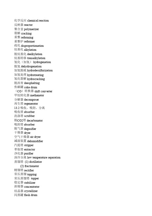
化学反应 chemical reaction反映器 reactor聚合釜 polymerizer裂解 cracking重整 reforming重整炉 reformer歧化 disproportionation烷基化 alkylation脱烷基化 dealkylation烷基转移 transalkylation氢化(加氢) hydrogenation脱氢 dehydrogenation加氢脱硫 hydrodesulfurization加氢处理 hydrotreating氢化裂解 hydrocracking脱沥青 deasphalting焦碳罐 coke drum(CO)转换器 shift converter甲烷转化器 methanator分解器 decomposer再生塔 regenerator13.2 吸收,吸附,分离吸收塔 absorber洗涤塔 scrubber脱CO2塔 decarbonator吸附塔 absorber脱气器 degasifier干燥器 dryer空气干燥器 air dryer减湿装置 dehumidifier汽提塔 stripper萃取塔 extractor净化器 purifier深冷分离 low temperature separation 蒸馏塔 (1) distillatior(2) fractionator精馏塔 rectifier常压蒸馏 topping常压蒸馏塔 topper稳定器 stabilizer浓缩器 concentrator结晶器 crystallizer闪蒸罐 flash drum分离器 separator湿气分离器 mist separator缓冲罐 knock-out drumAPI分离器 API separator油分离器 oil separator油水分离器 decanter沉淀器 settler13.3 热交换换热器 heat exchanger在线换热器 transfer heat exchanger 加热炉 furnace预热器 preheater再热器 reheater冷却塔 cooler深冷器 chiller再沸器 reboiler热缸吸再沸器 thermosiphon reboiler 蒸发器 evaporator汽化器 vaporizer冷凝器 condenser尾气冷凝器 vent condenser省煤器 economizer融解槽 melter浸没燃烧 submerged combustion废热锅炉 waste heat boiler辅助锅炉 auxiliary boiler13.4 其它接受器 receiver贮槽 (1) reservior(2) holder集气罐 accumulator缓冲器 buffer脉冲衰减装置 pulsation damper计量罐 (1) measuring tank(2) metering tank急冷塔 quencher喷射器 ejector升压器 booster循环器 recirculator加料器 feeder焚化炉 incinerator火炬(烟囱) flare stack惰性气体发生器 inert gas generator空分装置 air separation appratus 流体床操作 fluid-bed operation 造粒塔 prilling tower海水淡化装置 desalination plant。
脱硫英汉翻译
附录一Flue gas desulfurizationFlue gas desulfurization is commonly known as FGD and is the technology used for removing sulfur dioxide (SO2) from the exhaust flue gases of power plants that burn coal or oil to produce steam for the turbines that drive their electricity generators. The most common types of FGD contact the flue gases with an alkaline sorbent such as lime or limestone. [1][2][3] As sulfur dioxide is responsible for acid rain formation, stringent environmental protectionregulations have been enacted in many countries to limit the amount of sulfur dioxide emissions from power plants and other industrial facilities.Prior to the advent of strict environmental protection regulations, tall flue gas stacks (i.e., chimneys) were built to disperse rather than remove the sulfur dioxide emissions. However, that only led to the transport of the emissions to other regions. For that reason, a number of countries also have regulations limiting the height of flue gas stacks.For a typical conventional coal-fired power plant, FGD technology will remove up to 99 percent of the SO2 in the flue gases.∙Contents∙ 1 History∙ 2 FGD chemistry∙ 3 Types of FGD systemso 3.1 Spray towero 3.2 Spray-dryero 3.3 Dry sorbent injection∙ 4 Sulfur dioxide emission removal performance levels∙ 5 Facts and statistics∙ 6 Alternative methods of reducing sulfur dioxide emissions∙7 Sulfuric acid mist formation∙8 ReferencesHistoryMethods for removing sulfur dioxide from flues gases have been studied for over 150 years. Early concepts useful for flue gas desulfurization appear to have germinated in 1850 in England.With the construction of large-scale power plants in England in the 1920s, the problems associated with large volumes of SO2emissions began to concernthe public. The problem did not receive much attention until 1929, when the British government upheld the claim of a landowner against the Barton Electricity Works for damages to his land resulting from SO2 emissions. Shortly thereafter a press campaign was launched against the erection of power plants within the confines of London. This led to the imposition of SO2 controls on all such power plants.[4]During this period, major FGD installations went into operation in England at three power plants. The first one began operation at the Battersea Station in London in 1931. In 1935, the second one went into service at the Swansea Power Station. The third one was installed in 1938 at the Fulham Power Station. All three installations were abandoned duringWorld War II.Large-scale FGD units did not reappear in commercial operation until the 1970s, and most of the activity occurred in the United States and Japan.[4] As of June 1973, there were 42 FGD units, ranging in size from 5 to250 megawatts, in operation: 36 in Japan and 6 in the United States.[5]As of about 1999-2000, there were 678 FGD units operating worldwide (in 27 countries) producing a total of about 229 gigawatts. About 45% of that FGD capacity was in the United States, 24% in Germany, 11% in Japan and 20% in various other countries. Approximately 79% of the units, representing about 199 gigawatts of capacity, were using lime or limestone wet scrubbing. About 18% (or 25 gigawatts) utilized spray-dry scrubbers or dry sorbent injection systems.[6][7][8]FGD chemistrySO2 is an acid gas. Therefore, the most common large-scale FGD systems use an alkaline sorbent such as lime or limestone to neutralize and remove the SO2 from the flue gas. Since lime and limestone are not soluble in water, they are used either in the form of an aqueous slurry or in a dry, powdered form. When using an aqueous slurry of sorbent, the FGD system is referred to asa wet scrubber. When using a dry, powdered sorbent, the system is referred to as a dry system. An intermediate or semi-dry system is referred to asa spray-dry system.The reaction taking place in wet scrubbing using a CaCO3 (limestone) slurry produces CaSO3 (calcium sulfite) and can be expressed as:CaCO3 (solid) + SO2(gas) → CaSO3 (solid) + CO2 (gas)When wet scrubbing with a Ca(OH)2 (lime) slurry, the reaction alsoproduces CaSO3 (calcium sulfite) and can be expressed as:Ca(OH)2 (solid) + SO2(gas) → CaSO3 (solid) + H2O (liquid)When wet scrubbing with a Mg(OH)2 (magnesium hydroxide) slurry,the reaction produces MgSO3 (magnesium sulfite) and can beexpressed as:Mg(OH)2 (solid) + SO2(gas) → MgSO3 (solid) + H2O (liquid)Some FGD systems go a step further and oxidize theCaSO3 (calcium sulfite) to produce marketable CaSO4 · 2H2O(gypsum):CaSO3 (solid) + ½O2 (gas) + 2H2O (liquid) → CaSO4 · 2H2O (solid)Aqueous solutions of sodium hydroxide (known as causticsoda or simply caustic) may also be used to neutralize andremove SO2 from flue gases. However, caustic soda islimited to small-scale FGD systems, mostly in industrialfacilities other than power plants because it is moreexpensive than lime. It has the advantage that it forms asolution rather than a slurry and that makes it easier tooperate. It produces a solution of sodium sulfite or sodiumbisulfite (depending on the pH), or sodium sulfate that mustbe disposed of. This is not a problem in a paper mill forexample, where the solution can be recycled and reusedwithin the paper mill.Types of FGD systemsThe major types of large-scale, power plant FGD systemsinclude spray towers, spray dryers and dry sorbent injectionsystems.Spray towerThere are various types of wet scrubbers. For example, spraytowers, venturi scrubbers, packed towers and trayed towers. Slurries would cause serious erosion problems in a venturi scrubber because of the high speeds at the throat of the venturi section. Packed towers or trayed towers would plug up if handling slurries. For handling slurries, the spray tower is a good choice and it is in fact a commonly used choice in large-scale FGD systems.[3][9][10]Spray towers are used downstream of the particulate equipment (electrostatic precipitator or baghouse) where the flue gas contains very little, ifany, combustion fly ash. In a spray tower system, the sorbent slurry is simply injected via spray nozzles into a vertical tower where the slurry droplets are contacted with the upflowing flue gas.Part of the water in the slurry is evaporated by the hot flue gas and the flue gas becomes saturated with water vapor.The SO2 dissolves into the slurry droplets and reacts with the alkaline sorbent particles. The slurry falls to the bottom of the spray tower and is sent to a reaction tank where the reaction is completed and a neutral salt is formed. In a regenerable system, the residual slurry is recycled back for reuse in the spray tower. In a once-through system, the residual slurry is dewatered and either disposed of or oxidized to CaSO4 · 2H2O and sold as a by-product gypsum. Spray-dryerSpray-dryers are used upstream of the particulate removal equipment (electrical precipitator or baghouse) where the flue gas contains the combustion fly ash. In a spray-dryer system, the alkaline sorbent is usually lime slurry. The slurry is atomized and sprayed into a vessel as a cloud of fine bubbles where it contacts the hot flue gas. The water is completely evaporated by the hot gas and the residence time in the vessel (about 10 seconds) allows the SO2 and any other acid gases, such as SO3 and HCl, to react with the lime to form a dry powder of calcium sulfite, calcium sulfate and unreactedlime.[3][11][12]The dry powder is removed from the flue gas along with the combustion fly ash in the particulate removal equipment. Some of the solids from the particulate removal equipment (i.e., fly ash, calcium sulfite, calcium sulfate and unreacted lime) may be recycled and reused as part of the sorbent slurry.[12]Dry sorbent injectionThe dry FGD system simply injects powdered lime or limestone sorbent directly into the flue gas. As shown in the adjacent location diagram, the dry sorbent may be injected into any one of three locations: (1) the upper section of the steam generator, (2) the economizer section of the steam generator orthe ducting between the air preheater and the electrostaticprecipitator.[2][3][11][13]The powdered sorbent is pneumatically injected through lances designed to distribute the sorbent evenly across the flow path of the flue gas.When injected into the upper section of the steam generator, it should enter at a point where the temperature range is about 900 to 1200 °C. Injection into the economizer should be at a point where the temperature range is about 400 to 600 °C. Injection into the ducting between the preheater and the precipitator should be at point where the flue gas temperature is about 150 to 180 °C.[3][11] The SO2 reacts directly with the powdered sorbent and the spent sorbent is removed from the flue gas along with the combustion fly ash inthe particulate removal equipmentSulfur dioxide emission removal performance levelsPartial flue gas desulfurization (FGD) can achieve about 50-70 % removal of sulfur dioxide by the injection of dry limestone just downstream of the air preheater. The resultant solids are recovered in the electrostatic precipitators along with the fly ash.In power plants burning pulverized coal, wet flue gas desulfurization (FGD) that contacts the flue gases with lime slurries (in what are called wet lime scrubbers) can achieve 95% sulfur dioxide removal without additives and99+% removal with additives. Wet FGD has the greatest share of the FGD usage in the United States and it is commercially proven, well established technology.[14]The typical older FGD units in power plants burning pulverized coal within the United States achieve average sulfur dioxide emission levels of about 0.340 kg/MWh (0.22 lb SO2 /106Btu), which meets the level to which those units were permitted.The lowest demonstrated sulfur dioxide emission level (in 2005) for power plants burning pulverized high-sulfur coal within the United States was 1.08 kg/MWh (0.07 lb SO2 /106 Btu) and 0.046 kg/MWh (0.03 lb SO2 /106 Btu) for plants burning low-sulfur pulverized coal.[14]Facts and statisticsFlue gas desulfurization scrubbers have been applied to combustion units firing coal and oil that range in size from 5 MW to 1500 MW. ScottishPower are spending £400 million installing FGD at Longannet powerstation which has a capacity of over 2 GW. Dry scrubbers and sprayscrubbers have generally been applied to units smaller than 300 MW.Approximately 85% of the flue gas desulfurization units installed in the US are wet scrubbers, 12% are spray dry systems and 3% are dry injection systems.The highest SO2 removal efficiencies (greater than 95%) are achieved by wet scrubbers and the lowest (less than 80%) by dry scrubbers. However, the newer designs for dry scrubbers are capable of achieving efficiencies in the order of 90%.The capital, operating and maintenance costs per short ton ofSO2 removed (in 2001 US dollars) are:∙For wet scrubbers larger than 400 MW, the cost is $200 to $500 per ton∙For wet scrubbers smaller than 400 MW, the cost is $500 to $5,000 per ton∙For spray dry scrubbers larger than 200 MW, the cost is $150 to $300 per ton∙For spray dry scrubbers smaller than 200 MW, the cost is $500 to $4,000 per tonAlternative methods of reducing sulfur dioxide emissions An alternative to removing sulfur from the flue gases after burning is to remove the sulfur from the fuel before or duringcombustion. Hydrodesulfurization of fuel has been used for treating fuel oils.Fluidized bed combustion adds lime to the fuel during combustion. The lime reacts with the SO2 to form sulfates which become part of thecombustion ash.Sulfuric acid mist formationFossil fuels such as coal and oil contain significant amounts of sulfur.When burned, about 95 percent or more of the sulfur is generallyconverted to sulfur dioxide (SO2). This happens under normal conditions of temperature and of oxygen present in the flue gas. However, there are circumstances under which this may not be the case.For example, when the flue gas has too much oxygen and the SO2 isfurther oxidized to sulfur trioxide (SO3). Actually, too much oxygen is only one of the ways that SO3 is formed. Gas temperature is also an important factor. At about 800 °C, formation of SO3 is favored. Another way thatSO3 can be formed is through catalysis by trace metals in the fuel. This is particularly true for heavy fuel oil, where small amounts of vanadium are present. In whatever way that SO3 is formed, it does not behave likeSO2 in that it forms a liquid aerosolknown as sulfuric acid (H2SO4) mist that is very difficult to remove. Generally, about 1% of the sulfur dioxide will be converted to SO3. Since SO3 an acid gas, just as is SO2, it is also removed by the alkaline sorbents used in FGD systems.References1. ↑ Karl B. Schnelle and Charles A. Brown (2001). Air PollutionControl Technology>. CRC Press. ISBN 0-8493-9599-7.2. ↑2.02.1 SO2 Control Technologies (from website of the Institute ofClean Air Companies)3. ↑3.03.13.23.33.43.5 Air Pollution Control Technology Fact Sheet U.S.EPA publications EPA-452/F-03-0344. ↑4.04.1 Biondo, S.J. and Marten,J.C., A History of Flue GasDesulfurization Systems Since 1850, Journal of the Air PollutionControl Association, Vol. 27, No. 10, pp 948-961, October 1977.5. ↑ Beychok, Milton R., Coping With SO2, ChemicalEngineering/Deskbook Issue, October 21, 19746. ↑ Nolan, Paul S., Flue Gas Desulfurization Technologies forCoal-Fired Power Plants, The Babcock & Wilcox Company, U.S.,presented by Michael X. Jiang at the Coal-Tech 2000 InternationalConference, November, 2000, Jakarta, Indonesia7. ↑ Rubin, E.S., Yeh, S., Hounsell, D.A., and Taylor,M.R., Experience curves for power plant emission controltechnologies, Int. J. Energy Technology and Policy, Vol. 2, Nos. 1/2,20048. ↑ Beychok, Milton R., Comparative economics of advancedregenerable flue gas desulfurization processes, EPRI CS-1381,Electric Power Research Institute, March 19809. ↑ Wet FGD System Materials Cost Update, by M.G. Milobowski,Babcock & Wilcox (Presented at EPRI-DOE-EPA Combined UtilityAir Pollutant Control Symposium, August 1997)10. ↑ Air Pollution Control Technology Fact Sheet U.S.EPA publications EPA-452/F-03-01611. ↑11.011.111.2 IEA Clean Coal Center: Spray dry scrubbers forSO2 removal12. ↑12.012.1 Dry Flue Gas Desulfurization (FGD)Systems (FromBabcock and Wilcox website)13. ↑ Barbara Toole-O'Neil and Ohio Coal Development Office (Editors)(1998). Dry Scrubbing Technologies for Flue Gas Desulfurization.Springer. ISBN 0-7923-8346-X.14. ↑14.014.1 Dr. James Katzer et al and MIT Coal Energy StudyAdvisory Committee (2007).汉语翻译烟气脱硫烟气脱硫,就是泛指用烟气脱硫技术电厂燃烧煤、石油化工或其他工业废气中除去硫氧化物的技术。
电厂中英文对照
4FROM DEA 来自除氧器 FROM DEAERATOR
5TO WATER POOL 到水池
7 SH STEAM SYSTEM 过热蒸汽系统
1DRN TO BLDWN 疏水
LC SYSTEM C磨煤机系统
L D SYSTEM D磨煤机系统
L E SYSTEM E磨煤机系统
L F SYSTEM F磨煤机系统
24.MFT 主燃料跳闸 MAIN FUEL TRIP
5 FEED WATER SYSTEM 给水系统
1FLM COR 折焰角 FLAME CORE
2SPW MID HDR 水冷壁中间联箱 SPIRAL WALL MIDDLE HEADER
3ECO 省煤器 ECONOMISER
4SEP A A汽水分离器 SEPARATOR A
5TO SH ATT 到过热减温器 TO SUPERHEATER ATTEMPERATOR
7IDF A STALL A引风机喘振 INDUCED AIR FAN ASTALL
8IDF ABRG VIB HH1 A引风机轴承振动高高1 INDUCED AIR FAN A BEARING VIBRATION HIGH HIGH
9IDF A OIL STN SUPLY OIL TEMP H A引风机油站供油温度高 INDUCED AIR FAN A OIL STATION SUPPLY OIL TEMERATURE HIGH
14.OIL AB SYSTEM AB层油系统
15.OIL EC SYSTEM EC层油系统
16.OIL FD SYSTEM FD层油系统
要上传产品名称中英文对照1
要上传产品名称中英文对照11)烘干机设备系列:Dryer Equipment Series 转筒烘干机Rotary dryer 煤泥烘干机Coal Slime Rotary Dryer 沙子烘干机Sand Rotary Dryer 生物肥烘干机Bio-Fertilizer Dryer 高湿物料烘干机High Humidity Material Dryer2)回转窑系列:Rotary Kiln Series回转窑Rotary Kiln 冶金回转窑Metallurgy Rotary Kiln 石灰回转窑Lime Rotary Kiln 水泥回转窑Cement Rotary Kiln 活性石灰生产线Active Lime Production Line输送设备系列Conveyor Series输送机系列Conveyor皮带输送机Belt Conveyor斗式提升机 Bucket Elevator振动给料机Vibrating Feeder螺旋输送机Screw Conveyor链式输送机Chain Conveyor卧式给料机Horizontal Feeder3)除尘设备系列:Dust Catcher Equipment脱硫除尘器Desulfurization Dust Catcher 袋式脉冲除尘器Beg Pulse Dust Catcher 单筒旋风除尘器Monocular Cyclone Dust Catcher 静电除尘器Static Electricity Dust Catcher湿式除尘器wet-type dust catcher 双筒旋风除尘器Binocular,Cyclone Dust Catcher4)煤气发生炉系列:Coal Gasifier Series两段式煤气发生炉Double-Stage Coal GasifierQM-1型煤气发生炉QM-1 Coal GasifierQM-2型煤气发生炉QM-2 Coal Gasifier喷煤机Coal Spraying Machine单段煤气发生炉 Single-Stage Coal Gasifier5)冷却机设备系列Cooling Machine Series冷却机Cooling Machine6)破碎设备系列Crushing Equipment Series对辊破碎机2-Roller Crusher 颚式破碎机Jaw crusher 锤式破碎机Hammer crusher 立式复合破碎机Vertical Combination Crusher 齿辊破碎机Gear-Roller Crusher 反击破碎机Impact crusher7)选矿设备系列Ore Dressing Equipment Series球磨机Energy Saving Ball Mill 浮选机Floatation separator洗砂机Sand WashingMachine 圆盘造粒机Disk Grain Making Machine 对辊造粒机2-roller Grain Making Machine振动筛Vibrating Screen。
电厂常用术语中英文对照
电厂常用术语中英文对照电力术语中英文对照目录一、集控运行常用设备和术语缩写 (2)(一)锅炉部分 (2)(二)汽机部分 (4)(三)DEH部分 (5)(四)电气部分 (6)(五)系统分类 (6)(六)阀门 (7)(七)其它 (8)二、电厂术语——锅炉部分 (10)三、电厂术语——汽轮机部分 (27)四、电厂术语——电气专业 (59)五、电厂术语——电厂化学 (87)六、电厂术语——仪表与控制 (106)七、电厂术语——燃料 (126)八、电厂术语——综合管理部分 (136)九、电厂术语——脱硫 (165)一、集控运行常用设备和术语缩写(一)锅炉部分1、通用及煤粉炉FDF (forced draft fan)——送风机IDF (induced draft fan)——引风机PAF (primary air fan)——一次风机SAF (seal air fan)——密封风机DETF (flame detector fan)——火检风机APH (air preheater)——空气预热器DRUM (drum)——汽包ECON (economizer)——省煤器SH (superheater)——过热器CSH (ceiling superheater)——顶棚过热器PSH (platen superheater)——屏式过热器RSH (radiation superheater)——辐射过热器LSH (low temperature superheater)——低温过热器HSH (high temperature superheater)——高温过热器RH (reheater) ——再热器LRH (low temperature reheater)——低温再热器HRH (high temperature reheater)——高温再热器PRH (platen temperature reheater)——屏式再热器CB (coal bin)——煤仓SCB(side coal bin)——侧煤仓MILL (mill)——磨煤机FEED (coal feeder)——给煤机PCC (pulverized-coal collector)——细粉分离器MILLS (mill separator)——粗粉分离器PEF (powder exhaust fan)——排粉风机PCF(pulverized coal feeder)——给粉机HPA (heat primary air )——热一次风CPA (cold primary air )——冷一次风SECA (secondary air)——二次风TA (tertiary air)——三次风SA (seal air)——密封风AR (air register)——风门OILP (oil pistol)——油枪IGNT (ignition) ——点火枪FULP (fuel pump)——燃油泵FLTK (flash tank)——扩容器FURN(furnace) ——煤粉炉炉膛2、流化床锅炉HPCB(high-pressure centrifugal blower)——高压流化风机CFBB(Circulating Fluidized-bed Boiler)——循环流化床炉膛CYCS(cyclone separator)——旋风分离器UBF(U-type back-feeder) ——U形返料器ASHC(ash cooler) ——冷渣器3、余热锅炉CVB(convection bank) ——对流管束SWS(steam/water separator) ——汽水分离器WJP(Water jet pump)——射水泵WH(water heater) ——热水器EVP(evaporator) ——蒸发器OEJ(oil ejector)——注油器OFT(oil filter)——滤油器OCL(oil cooler)——冷油器窑头余热锅炉AQCB(此处AQC指air quenching cooler,为篦冷机,不是窑头的意思,但行业习惯称窑头余热炉为AQC炉) 窑尾余热锅炉SPB(此处SP指suspension preheater,为悬浮预热器,不是窑尾的意思,但行业习惯称窑尾余热炉为SP炉) (二)汽机部分HP (high pressure cylinder) ——高压缸IP (intermediate pressure cylinder) ——中压缸LP (low pressure cylinder) ——低压缸DEA (deaerator) ——除氧器COND (condenser) ——凝汽器HPH (high pressure heater) ——高压加热器LPH (low pressure heater) ——低压加热器SSH (shaft seal heater) ——轴封加热器MFP (motor-driven feed pump) ——电动给水泵SFP (steam feed pump) ——汽动给水泵V ACP (vacuum pump) ——真空泵CEP (Condensate extraction pump) ——凝结水泵DRNP (drain pump) ——疏水泵CIRP (circulating pump) ——循环泵LIFTP (lift pump) ——顶轴油泵LUBOP (lubricating oil pump) ——润滑油泵DCOP——直流润滑油泵ACOP——交流润滑油泵HPOP——高压启动油泵MAINOP——主油泵EHP——EH油泵OTANK (oil tank) ——油箱WTANK (water tank) ——水箱HEADER——联箱SSF (shaft seal fan) ——轴封风机IFF (induced-fume fan) ——排烟风机AIRCMP(air compressing engine) ——空气压缩机(三)DEH 部分TV——高压缸主汽门GV——高压缸调节门RV——中压缸主汽门IV——中压缸调节门LV——低压缸调节门(四)电气部分GEN (generator) ——发电机XFORM (transformer) ——变压器BUS (bus bar) ——母线BRK (circuit breaker) ——断路器SWITCH (isolating switch) ——隔离开关EXCT (exciter) ——励磁机PEXCT (pilot exciter) ——副励磁机(五)系统分类feed water system ——给水系统water-steam system ——汽水系统desuperheater system ——减温水系统combustion system ——燃烧系统extraction steam system ——抽汽系统heat supply system ——热网系统lubricating oil system——润滑油系统fuel oil system——燃油系统soot blower system——吹灰系统ignition system——点火系统powder manufacturing system——制粉系统drain system——疏水系统wind-fume system——风烟系统blowdown system——排污系统condensate system——凝结水系统deaerator system——除氧器系统turbine body——汽轮机本体by-pass system——旁路系统cooling water system——冷却水系统circulation water system——循环水系统vacuum system——真空系统(六)阀门shutoff valve——截止阀check valve——单向阀motorized valve——电动阀magnetic valve——电磁阀pneumatic positioner valve——气动阀flapper valve——挡板阀steam converter valve——减温减压阀fast valve——快关阀blow down valve——吹扫阀blow down valve——排污阀(七)其它CCS(coordinated control system) ——协调控制系统SIS(supervision & information system) ——监控信息系统MIS(management information system) ——管理信息系统BF(MODE)(borler follow mode) ——锅炉跟随方式TF(MODE)(turbine follow mode) ——汽轮机跟随方式CCS(MODE)(coordinated control mode) ——协调控制方式Manual Mode——手动方式BASE MODE——基本(手动)方式ULD(unit load demand) ——机组负荷指令ADS(automatic dispatch system) ——自动调度系统UM(unit master) ——单元机组主控制器BM&TM(boiler master & turbine master) ——锅炉主控制器和汽轮机主控制器BCS(boiler control system) ——锅炉控制系统TCS(turbine control system) ——汽轮机控制系统RB(run back) ——负荷返回RD(run down) ——强迫降负荷(迫降负荷)RU(run up) ——强迫升负荷(迫升负荷)FCB(fast cut back) ——快速减负荷AGC(automatic generation control) ——自动发电控制MFT(master fuel trip) ——主燃料跳闸CP MODE(constan pressure mode) ——定压方式VP MODE(variable pressure mode) ——滑压方式MCR(maximum continuous rating) ——最大连续出力ECR(economic continuous rating)——经济连续出力B-MCR(boiler maximum continuous rating) ——锅炉最大连续出力T-MCR(turbine maximum continuous rating) ——汽轮机最大连续出力MCS(modulating control system) ——模拟量控制系统FSSS(furnace safeguard supervisory system) ——炉膛安全监控系统BMS(burner management system) ——燃烧器管理系统SCS(sequential control system) ——顺序控制系统ECS(electric control system) ——电气控制系统DEH(digital electric-hydraulic control system) ——数字电液控制系统OPC(over speed control) ——超速控制AST(autostop trip) ——自动停机遮断ETS(emergence trip systems) ——危急遮断系统ATC(automatic turbine control) ——自动汽轮机程序控制TSI(turbine supervisory instrumentation) ——汽轮机监视系统PLC(programmable logic controller) ——可编程逻辑控制器SCR(selective catalytic reduction)——选择性催化还原法二、电厂术语——锅炉部分1.临界压力锅炉supercritical pressure boiler2. 亚临界压力锅炉subcritical pressure boiler3. 超高压锅炉super-high pressure boiler4. 蒸汽锅炉steam boiler5. 蒸汽发生器steam generator6. 液态排渣锅炉wet bottom boiler7. 固态排渣锅炉dry bottom boiler8. 燃煤锅炉coal-fired boiler9. 燃气锅炉Gas-fired boiler10.燃油锅炉oil-fired boiler11.自然循环锅炉natural circulation boiler12.汽包(锅筒)锅炉drum boiler13.强制循环锅炉controlled circulation boiler14.直流锅炉once-through boiler15.复合循环锅炉combined circulation boiler16.旋风炉cyclone furnace boiler17.沸腾炉fluidized bed combustion(FBC)boiler18.循环硫化床circulating fluidized bed combustion(FBC)boiler19.增压循环硫化床锅炉pressurized circulating fluidized bed combustion(PCFBC) boiler20.链条锅炉chain-grate boiler21.热水锅炉hot-water boiler22.废热(余热)锅炉water-heat boiler, heat recover steam generator(HRSG)23.启动锅炉start-up boiler24.厂用锅炉auxiliary boiler25.垃圾焚烧锅炉refuse-fired boiler, refuse incinerator27.露天锅炉outdoor boiler28.单炉膛锅炉single furnace boiler29.双炉膛锅炉twin furnace boiler30.W火焰锅炉W-flame boiler, vertical-fired boiler31.L火焰锅炉L-shape furnace boiler32.塔式锅炉tower boiler33.箱式锅炉box-type boiler34.炉墙furnace wall35. 汽包(锅筒)drum36.封头head37.汽包封头drum end plate, drum head38.下降管downcomer39.集中下降管centralized downcomer40.分散下降管distributed downcomer41.上升管riser42.管束(排)tube bundle43.管屏tube platen44.省煤器管economizer tube45.过热器管superheated tube46.再热器管reheater tube47.蛇形管coil48.吊挂管supporting tube49.引入管inlet pipe50.引出管outlet pipe51.饱和蒸汽管saturated steam pipe52.水冷壁管water wall tube53.鳍片管finned tube, fin tube, gilled tube54.内螺纹管rifled tube, grooved tube55.吸潮管moisture absorption piping56.水冷壁water wall57.膜式水冷壁membrane wall58.内螺纹水冷壁rifled tube water wall59.联箱header60.集汽联箱steam header61.卫燃带bailey wall, refractory belt62包墙管(包覆管)wall enclosure tube63.防渣管(弗斯顿管)slag screen, feston tube64.锅炉本体boiler proper65.锅炉机组boiler unit66.锅炉构架boiler structure67.炉膛boiler framework68.燃烧器furnace69.直流式燃烧器direct-flow burner70.旋流式燃烧器turbulent burner71.低NOX燃烧器low NOX burner72.摇摆式燃烧器tilting burner73.缝隙式燃烧器split burner74.燃烧室combustion chamber75.油枪oil gun torch76.风门damper77.一次风primary air78.二次风secondary air79.三次风tertiary air80.煤粉管道pulverized coal piping81.管板tube plate82.沸点boiling temperature83.过热器superheater84.前屏过热器front platen superheater85.后屏过热器rear plate superheater86.对流过热器convection superheater87.辐射过热器radiant superheater88.屏式过热器plate superheater89.顶棚过热器ceiling superheater90.包墙过热器wall enclosure superheater91.前包墙过热器front wall enclosure superheater92.后包墙过热器rear wall enclosure superheater93.侧包墙过热器side wall enclosure superheater94.吹灰器soot blower95.转动式吹灰器rotary soot bolwer96.伸缩式吹灰器retractable soot blower97.受热面积heating surface area, heat absorption area98.炉膛容积furnace volume99.炉膛热负荷furnace heat release rate, furnace heating absorption rate 100.汽水分离器steam separator, moisture separator101.起动分离器starting separator102.再循环管recirculating piping103.暖风器steam air heater104.再热器reheater105.再热器冷段primary reheater106.再热器热段final reheater107.顶棚ceiling108.省煤器economizer109.管式省煤器tube economizer110.管式空气预热器tubular air preheater111.回转式(再生式)空气预热器regenerative air preheater, rotary air preheater112.板式空气预热器plate air preheater113.空气预热器air preheater114.三分仓空气预热器trisector regenerative air preheater115.漏风系数air leakage coefficient116.漏风率air leakage ratio117.漏风系统air leakage system118.漏风试验air leakage test119.安全门safety valve120.安全门开启压力opening pressure of safety valve121.安全门回座压力safety valve reseating pressure122.安全门压力整定试验pressure setting test of safety valve 123.安全门动作压力safety valve operating pressure124.饱和蒸汽安全门saturated steam safety valve125. 过热蒸汽安全门superheated steam safety valve126.再热蒸汽安全门reheated steam safety valve127.防暴门explosion vent128.检查孔inspection hole129.事故喷水阀emergency water spray valve130.汽包事故放水阀emergency drum drain valve 131.三通阀three-way valve132.反冲洗阀back wash valve133.取样阀sampling valve134.插板gate135.给水大旁路门feedwater overall bypass valve 136.给水小旁路门feedwater individual bypass valve 137.大板梁plate girder, upper beam138.外护板outer casing139.锅炉排污blowdown140.定期排污扩容器intermittent blowdown flash tank 141.连续排污扩容器continuous blowdown flash tank 142.灰斗ash hopper143.冷灰斗bottom ash hopper, furnace hopper144.混合器mixer145.齿圈(大牙轮)ring gear, geared ring146.空调器air conditioner147.空气压缩机air compressor148.给煤机coal feeder149.皮带式给煤机belt coal feeder150.刮板式给煤机scraper coal feeder151.叶轮式给煤机paddle coal feeder152.给粉机pulverizer coal feeder153.磨煤机coal pulverizer, coal mill154.钢球磨煤机tube mill155.中速辊式磨煤机roller mill, bowl mill, disk roll mill 156.双进双出钢求磨煤机double inlet and outlet tube mill 157.中速磨煤机medium speed mill158.风扇磨煤机beater wheel mill, beater mill159.排粉风机pulverized coal exhauster160.一次风机primary air fan161. 烟气再循环风机gas recirculation fan162.送风机forced draft fan, force fan163.引风机induced draft fan, induced fan164.离心风机centrifugal fan165.轴流风机axial-flow fan166.双速风机double speed fan167.轴流静叶可调风机adjustable static-blade axial-flow fan fixed pitch axial-flow fan168.轴流动叶可调风机adjustable moving-blade axial-flow fan variable pitch axial-flow fan169.原煤斗raw coal bunker, raw coal silo170.煤粉仓pulverized coal bunker171.输粉机pulverized coal conveyer172.刮板输粉机scraper pulverized coal conveyer 173.螺旋输粉机pulverized coal screw conveyer174.粗粉分离器classifier175.细粉分离器(旋风分离器)cyclone separator 176.锁气器air lock, flap177.减速机speed reduce178.看火孔observation hole179.人孔门man hole180.重油泵heavy oil pump181.重油加热器heavy oil heater182.汽-汽热交换器biflux183.煤气罐gas tank184.膨胀补偿节expansion joint185.直吹式制粉系统direct firing pulverizing system 186.中贮式制粉系统bin storage type pulverizing system 187.锅炉效率boiler efficiency188.锅炉热力计算boiler thermodynamic calculation 189.锅炉空气动力计算boiler aerodynamic calculation 190.锅炉水循环计算boiler water circulation calculation 191.锅炉水力计算boiler hydrodynamic calculation 192.锅炉强度计算boiler strength calculation193.锅炉热平衡boiler heat balance calculation 194.正平衡法direct balance method195.反平衡法indirect balance method196.过剩空气系数excess air coefficient197.排烟温度flue gas temperature198.单位蒸量specific evaporation199.低温腐蚀low temperature corrosion200.高温腐蚀high temperature corrosion201.结渣lagging202.结垢腐蚀deposit corrosion203.飞灰磨损fly ash erosion204炉膛负压furnace draft205.最高允许温度maximum permissible temperature 206.炉膛正压furnace pressure207.水循环water circulation208.循环倍率circulation ratio209.除尘器dust collector, precipitator210.静电除尘器electrostatic precipitator211.整流装置rectifying device212.锤打装置rapping gear213.含尘浓度dust loading concentration214.煤灰细度dust fineness。
English_consise-脱硫单词缩写
全称 (abnormal) ABNORMAL (absorber) ABSORBER ADJUSTMENT (adjustment) (agitator) AGITATOR (alarm) ALARM ANALYSIS,ANALYTICAL(analysis,analytical) ANALYSIS,ANALYTICAL (bearing) BEARING BOOSTER FAN (booster fan) (broken) BROKEN (backwash) BACKWASH BLADE (blade) (blower) BLOWER (bypass) BYPASS (breaker) BREAKER (booster) BOOSTER (bunker) BUNKER (cabinet) CABINET CALIBRATION (calibration) CIRCULATION (circulation) COOL,COOLING(cool,cooling) COOL,COOLING (collect) COLLECT CLEAN,CLEANED(clean,cleaned) CLEAN,CLEANED (close) CLOSE (closed) CLOSED (compress) COMPRESS COMPRESSOR (compressor) COAGULANT, COAGULANT,COAGULATOR (common) COMMON (content) CONTENT CONVEY, (convey,conveyer) CONVEY,CONVEYER (control) CONTROL (current) CURRENT CONTROL VALVE (control,valve) CONVERTER (converter) CYLINDER (cylinder) (damper) DAMPER (defogger) DEFOGGER DEWATER, DEWATER,DEWATERING (dewater,dewatering) DISCHARGE (discharge) (dosing) DOSING DIFFERENCE PRESSURE (difference,pressure) DRAIN, (drain,drainage) DRAIN,DRAINAGE DRIVE, (drive,driner) DRIVE,DRIVER (device) DEVICE EMERGENCY (emergency) EXTRACT, EXTRACT,EXTRACTOR (extract,extractor) (flow) FLOW (feedback) FEEDBACK (feeder) FEEDER FLUE GAS DESULFURIZATION (flue gas desulfurization) FLOCCULATION (flocculation) (filter) FILTER (filtrate) FILTRATE FLUIDIZE (fluidize) (frequency) FREQUENCY (fault) FAULT
脱硫英汉翻译
附录一Flue gas desulfurizationFlue gas desulfurization is commonly known as FGD and is the technology used for removing sulfur dioxide (SO2) from the exhaust flue gases of power plants that burn coal or oil to produce steam for the turbines that drive their electricity generators. The most common types of FGD contact the flue gases with an alkaline sorbent such as lime or limestone. [1][2][3] As sulfur dioxide is responsible for acid rain formation, stringent environmental protectionregulations have been enacted in many countries to limit the amount of sulfur dioxide emissions from power plants and other industrial facilities.Prior to the advent of strict environmental protection regulations, tall flue gas stacks (i.e., chimneys) were built to disperse rather than remove the sulfur dioxide emissions. However, that only led to the transport of the emissions to other regions. For that reason, a number of countries also have regulations limiting the height of flue gas stacks.For a typical conventional coal-fired power plant, FGD technology will remove up to 99 percent of the SO2 in the flue gases.∙Contents∙ 1 History∙ 2 FGD chemistry∙ 3 Types of FGD systemso 3.1 Spray towero 3.2 Spray-dryero 3.3 Dry sorbent injection∙ 4 Sulfur dioxide emission removal performance levels∙ 5 Facts and statistics∙ 6 Alternative methods of reducing sulfur dioxide emissions∙7 Sulfuric acid mist formation∙8 ReferencesHistoryMethods for removing sulfur dioxide from flues gases have been studied for over 150 years. Early concepts useful for flue gas desulfurization appear to have germinated in 1850 in England.With the construction of large-scale power plants in England in the 1920s, the problems associated with large volumes of SO2emissions began to concernthe public. The problem did not receive much attention until 1929, when the British government upheld the claim of a landowner against the Barton Electricity Works for damages to his land resulting from SO2 emissions. Shortly thereafter a press campaign was launched against the erection of power plants within the confines of London. This led to the imposition of SO2 controls on all such power plants.[4]During this period, major FGD installations went into operation in England at three power plants. The first one began operation at the Battersea Station in London in 1931. In 1935, the second one went into service at the Swansea Power Station. The third one was installed in 1938 at the Fulham Power Station. All three installations were abandoned duringWorld War II.Large-scale FGD units did not reappear in commercial operation until the 1970s, and most of the activity occurred in the United States and Japan.[4] As of June 1973, there were 42 FGD units, ranging in size from 5 to250 megawatts, in operation: 36 in Japan and 6 in the United States.[5]As of about 1999-2000, there were 678 FGD units operating worldwide (in 27 countries) producing a total of about 229 gigawatts. About 45% of that FGD capacity was in the United States, 24% in Germany, 11% in Japan and 20% in various other countries. Approximately 79% of the units, representing about 199 gigawatts of capacity, were using lime or limestone wet scrubbing. About 18% (or 25 gigawatts) utilized spray-dry scrubbers or dry sorbent injection systems.[6][7][8]FGD chemistrySO2 is an acid gas. Therefore, the most common large-scale FGD systems use an alkaline sorbent such as lime or limestone to neutralize and remove the SO2 from the flue gas. Since lime and limestone are not soluble in water, they are used either in the form of an aqueous slurry or in a dry, powdered form. When using an aqueous slurry of sorbent, the FGD system is referred to asa wet scrubber. When using a dry, powdered sorbent, the system is referred to as a dry system. An intermediate or semi-dry system is referred to asa spray-dry system.The reaction taking place in wet scrubbing using a CaCO3 (limestone) slurry produces CaSO3 (calcium sulfite) and can be expressed as:CaCO3 (solid) + SO2(gas) → CaSO3 (solid) + CO2 (gas)When wet scrubbing with a Ca(OH)2 (lime) slurry, the reaction alsoproduces CaSO3 (calcium sulfite) and can be expressed as:Ca(OH)2 (solid) + SO2(gas) → CaSO3 (solid) + H2O (liquid)When wet scrubbing with a Mg(OH)2 (magnesium hydroxide) slurry,the reaction produces MgSO3 (magnesium sulfite) and can beexpressed as:Mg(OH)2 (solid) + SO2(gas) → MgSO3 (solid) + H2O (liquid)Some FGD systems go a step further and oxidize theCaSO3 (calcium sulfite) to produce marketable CaSO4 · 2H2O(gypsum):CaSO3 (solid) + ½O2 (gas) + 2H2O (liquid) → CaSO4 · 2H2O (solid)Aqueous solutions of sodium hydroxide (known as causticsoda or simply caustic) may also be used to neutralize andremove SO2 from flue gases. However, caustic soda islimited to small-scale FGD systems, mostly in industrialfacilities other than power plants because it is moreexpensive than lime. It has the advantage that it forms asolution rather than a slurry and that makes it easier tooperate. It produces a solution of sodium sulfite or sodiumbisulfite (depending on the pH), or sodium sulfate that mustbe disposed of. This is not a problem in a paper mill forexample, where the solution can be recycled and reusedwithin the paper mill.Types of FGD systemsThe major types of large-scale, power plant FGD systemsinclude spray towers, spray dryers and dry sorbent injectionsystems.Spray towerThere are various types of wet scrubbers. For example, spraytowers, venturi scrubbers, packed towers and trayed towers. Slurries would cause serious erosion problems in a venturi scrubber because of the high speeds at the throat of the venturi section. Packed towers or trayed towers would plug up if handling slurries. For handling slurries, the spray tower is a good choice and it is in fact a commonly used choice in large-scale FGD systems.[3][9][10]Spray towers are used downstream of the particulate equipment (electrostatic precipitator or baghouse) where the flue gas contains very little, ifany, combustion fly ash. In a spray tower system, the sorbent slurry is simply injected via spray nozzles into a vertical tower where the slurry droplets are contacted with the upflowing flue gas.Part of the water in the slurry is evaporated by the hot flue gas and the flue gas becomes saturated with water vapor.The SO2 dissolves into the slurry droplets and reacts with the alkaline sorbent particles. The slurry falls to the bottom of the spray tower and is sent to a reaction tank where the reaction is completed and a neutral salt is formed. In a regenerable system, the residual slurry is recycled back for reuse in the spray tower. In a once-through system, the residual slurry is dewatered and either disposed of or oxidized to CaSO4 · 2H2O and sold as a by-product gypsum. Spray-dryerSpray-dryers are used upstream of the particulate removal equipment (electrical precipitator or baghouse) where the flue gas contains the combustion fly ash. In a spray-dryer system, the alkaline sorbent is usually lime slurry. The slurry is atomized and sprayed into a vessel as a cloud of fine bubbles where it contacts the hot flue gas. The water is completely evaporated by the hot gas and the residence time in the vessel (about 10 seconds) allows the SO2 and any other acid gases, such as SO3 and HCl, to react with the lime to form a dry powder of calcium sulfite, calcium sulfate and unreactedlime.[3][11][12]The dry powder is removed from the flue gas along with the combustion fly ash in the particulate removal equipment. Some of the solids from the particulate removal equipment (i.e., fly ash, calcium sulfite, calcium sulfate and unreacted lime) may be recycled and reused as part of the sorbent slurry.[12]Dry sorbent injectionThe dry FGD system simply injects powdered lime or limestone sorbent directly into the flue gas. As shown in the adjacent location diagram, the dry sorbent may be injected into any one of three locations: (1) the upper section of the steam generator, (2) the economizer section of the steam generator orthe ducting between the air preheater and the electrostaticprecipitator.[2][3][11][13]The powdered sorbent is pneumatically injected through lances designed to distribute the sorbent evenly across the flow path of the flue gas.When injected into the upper section of the steam generator, it should enter at a point where the temperature range is about 900 to 1200 °C. Injection into the economizer should be at a point where the temperature range is about 400 to 600 °C. Injection into the ducting between the preheater and the precipitator should be at point where the flue gas temperature is about 150 to 180 °C.[3][11] The SO2 reacts directly with the powdered sorbent and the spent sorbent is removed from the flue gas along with the combustion fly ash inthe particulate removal equipmentSulfur dioxide emission removal performance levelsPartial flue gas desulfurization (FGD) can achieve about 50-70 % removal of sulfur dioxide by the injection of dry limestone just downstream of the air preheater. The resultant solids are recovered in the electrostatic precipitators along with the fly ash.In power plants burning pulverized coal, wet flue gas desulfurization (FGD) that contacts the flue gases with lime slurries (in what are called wet lime scrubbers) can achieve 95% sulfur dioxide removal without additives and99+% removal with additives. Wet FGD has the greatest share of the FGD usage in the United States and it is commercially proven, well established technology.[14]The typical older FGD units in power plants burning pulverized coal within the United States achieve average sulfur dioxide emission levels of about 0.340 kg/MWh (0.22 lb SO2 /106Btu), which meets the level to which those units were permitted.The lowest demonstrated sulfur dioxide emission level (in 2005) for power plants burning pulverized high-sulfur coal within the United States was 1.08 kg/MWh (0.07 lb SO2 /106 Btu) and 0.046 kg/MWh (0.03 lb SO2 /106 Btu) for plants burning low-sulfur pulverized coal.[14]Facts and statisticsFlue gas desulfurization scrubbers have been applied to combustion units firing coal and oil that range in size from 5 MW to 1500 MW. ScottishPower are spending £400 million installing FGD at Longannet powerstation which has a capacity of over 2 GW. Dry scrubbers and sprayscrubbers have generally been applied to units smaller than 300 MW.Approximately 85% of the flue gas desulfurization units installed in the US are wet scrubbers, 12% are spray dry systems and 3% are dry injection systems.The highest SO2 removal efficiencies (greater than 95%) are achieved by wet scrubbers and the lowest (less than 80%) by dry scrubbers. However, the newer designs for dry scrubbers are capable of achieving efficiencies in the order of 90%.The capital, operating and maintenance costs per short ton ofSO2 removed (in 2001 US dollars) are:∙For wet scrubbers larger than 400 MW, the cost is $200 to $500 per ton∙For wet scrubbers smaller than 400 MW, the cost is $500 to $5,000 per ton∙For spray dry scrubbers larger than 200 MW, the cost is $150 to $300 per ton∙For spray dry scrubbers smaller than 200 MW, the cost is $500 to $4,000 per tonAlternative methods of reducing sulfur dioxide emissions An alternative to removing sulfur from the flue gases after burning is to remove the sulfur from the fuel before or duringcombustion. Hydrodesulfurization of fuel has been used for treating fuel oils.Fluidized bed combustion adds lime to the fuel during combustion. The lime reacts with the SO2 to form sulfates which become part of thecombustion ash.Sulfuric acid mist formationFossil fuels such as coal and oil contain significant amounts of sulfur.When burned, about 95 percent or more of the sulfur is generallyconverted to sulfur dioxide (SO2). This happens under normal conditions of temperature and of oxygen present in the flue gas. However, there are circumstances under which this may not be the case.For example, when the flue gas has too much oxygen and the SO2 isfurther oxidized to sulfur trioxide (SO3). Actually, too much oxygen is only one of the ways that SO3 is formed. Gas temperature is also an important factor. At about 800 °C, formation of SO3 is favored. Another way thatSO3 can be formed is through catalysis by trace metals in the fuel. This is particularly true for heavy fuel oil, where small amounts of vanadium are present. In whatever way that SO3 is formed, it does not behave likeSO2 in that it forms a liquid aerosolknown as sulfuric acid (H2SO4) mist that is very difficult to remove. Generally, about 1% of the sulfur dioxide will be converted to SO3. Since SO3 an acid gas, just as is SO2, it is also removed by the alkaline sorbents used in FGD systems.References1. ↑ Karl B. Schnelle and Charles A. Brown (2001). Air PollutionControl Technology>. CRC Press. ISBN 0-8493-9599-7.2. ↑2.02.1 SO2 Control Technologies (from website of the Institute ofClean Air Companies)3. ↑3.03.13.23.33.43.5 Air Pollution Control Technology Fact Sheet U.S.EPA publications EPA-452/F-03-0344. ↑4.04.1 Biondo, S.J. and Marten,J.C., A History of Flue GasDesulfurization Systems Since 1850, Journal of the Air PollutionControl Association, Vol. 27, No. 10, pp 948-961, October 1977.5. ↑ Beychok, Milton R., Coping With SO2, ChemicalEngineering/Deskbook Issue, October 21, 19746. ↑ Nolan, Paul S., Flue Gas Desulfurization Technologies forCoal-Fired Power Plants, The Babcock & Wilcox Company, U.S.,presented by Michael X. Jiang at the Coal-Tech 2000 InternationalConference, November, 2000, Jakarta, Indonesia7. ↑ Rubin, E.S., Yeh, S., Hounsell, D.A., and Taylor,M.R., Experience curves for power plant emission controltechnologies, Int. J. Energy Technology and Policy, Vol. 2, Nos. 1/2,20048. ↑ Beychok, Milton R., Comparative economics of advancedregenerable flue gas desulfurization processes, EPRI CS-1381,Electric Power Research Institute, March 19809. ↑ Wet FGD System Materials Cost Update, by M.G. Milobowski,Babcock & Wilcox (Presented at EPRI-DOE-EPA Combined UtilityAir Pollutant Control Symposium, August 1997)10. ↑ Air Pollution Control Technology Fact Sheet U.S.EPA publications EPA-452/F-03-01611. ↑11.011.111.2 IEA Clean Coal Center: Spray dry scrubbers forSO2 removal12. ↑12.012.1 Dry Flue Gas Desulfurization (FGD)Systems (FromBabcock and Wilcox website)13. ↑ Barbara Toole-O'Neil and Ohio Coal Development Office (Editors)(1998). Dry Scrubbing Technologies for Flue Gas Desulfurization.Springer. ISBN 0-7923-8346-X.14. ↑14.014.1 Dr. James Katzer et al and MIT Coal Energy StudyAdvisory Committee (2007).汉语翻译烟气脱硫烟气脱硫,就是泛指用烟气脱硫技术电厂燃烧煤、石油化工或其他工业废气中除去硫氧化物的技术。
检测报告中英文信息对照表
the lower ellipsoidal head base metal piece the upper head base metal piece the lower head base metal piece the longitudinal weld of shell the longitudinal welding piece of shell the circumferential weld of shell the longitudinal and circumferential weld of shell the top Head joint piece the under Head joint piece Double thread stud stud bolt the lower head cover joint piece the upper head melon petal joint plate the upper head watts valve joint plate the upper head base metal cover joint piece the lower spherical head welding test piece welding test plate The pipe and barrel welded joint specimens Barrel longitudinal seam welded joint specimens The under Headjoint Welded joint specimen The top and bottom pipe joint head Specimen GTAW+SMAW Procedure qualification test plate
DCS中英文对照表(缩写和全称)
分类 专设 专设 位置 位置
通设 单位
电设备 功能 功能 功能 通设 通设 通设
功能 介质 状态 状态 状态 单位 专设 介质 介质 功能
通设 位置 位置 位置 位置 功能 单位 电设备 电设备 电设备 位置 电设备 位置 功能 单位 状态 功能 功能
国电热工研究院
第1页
四川广安发电有限责任公司二期工程DCS系统英汉对照表
英文全称
分类
flange
专设
tippler
功能
feedback
功能
reverse
状态
reversal rotation
功能
mode
功能
Discharge steam
功能
discharge water
功能
Dischar drive end
位置
isolating platen
国电热工研究院
第3页
四川广安发电有限责任公司二期工程DCS系统英汉对照表
排序 F T F R R M D D D N N I S A B B P A W A L P T R V H H H H H H H H H H H H H I P C F I W O O
英文缩写 FLAN TPLR FDBK RVRS RRT MODE
功能
High
状态
high voltage standby transformer 电设备
high voltage
状态
high pressure auxiliary
专设
high pressure header
专设
high energy spark ignitor
专设
high speed
- 1、下载文档前请自行甄别文档内容的完整性,平台不提供额外的编辑、内容补充、找答案等附加服务。
- 2、"仅部分预览"的文档,不可在线预览部分如存在完整性等问题,可反馈申请退款(可完整预览的文档不适用该条件!)。
- 3、如文档侵犯您的权益,请联系客服反馈,我们会尽快为您处理(人工客服工作时间:9:00-18:30)。
脱硫系统中英文对照表NO 中文English 英文缩写A AB BC CD DGGH GGH1 D C M备用D O点DCM SPARE DO(RELAY)2 SPPA 内部D O点SPPA INTERNAL USED DO3 FGD 02 FGD024 FGD 03 FGD035 FGD 05 FGD056 石膏脱水系统Gypsum dewatering G-DW7 石膏脱水Gypsum dewatering G-DW8 石灰石制备系统LIMESTONE PREPARATION LS-PR9 旁路烟气挡板BPS DMP10 旁路挡板BPS DMP11 增压风机BUF12 石膏浆液缓冲箱G-SL TK13 石膏浆液G-SL14 吸收塔ABR15 浆液循环泵SLURRY CIRCULAR PUMP S-C-P16 循环泵Circular Pump C-P17 石膏旋流器Gypsum cyclone[ˈsa ikləun] G-C18 就地操作位置LOC19 密封空气SEAL AIR SL-A20 补给水流量调节M-U-W FL21 润滑油流量低LU-OIL F L22 出线断路器OT/BK23 工业水进水I-W IN24 高压水截止电动门HP-W V25 氧化风机OAF26 事故保安MC C 段SF MCC27 MC C 电流MCC CUR28 事故保安段SF29 废水处理W/W30 水力旋流器Hydrocyclone H-C31 废水旋流站W/W-C32 截止电动门CK-V33 进水电动门IN/W V34 出口母管排浆电动门OUT BUS PIPE OUT SLURRY OT-SL VMV35 皮带机BLT36 运行状态ON37 不可用UNUSE38 排水坑PIT39 石灰石浆液LS-SL40 石灰石LS41 皮带脱水机BLTR42 阀位反馈PO43 位置反馈POS44 终端总线TERMINAL BUS45 工厂总线O PLANT BUS46 旁路电动门BPS MV47 回路断线LOOP BROKEN BKN48 石灰石制备LS-PR49 排水坑DRN PIT50 自引罐self priming SEF51 自引灌self priming SEF52 搅拌器电机AGR53 低泄露风机电机L-LK FAN54 取样系统SAMPLING SYSTEM SM-S55 事故浆液箱EM SL TK56 事故浆液EM SL57 氧化空气Oxidation Air O-A58 加湿水Humidifier Water HUM-W59 保护动作P-ACT60 进出口IN-OT61 分析仪Analyzer ANLR62 烟尘仪DUST ANLR63 执行机构Actuator ACTR64 动调执行器CTLR65 紧急停机EMG STP66 就地/远程控制L/R CTL67 远方/就地控制R/L CTL68 发电机侧GENERATOR SIDE GEN69 充电器CHARGR70 主驱动MAS71 备用驱动STBY72 空压机Compressor CPSR73 储气罐AIR STG TK74 选择为备用SEL AS STBY75 汽轮发电机组TUR-GEN76 电动调节阀CV77 主机开MN-ENG ON78 电动对开多叶E-MT MUT-VANE79 控制柜超温CAB O-TMP80 控制柜CAB81 排浆电动门OT-SL V82 冲洗水电动门WASH VALVE W-V83 冲洗电动门WASH VALVE W-V84 电动门V85 密封水SEAL WTATER S-WTR86 开门DOOR OPNED87 回流流量R-FL88 回流管R-FL89 回流R-FL90 石膏滤液调节GYPSUM FILTRATE WATER G-FLT-W91 滤液FLT-W92 风量FL93 烟道(内侧) DU(IN)94 烟道(外侧) DU(OT)95 烟道(底侧) DU(BM)96 烟道(顶侧) DU(TP)97 事故喷淋水EM SPR-W98 PH计PH MER99 除雾器MIST100 第一级 1 ST101 正面FR102 冲洗水WSH-W103 背面BK104 第二级 2 ST105 净烟气CLG F/G106 原烟气RAW F/G107 蓄电池BATTERY BAT108 电池BATTERY BAT109 低泄露风机L-LK FAN110 烟囱CHNY111 高压水泵HP PU112 底部吹灰器BM-S-BLW113 全伸出位置开关FU-EXD SW114 高压水HP-W115 入口挡板IN-DMP116 入口挡板OT-DMP117 低泄漏风机L-LK FAN118 气动截止阀P-CHK V119 就地操作LOC120 浆液制备SL-PR121 滑行平台SLIDE PLATE SLD PLT 122 搅拌电机AGR123 错误报告ERR RPT 124 调节阀CV125 控制油CTL OIL 126 中心筒cartridge CE-CASE 127 抽气箱AIR EJECTOR BOX EJ-B128 烟气再热器FLUE GAS REHEATER REHTR129 再热器REHEATER REHTR130 搅拌器AGR131 烟气F/G132 冷却水回水CLG-W R-W 133 母管HEADER HDR134 排空ventilate VENT135 全开OPED136 全关CSED137 跳闸位置OFF138 合闸位置ON139 跳闸状态OFF140 1号机组#1141 2号机组#2142 1号机#1143 2号机#2144 1号炉#1145 2号炉#2146 密封风机SEAL/F S-F147 电机绕组MOTOR WINDING WDG148 启动指令149 启指令150 停指令STP CMD 151 停止指令152 启动程序STA PROG 153 停止程序STP PROG 154 关指令155 开指令156 合闸指令157 合闸CLS158 开状态OPNED159 启状态ON160 停状态OFF161 关状态CLSED162 启动状态ON163 停止状态OFF164 关行程CLOSE LIMIT CLS LMT 165 开行程OPN LMT 166 开力矩TRQ ON 167 关力矩TRQ OFF 168 全伸出FL-EXD 169 未关闭UN-CLSD 170 过滤布FILT CLOTH FLT-CLH 171 过滤器FILTRATE FILT172 安全线SAFE LINE SF LN 173 排放水坑DRN PIT 174 补给水MAKE UP WATER M-UP-W 175 工艺水PROCESS WATER P-W176 工业水IND-W 177 润滑水LUB-W 178 排出泵Discharge Pump DS-PU 179 给料泵FEED PUMP F-PU180 传感器transmitter TSMR 181 油站OIL ST 182 备用泵STANDBY PUMP S-PU183 电加热器HTR184 加热器HTR185 超温报警T-ALM 186 吹灰器SO-BLWR 187 推进状态ENGED 188 退出状态EXTACED 189 推进指令ENGE 190 退出指令EXTAC 191 变频器Inverter INVR192 转换器CONVERTOR CONVTR 193 前轴承FRONT BEARING F-BG194 后轴承REAR BEARING R-BG195 顶部轴承TOP T-BG196 底部轴承BOTTOM B-BG197 排气EX198 开关SW199 位置POSTION PO200 故障ERROR ER201 脱硫FGD202 状态STS203 低电压L-V204 A 相1 A 1205 B 相1 B 1206 C 相1 C 1207 A 相 A208 B 相 B209 C 相 C210 出线OUT211 低压变L-V TFR212 控制电源CONTROL POWER C-P213 输送CONVEY CVY214 分段COUP215 系统SYS216 事故EM217 馈电FD-IN218 出口OUT219 入口IN220 进口IN221 进水IN/W222 排浆OUT SL223 力矩TRQ224 滤饼FLT CAKE FI-CAKE225 洗涤WASH226 静态STAC227 主机工作MN-ENG OPER 228 综合GEN229 电流CUR230 电度MER231 电压V232 车间STN233 废水W/W234 石膏GYP235 备用电机STB-MO236 电机MTR237 浆液SL238 通讯COM239 报警ALM240 电源PWR241 维修MATN242 远程RM243 启动STA244 开启ON245 运行OPER246 低压LO-V247 模块MOD248 跳闸TRIP249 流量FLOW F250 温度TEMP T251 主机main engine MN-ENG 252 1号#1253 2号#2254 挡板DMP 255 滤布FILT CLOTH FLT-CLH 256 接收Receiving RECV 257 停止STP258 皮带BELT 259 给料FEED FEED 260 传动Conveyor CVR261 错误ERR262 管道PIPE PP263 紧急EM264 远方REMOTE RM265 厚度DEPTH DEP266 控制CTL267 调偏Sway SY268 张紧度TIGHT TIT269 偏左Sway SY LT 270 偏右Sway SY RT 271 密度Density DESY 272 浓度Density DESY 273 返回RETURN RT274 电动MV275 烟道GAS DUCT DUC 276 保护PTC277 油箱OIL TK 278 油位LVL279 压差DP280 差压DP281 顶部TOP282 底部BTM283 吹枪SO-GUN 284 压缩COMPRESS CPSR 285 管路PIPE PP286 气体GAS287 校验calibration CALB 288 烟尘DUST 289 含量Concentration CNT290 静压STAC P 291 取样SMPL292 就地LOC293 反吹R-PG 294 投油OIL FIRE 295 备用STBY 296 驱动DE297 全速FL-SPD 298 半速HF-SPD 299 速度SPD300 负荷LOAD LOAD 301 实际REAL 302 导叶BLADE BLDE 303 打开OPN304 在线ON-LN 305 空调机组A-CR 306 空调A-CONDR A-CR 307 回风管R-A PP 308 指示INDI309 保安SAFE POWER SF PW 310 失电LOSS LS311 锅炉BLR312 指令CMD 313 装置DEVICE DEV314 信号SIG315 反馈FEED BACK F-B316 MC C 段MCC 317 合318 分OPN319 至TO320 高HI321 泵PU322 遍SIDE SD323 盘PLATE PLT324 段SEG325 水WTR 326 箱TANK TK327 前FR328 后REAR RR329 管PIPE PP330 相PHS331 左LEFT LT332 右RIGHT RT333 低LOW L334 值VALUE VAL335 坑PIT 336 热HOT 337 冷COLD CD 338 大HI 339 油OIL 340 温T 341 吹PG 342 主MASTER MAS。