Sound Quality Workshop- MarkMoeller
海伦钢琴H—5P摘得2012年度最佳声学钢琴奖

龙源期刊网 海伦钢琴H—5P摘得2012年度最佳声学钢琴奖
作者:
来源:《小演奏家》2013年第01期
具有权威性的全球乐器经销商杂志《MMR》在今年最新一期杂志上刊登了《第20届经销商的选择名录》,中国民族品牌钢琴“海伦H-5P”一举摘得2012年度最佳声学钢琴奖,这一结果让众多人感到惊讶,因为一直以来kawai K-3都牢牢锁定这一奖项,在这个奖项的宝座上保持着它不可撼动的王位。
对于公司来说这是个莫大的惊喜,这是他们多年不断努力沉淀的结果,外媒评论“2012年,海伦钢琴以压倒性的优势赢得了年度最佳声学钢琴大奖。
海伦H-5P以其精细入微的做工和经典的设计摘得此项桂冠”,这无疑是对海伦钢琴的肯定。
公司表示一定会不懈追求,继续为广大消费者提供更高品质的钢琴和更优质的服务。
漫步者RTC北美版音箱电路及改进

漫步者R1000TC北美版音箱电路及改进漫步者 R1000TC北美版是目前性价比比较高的音箱之一,因成本问题有可改进之处,以尽可能地发挥出喇叭和箱体的性能,提高音质,花最少的钱,办最多的事。
我们首先来了解一下这款产品漫步者R1000TC北美版音箱音箱材质全防磁设计,12mm(和15mm)中高密度板结构规格参数频率响应 20Hz-20kHz?功率放大器峰值功率:RMS 8W×2 (@fo=1kHz, THD=10%)功率放大器信噪比:>=80dB(A计权)功率放大器失真度:THD+N<=% (@fo=1kHz,PO=4W)左右声道通道分离度:>=40dB输入灵敏度:360mV输入阻抗:20k欧姆调节方式:音量,超低音旋钮调节输入接口:双立体声RCA接口,A口高音提升A口高音提升:约9dB (@ 10KHz)低音单元:4英寸陶瓷纸盆,防磁设计高音单元:3/4英寸PV膜球顶高音扬声器,防磁设计扬声器直流阻抗:8欧姆单箱外形尺寸:150mm(宽)×228mm(高)×161mm(深)重量:约 Kg输入电源:~220V,50Hz,24W?我们改进需要用到的零件:35V μF钽电容 *4八脚运放插座 *1音频运放AD8620 *1250V μF CBB电容 *212V 双触点继电器 *1音箱卡扣接线板 *1音箱线 *2其箱体非实木,其实惠威 MK200II 拿在手上很重,也没有一丁点是实木的(亲自验证过)。
这个没有改进的必要。
如果说声音不是很好听的话,本质不是功放电路的设计问题.而是为了节约成本把分频器省略了.基本上在90年代,垃圾音箱的分频器就是一个小电容.本来2只扬声器组成的音箱,可是那样就算用1介正规分频器也得需要2个电子元件.例如8欧扬声器2000HZ的1介分频器就需要的电感和10UF无级电容组成,它的成本却最少需要15元.如果用一只电容来分频(实际分频点在9000HZ)却仅需元.这就是为什么漫步者1000声音不好听的根本原因.为充分发挥这个箱子的音质,做以下改进:1.不做任何改进如何发挥最大音质:改进请注意音源的信号电平问题,也就是音箱输入信号的强弱,过强的信号会导致削波失真,音质急剧下降。
Bose Professional PowerSpace P4300+ 四通道音频放大器说明书
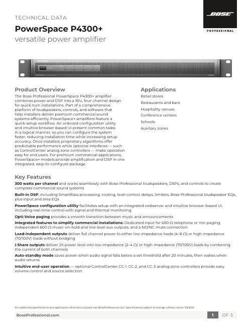
versatile power amplifierProduct OverviewThe Bose Professional PowerSpace P4300+ amplifier combines power and DSP into a 1RU, four-channel design for quick-turn installations. Part of a comprehensive platform of loudspeakers, controls, and software thathelp installers deliver premium commercial sound systems efficiently, PowerSpace+ amplifiers feature aquick-setup workflow. An onboard configuration utilityand intuitive browser-based UI present common tasksin a logical manner, so you can configure the system faster, reducing installation time while increasing setup accuracy. Once installed, proprietary algorithms offer predictable performance while optional interfaces — such as ControlCenter analog zone controllers — make operation easy for end users. For premium commercial applications, PowerSpace+ models provide amplification and DSP in one integrated, easy-to-configure package.Applications Retail stores Restaurants and bars Hospitality venues Conference centers SchoolsAuxiliary zonesKey Features300 watts per channel and works seamlessly with Bose Professional loudspeakers, DSPs, and controls to create complete commercial sound systemsBuilt-in DSP, including SmartBass processing, routing, level control, delays, limiters, Bose Professional loudspeaker EQs, plus input and area EQsPowerSpace configuration utility facilitates setup with an integrated webserver and intuitive browser-based UI, including real-time control with signal and thermal monitoringOpti-Voice paging provides a smooth transition between music and announcementsIntegrated features to simplify commercial installations: Dedicated input for 600 Ω telephone or mic paging, independent 600 Ω music-on-hold and line-level aux outputs, and a NO/NC mute connectionLoad-independent outputs deliver full channel power to either low-impedance loads (4–8 Ω) or high-impedance(70/100V) loads without bridgingI-Share outputs deliver 2X power level into low-impedance (2–4 Ω) or high-impedance (70/100V) loads by combining the current of both channelsAuto-standby mode saves power when audio signal falls below a set threshold after 20 minutes, then wakes when audio returnsIntuitive end-user operation — optional ControlCenter CC-1, CC-2, and CC-3 analog zone controllers provide easy volume control and source selectionversatile power amplifier Technical Specificationsversatile power amplifierversatile power amplifier1.Power switch – In/Out standby mode2. Power LEDSolid white LED indicates power is on.Blinking white LED indicates the unit is in auto standby mode.Solid red LED indicates a power supply fault.Blinking red LED indicates a thermal fault.3. Input 1, 2, 3, 4 signal LED – Each LED operatesindependently:Green LED indicates signal is present.Amber LED indicates signal is near clipping.Red LED indicates clipping.4. Output 1, 2, 3, 4 limit LED – Each LED operatesindependently:LED is amber when the amplifier is limiting the corresponding output due to exceeding the outputs’ V Peak or V RMS limits.LEDs will display solid red if an amplifier fault is detected.LEDs will blink red when all outputs are muted.1.Output attenuation 1, 2, 3, 4 – Output attenuators for each output. Turn the controls clockwise to decrease attenuation and counter-clockwise to increase attenuation.2. ControlCenter – RJ-45 input connector for BoseProfessional ControlCenter CC-1, CC-2, CC-3 analog zone controllers or CV41 4-to-1 converter only.3. Mute – Contact closure connection where a shortacross the mute connector will mute all outputs. Mute polarity can be inverted by a DIP switch.4. Output – 8-terminal block connector for loudspeakerconnections. Each channel can deliver up to 300 watts regardless of load into 4 Ω, 8 Ω, 70V, or 100V. Each output pair can be I-Shared.5. Ethernet – Connect amplifier to a switch or laptopEthernet port to configure via the web-based configuration utility.6. Music-on-hold – Dedicated 600 Ω music-on-holdinterface.7. Auxiliary output – Line-level auxiliary output.8. Input – Inputs 1 and 2 support balanced line-levelinputs (Euroblock) or unbalanced inputs (stereo RCA). Inputs 3 and 4 are balanced inputs, and Input 4 also supports either a 600 Ω telephone paging input or a PTT/VOX dynamic microphone input.9. AC inlet – Removing the AC cord when the amplifier ison is equivalent to powering down using the front panelpower switch and is an acceptable power-down method.Front PanelRear Panelversatile power amplifierPowerSpace, Opti-Voice, and SmartBass are trademarks of Transom Post OpCo LLC. Bose is a trademark of Bose Corporation. All other trademarks are the property of their respective owners. ©2023 Transom Post OpCo LLC. All rights reserved.Mechanical Diagrams 11. Dimensions are shown in millimeters over inches.Front View Rear ViewLeft View Top View Bottom ViewRight View44[1.7]32[1.2]483[19.0]406[16.0]466[18.3]420[16.5]。
柏林之声单元参数详解

柏林之声单元参数详解
梅赛德斯-奔驰作为国人心目中的头部豪华品牌,无论是产品力、服务都称得上一流水准,有着豪华、高品质、极致体验的标签,在车载音响系统,奔驰同世界顶级音响系统制造商Burmester合作共同打造高品质、高享受的车内音乐环境。
Burmester(柏林之声),创立于1978年的德国,现已成为世界上最受推崇的高品质立体音响系统制造厂家之一,2013年开始,柏林之声音响首次将环绕声音响系统和高端3D环绕音响系统应用在奔驰豪华轿车上,两家世界顶级的企业从此展开了长期合作的篇章。
柏林之声音响系统业界又分为小柏林和大柏林,小柏林使用的是Burmester环绕立体音响系统,带13颗扬声器(部分车型15颗扬声器)+1个功放,分别是脚底两个低音、中置一个环绕、后面左右各一个环绕、中控左右两边各一个高音,前门各一个中音,后门各一个中高音,后备箱左侧一功放,590W功率。
大柏林使用的是Burmester高端3D环绕立体声音响系统,有源分频的28信道数字信号处理器(DSP)放大器,带26颗扬声器+1个功放,分别是脚底两个低音、中置两个扬声器、眼镜盒两个高音、前门A柱一对3D旋转高音头一对中音一对低音、后门一对旋转高音和中音,门板储物位置一对低音,顶棚四个高音(左右各一个、中间两个)三个喇叭罩,并且喇叭罩会随原车氛围灯变色,后搁板位置左右各两个,后备箱的位置有1个低音炮,1个功放,共1590W功率,提供自然、柔和、现场、增环绕、3D五种音效,体验不同演绎效果。
YAMAHA REV500效果器预置程序英汉对照

YAMAHA REV500效果器预置程序英汉对照08-09-11 10:17 发表于:《灯光音响》分类:未分类YAMAHAREV500效果器预置效果英汉对照Large Hall1清亮辉煌大厅tLarge Hall2纤细洁净大厅Empty Hall空大厅、厅堂Arena模拟比较浅的舞台New Hall染色轻的回声混响效果Wonder Hall高亮度混响效果,适用与打击乐DarkHall暗厅堂,模糊混响用于童声Church1教堂染色效果明显Church2更明快Medium Hall1中等厅堂、明亮Medium Hall2中等厅堂、厚重Concert Hall音乐厅、音感自然Small Hall1小厅堂、明亮Small Hall2小厅堂、厚实Gothic Hall隆隆作响、合唱效果。
适用于独唱声部Ballade Voc1有叙述感的长延时混响效果,适用于缓慢节奏乐曲。
明亮Ballade Voc2有叙述感的长延时混响效果,适用于缓慢节奏乐曲。
厚实Rev For Pads镶边混响,音感宽广悠长。
适用于合成器效果音色mble Rev合唱混响。
时间较短镶边效果。
音感温暖适用于人声和弦乐Chorus Reverb浓密的合唱效果。
用于钢琴、合成器音色Slapped Echo模拟老式磁带延时的混响。
用于人声与独奏乐器Flutter Hall预延时较长的门混响Kick Gate门混响。
适用于低音鼓Snare Gate门混响。
适用于响弦鼓Large Room1活跃的大房间混响明快Large Room2活跃的大房间混响音感厚实Live Gate Room活跃门混响用于鼓和吉它Live Room1房间混响远距离Live Room2房间混响近距离Bath Room浴室混响效果Medium Room中等尺寸房间混响Garage车库内的混响效果Ring Studio小演播室的非线性混响[fenye]lEmpty Store空房间混响Addto DryMix直达声混响Heavy Bottom低频成份较重的混响效果Bright Room1辉煌的房间混响早期反射声明显厚重Bright Room2辉煌的房间混响早期反射声明显Small Room小房间混响效果模拟Tiny GateRoom活跃度较低的小房间混响LWood Room尺寸很小房间效果带动态滤波Soft Space混响时间较短的合唱混响适用于人声、鼓及其他独奏乐器Room Ambience小房间回声效果适用于人声、独奏乐器Tunne1长隧道混响Tunne2长隧道混响暗闷Opera大理石墙面房间混响Cathedral大理石墙面房间混响暗闷Basic Plate模仿机械震荡式钢板混响Beauty Plate厚密而亮丽钢板混响La Plate清澈而亮丽钢板混响Pelayed Spring预延时稍长的弹簧混响器混响效果Fat Plate低频更重钢板混响效果适合人声和乐器独奏Light Plate辉煌、亮丽钢板混响Thin Plate极薄的金属板混响Rev WithTail单声道混响Shore Plate时间较短稍显暗闷的钢板混响Perc Plate1时间短而明快钢板混响效果适用于打击乐Perc Plate2时间短而明快钢板混响效果适用于钹乐器Long Plate混响时间较长钢板混响特有高频成份Vocal Plate1钢板混响适用于慢节奏人声独唱[fenye]Vocal Plate2稍显暗闷钢板混响Vocalese隐约合唱效果用于吉它和键盘乐器Live Plate适用于现场表演的混响合唱混响效果可用于人声和乐器独奏MIndustrial Rev没有低频时间较短的钢板混响适用于节奏声部 Strings Space混响时间较长钢板混响音感宽广Cave低频重时间长钢板混响音感沉重适用于合成音色Super Long单声道钢板混响效果Mod Plate和声调制混响适用于吉它和键盘乐器Water Reverb镶边长时间混响效果Gate Plate门包络钢板混响用于响弦鼓Flange Room带镶边的短时间混响用于风琴和弦乐Reverb Chorus带合唱的短时间混响效果Chorus Circles带合唱的混响效果有较长的预延时Rez SweepHall类似共鸣的镶边效果其共鸣效果随输入电平而有所变化Shadow Reverb共鸣混响效果Sweep Reverb轻镶边混响Rev Flange1特效镶边效果Rev Flange特效明显镶边效果Heavy Flange镶边效果极重的镶边混响Pan Reverb带调制颤音的混响效果颤音较慢Rev Tremolo带调制颤音的混响效果颤音为中速Shake Shake方波调制颤音混响颤音速度很快CSkinny Pate带调制颤音的混响效果颤音为快速Sample Hold方波调制颤音效果颤音速度快Pan Feedback宽声像的延时反馈效果(立体声)[fenye]Long Echo带短时混响的多重回声效果Dyna Filter1动态滤波衰落时间较长DynaFilter2动态滤波衰落时间较短Dyna Filter3带共鸣效果的动态滤波Back Ward混响包络与自然混响相反的混响效果适用于鼓和吉它 Industry长预预时的早期反射混响效果NaturalGate较自然的门混响Drum FizzGate适用于处理鼓声部的门混响。
惠威HR70遥控器使用说明书

HR070 Series Remote Control Programming Guide
6. Repeat steps 1 to 5 for the other components you want to control. For future reference, write down each working component code below:
HR Series Remote Control Programming
Assigned Push-button Component Program Code
TV
CBL
SAT
AUX
DVR
Push-buttons available for Programming
Flashes during Programming
4
Used to activate Programming Mode
with the most popular code first. If the component
responds, go to step 7.
6. If the component does not respond, press LEVEL+
Push-button and the Remote Control will test
The HR70 Series Remote Controls have stored in permanent memory the necessary information to send the correct commands to the component to be controlled. By entering a five digit numeric code the commands for controlling the component is activated.
海尔电子洗衣机产品说明书
Section 6: Parts DataDC50X264310131211216547Cabinet GroupKey Part Number Description Quantity * 9960-285-008Door Assy., Loading Complete-Wht (2)* 9960-285-011Door Assy., Loading Complete-SS (2)* 9960-285-007Door Assy., Loading Complete-Chrome/BLK/SS (2)1 9960-284-002Door Assy., Loading-SS(ring only) (2)1 9960-284-004Door Assy., Loading-Chrome(ring only) (2)2 9982-353-002Plate Assy., Hinge (Wht) No Pin (2)2 9982-353-001Plate Assy., Hinge (SS) No Pin (2)* 9545-012-015Screw, Hinge to Door (8)* 8640-413-002Nut, Hinge to Door (8)3 9212-002-004Glass, Door (2)4 9206-413-002Gasket, Glass Black (2)* 9548-117-000Support, Door Glass (2)5 9206-420-005Gasket, Outer Rim Black (2)6 9244-082-001Handle, Loading Door (2)* 9545-018-017Screw, Handle 1/4-20 x 3/8 (4)* 9531-033-003Stud, Door Catch (2)* 8640-413-001Nut, Hex (2)* 8640-413-003Nut, Acorn (2)* 9086-015-002Catch, Loading Door (2)* 8638-190-009Pop Rivet for mtg. catch (4)* 8641-582-006Lockwasher (4)* 8640-399-001Spring Nut (6)7 9989-521-003Panel Assy., Front- Lower (Wht) (1)7 9989-521-001Panel Assy., Front- Lower (SS) (1)8 9989-517-003Panel Assy., Front- Upper (Wht) (1)8 9989-517-001Panel Assy., Front- Upper (SS) (1)* 9277-054-001Insulation Front Panel, half moon (top) (2)* 9277-054-002Insulation Front Panel, half moon (bottom) (2)9 9545-008-014Screw, FLHDCR, 10B x 1 (14) (6)* 8641-585-001 Lockwasher* 8640-399-001Nut, Spring (12)10 9544-069-002Strap, Hinge (Wht) (2)10 9544-069-005Strap, Hinge (SS/Black) (2)* 9545-012-028Screw, Hinge to Panel (8)11 9545-052-001Screw, Door to Hinge Strap (Special Black Type) (2)12 8641-436-003Washer, Fiber (2)13 9021-041-001Acceptor, Coin (1)* 9486-149-001Retainer, Coin Acceptor (2)14 9545-053-002Screw (4)* 9801-099-001Switch, Optical (1)Cabinet Group ContinuedKey Part Number Description Quantity15 9994-032-001Escutcheon, Upper (1)16 9435-039-002Trim, Overlay-Upper Blue (1)16 9435-039-001 Trim, Overlay-Upper Black (1)17 9994-033-001Escutcheon, Lower (1)18 9435-023-001Trim, Overlay-Lower Blue (1)18 9435-031-001Trim, Overlay-Lower Black (1)* 9545-020-009Screw (20)19 9412-167-002Nameplate Stack Dryer Express Blue (1)19 9412-167-001Nameplate Stack Dryer Express Black (1)20 9866-005-001Lint Drawer Assembly Blue (2)20 9866-005-004Lint Drawer Assembly Black (2)21 9435-024-001Overlay Trim, Lint Drwr-Blue (1)21 9435-032-001Overlay Trim, Lint Drwr-Black (1)* 9532-074-003Felt Seal ( back of lint screen assembly ) (2)* 9805-033-002Lint Screen Assembly ONLY (no front) (2)* 9555-057-008Replaceable Lint Screen Only (2)22 8650-012-004Lock and Key, Lint Drawer (2)* 6292-006-010Key 6101 only (2)* 9095-043-001Cam, Lock (2)* 9545-008-001Lint Screen Strap Hold Down Screws 10Bx 1/4 (32)23 9857-198-001Controls Assy, Blue (1)23 9857-198-003Controls Assy, Black (1)* 9627-869-001Harness, Electronic Control (1)24 8650-012-003Lock and Key, Control (1)* 9095-041-001Cam, Lock (1)* 6292-006-007Key only 6324 (1)* 9627-855-003Harness, Heat Sensor (1)* 8640-276-002Wire Nut Connector Grey (4)25 9501-004-003Sensor Temp Control (2)26 9501-008-001Bracket for Heat Sensor Mounting (Under Basket) w/ sensor..2* 9545-045-005Screw, Round Head (Mounts sensor; phillips head) (2)* 9209-037-002Gromm.et, 3/16 ID (2)* 8544-006-001Leg, Leveling 1/2” (4)* 9074-320-001 Cover, Cabinet (Top) (1)* 9277-041-017 Insulation Cabinet Cover (1)* 9732-276-001Kit for Dryers without Neutral and using 208-240 volt (1)* 9732-102-013LP Kit for 50Lb Stk Dryers (1)* 9732-243-001Stack Dryer Trunion Puller (1)* 9544-041-002 Strap - Bead Tie (1)27 9942-038-005 Vault, Coin Box (1)* 9545-008-024 Screws, Mounting-Coin Vault (2)28 9897-099-002 Coin Box Assy, Large Blue (1)28 9807-099-004 Coin Box Assy, Large Black (1)191526252792531089Control Parts GroupKey Part Number Description Quantity * 9857-198-001Controls Assy, Electronic Mounted With Membrane Switch, BLU (1)* 9857-198-003Controls Assy, Electronic Mounted With Membrane Switch, BLK (1)1 9826-008-001 Trough Assembly (1)2 9032-062-002 Button-Push, Control, Blue (2)2 9032-062-001 Button-Push, Control, Black (2)3 9538-166-011Spacer-Metal, 4mm (4)4 9486-158-001 Retainer-Push Button (2)5 8640-424-002Nut-Hex, Elastic stop, #4-40 (4)6 8652-130-038Terminal-Grounding clip (1)7 9534-365-001Spring-Flat, Control (1)8 9545-008-001Screw-Hex, #10B x 1/4 (2)9 9545-044-010 Screw-Hex, #10B x 1/4 (10)9 8641-582-005Washer-External tooth, #6 (10)10 9435-038-001Overlay-Control, Coin, Black (1)10 9435-038-002Overlay-Control, Coin, Blue (1)11 9021-041-001Acceptor-Coin, Optical (1)* 9486-149-001Retainer, Coin Acceptor (1)12 9545-053-002Screw (4)* 9801-099-001 Optical Sensor, Replacement (1)Note: Jumpers required if using 1.5 Control on Older Machines (P9 Connection)* 8220-155-001 Wire Assy, Jumper, 30Lb Stack Coin (1)* 8220-155-002 Wire Assy, Jumper, 50Lb Stack Coin (1)Door Switch GroupPart NumberDescription Quantity9539-487-001Door Switches (2)Hinge Plate Cover1 9074-340-002 Cover-Hinge, Black .....................................................................22 8636-008-010 Screw-TRHDCR, 10B x 3/8, Black.. (4)12Bearing Housing GroupKey Part Number Description Quantity J1 9241-189-002 Housing, Bearing (2)J2 9036-159-003Bearing, Ball Rear..................................................................... .2 * 9538-183-001 Spacer, Bearing (2)* 9036-159-001Bearing, Ball Front .................................................................... .2 J5 9545-017-017Bolt, 1/2 x 3/4 . (8)J7 8640-417-002Nut, 1/2 (8)* 9803-201-001Bearing Housing Complete Ass’y (includes bearings,spacer) (2)J4 9545-017-018Screw 1/2 x 1 1/2 (4)Burner Housing GroupKey Part Number Description Quantity * 9803-207-001 Housing Assembly, Burner (2)1a 9452-730-001Service Burner Plate Front... (2)1 9452-729-001 Service Plate baffl e Recirculation Chamber Clean Out (2)* 9545-008-006Screws (8)2 9545-008-001Screw (16)18 9003-220-001Angle, Burner Support (2)* 9545-008-006Screw (4)17 9048-020-002Burner, Main (4)* 9545-008-006Screw 10AB x 3/8” (4)* 9454-824-001 Panel, Back Burner Housing (2)4 9545-008-001Screw 10B x1/4” (8)5 9875-002-003Electrode Assy, Ignition (2)19 9545-045-001Screw, Electrode Mtg 8B x 1/4” (4)7 9379-186-001Valve, Gas Shut Off (1)8 9857-134-001Control Assy, Gas (2)9 9381-012-001Manifold, Assy (2)* 9425-069-021Orifi ce, Burner-Natural #27 (4)* 9425-069-022Orifi ce, Burner-LP #44 (4)10 9029-175-001Bracket, Manifold (2)22 8615-104-038Pipe Plug in end of Burner Manifold (2)* 9545-008-006Screw (4)12 9576-203-002Thermostat, Hi-Limit (2)* 9538-142-001Spacer, Hi-Limit (4)* 9545-045-007 Screw 8B x 3/4” (4)13 9074-329-001Cover, Hi-Limit Stat Ignitor (2)* 9545-008-006Screw (6)* 9576-207-008Thermostat, Safety Shutoff (2)* 9545-008-006Screw (4)15 9825-062-001Cover, Safety Stat (2)* 9545-008-024Screw (6)16 9857-116-003Control, Ignition Fenwall (3 trybox) (2)* 9732-102-013Kit, LP Conversion 50Lb Stack Kit (2)* 9838-018-003Welded One Piece Gas Pipe Assembly (1)Part # 8533-085-001 9/14Burner Housing Group Photos10221092221851A141594851613Rear ViewKey Part Number Description Quantity * 9627-861-001Wire Harness Overtemperature Switch/Air Switch (2)* 9801-098-001Switch Assy, Air Flow (2)1 9539-461-009Switch, Air Flow (2)2 9029-200-001 Bracket, Switch- Air Flow (2)3 9008-007-001Actuator, Switch (2)4 9451-169-002Pin, Cotter (2)5 9545-020-001Screw 4-40 x 5/8” (4)* 8640-401-001Nut, Special Twin .#4-40 (2)* 9550-169-003Shield, Switch (2)6 9376-322-001Motor, Drive (2)7 9452-770-001Plate, Motor Mounting (1)* 9545-029-008Bolt 3/8” - 16 x 3/4” (8)* 8641-582-003Lockwash Spring 3/8 (8)8 9545-018-019Screw, Motor Plate to Back Assy. 1/4-20x 2 1/2 (8)* 8641-582-007Lockwasher 1/4 (8)9 9538-163-006Spacr (8)* 8641-581-017Flat Washer 1/4 x 7/8 (24)* 9209-086-002Rubber Grommet (8)* 9538-166-006Grommet Spacers (8)* 9545-028-013Screw, Set (4)10 9962-018-002Back Assy, Blower Hsg (2)11 9991-053-001Support Assy, Intermed. Pulley (2)12 9545-029-010Bolt, Rd Hd 3/8-16 x 1 1/4 (6)12 8640-415-004Nut Flange Wizlock 3/8” - 16 (6)12 8641-581-035Washer, Flat (6)13 9545-029-003Bolt, 3/8-16 x 1 1/2 (2)14 9861-022-001Arm Assy-Tension, Complete (2)* 9487-200-003Ring-Retaining (6)15 9908-048-003Pulley Assy, Intermediate with bronze fl ange bearing (2)* 9036-145-002Bronze Flange Bearing (4)16 9908-047-002Pulley Driven Tumbler (2)17 9040-076-009Belt, Drive Motor (2)18 9040-073-011Belt, Driven Intermediate to Tumbler (2)19 9534-151-000Spring, Tension (2)20 9099-012-005Chain, Tension (2)21 9248-022-002Hook, Tension (2)* 9451-146-001Pin, Damper Hinge (2)* 9074-334-001 Cover Duct Upper (1)22 9973-032-001 Heat Recirculation Assembly Duct (2)* 9453-169-013Motor Pulley - Driver (1)* 9545-028-013Set Screws (2) (2)* 9278-043-001Impeller23 8641-581-026Washer, Flat 1/2” for Tumbler Pulley (2)24 9545-017-009Bolt, 1/2”-13 x 1 1/4 (2)25 8641-582-016Washer, Star 1/2” for Tumbler Pulley (2)* 9545-008-001Screw 10 Bx 1/4” (6)* 9545-014-004Bolt, 5/16-18 x 5/8” (8) (8)5/16-18* 8640-400-003Nut,* 9538-184-001Spacer, Shaft (2)* 9487-234-005Ring Tolerance (2)* 9125-007-001Damper Inside Duct Exhaust (2)* 9125-007-002Damper Inside Duct Exhaust (1)* 8520-141-000Nut, Spring (4)* 9074-335-001Cover Duct Lower (1)* 9545-008-024Screw 10ABx 3/8” (72)* 9029-173-001Bracket for Wire Harness Under Burner Housing (2)Part # 8533-085-001 9/14Part # 8533-085-001 9/14Rear View Photos1264722Rear Panel & Cover GroupKey Part Number Description Quantity19208-090-001Rear Guard Side Panel 1 (2)4 9545-008-024Screws 10 AB x 3/8 (30)5 8502-649-001Label - Connection Electrical (1)8 9208-089-001Rear Guard Back Panel (2)10 8502-600-001Label Warning & Notice (1)11 8502-645-001Label - Instructions (1)12 9109-113-001Transition Assembly Outlet (1)13 9074-320-001 Top Cover Dryer Panel (1)14 9550-188-001 Top Burner Housing Heat Shield Inlet (1)15 9074-321-001 Top Panel Burner Housing Cover (1)Part # 8533-085-001 9/141851113121514Tumbler GroupKey Part Number Description Quantity 9848-131-001Tumbler Assembly Galvanized w/spider (2)G2 9568-013-001Spider Assembly (2)G3 9497-226-002Rod, Tumbler (6)G4 8640-417-005Nut, 1/2 - 13 (6)G6 8641-590-002Washer, Special (6).............................................................................AR G7 9552-013-000Shim* 9848-130-002Tumbler Assembly Stainless Steel (2)G1 9848-130-001Tumber Assembly Galvanized (2)Part # 8533-085-001 9/14Control Assembly GroupKey Part Number DescriptionQuantity* 9857-189-001 Control Assmbly Complete (all below included) .............................1* 9108-117-001 Control Box Cover ..................................................................... 1* 8220-001-478 Wire Assembly Green 7” ............................................................ 1* 8639-621-007 Screw #10-32 x 12 Green ............................................................1* 8641-582-006 Lockwasher Ext Tooth #10 ..........................................................13 9897-026-002 Terminal Block Main Power Middle ...............................................14 9897-026-001 Terminal Block ............................................................................2* 9545-045-012 Screw #8 ABx 1/2 for terminal block ............................................6 5 8711-011-001 Transformer Ignition ...................................................................2* 9545-008-024 Screws 10AB x 3/8” ...................................................................46 9982-348-001 Plate Assembly MTG Ignition Control............................................2* 9545-008-024 Screws 10B x 1/4” MTG Above Plate and Others ...........................47 9857-116-003 Ignition Control ..........................................................................2* 8640-411-003 #6-32 Nuts ................................................................................48 9631-403-009 Wire Assembly High Voltage Upper ..............................................19 9627-860-001 Wire Harness Ignition Control Upper ............................................110 9627-860-002 Wire Harness Ignition Control Lower ............................................1* 9053-067-002 Bushing Wire 7/8” .......................................................................413 9200-001-002 Fuseholder Assembly ..................................................................314 8636-018-001 Fuse 1.5 Amp .............................................................................315 5192-299-001 Relay Power ...............................................................................216 9897-035-001 Terminal Block Assembly Main Power Inlet ...................................1* 9545-008-024 Screw #8 AB x 1/2” ....................................................................2* 8220-062-036 Wire Assembly Red/Black 14” ......................................................1* 8220-062-037 Wire Assembly Red/White 14” .....................................................1* 8220-062-038 Wire Assembly White 14” ............................................................221 9627-864-004 Wire Harness Motor Extension .....................................................2* 9527-007-001 Stand Off - Wire Saddle / Arrowhead ..........................................13* 9545-031-005 Screw 6 B x 3/8” ........................................................................422 9558-029-003 Strip Terminal Marker (Behind Input Power) ..................................124 9627-863-001 Wire Harness Main Extension Access Under Burner Housing .........123 9631-403-008 Wire Ass’y - High Voltage Lower ..................................................125 9627-859-001 Wire Harness - Main Power (1)Part # 8533-085-001 9/14Control Assembly GroupPart # 8533-085-001 9/1416252223245Coin AccecptorKey Part Number Description Quantity1 9021-041-001Coin Accecptor, Optical (1)Replacement (1)2 9801-099-001Sensor-Optical,3 9545-039-002Screw, Heighth Bar, 3mm (2)* 9486-136-001 Retainer, Coin Acceptor (1)* 9545-053-002 Screw (4)Part # 8533-085-001 9/14NotesPart # 8533-085-001 9/14NotesPart # 8533-085-001 9/14Section 7: VoltageConversionPart # 8533-085-001 9/14Part # 8533-085-001 9/14Instructions - Convert a Dual Voltage Stack Dryer from 120V to 208-240V with Neutral Wire Only1. Remove incoming power from the dryer. Use a known working voltmeter to check power.2. Remove the cover of both the upper and lower control box assemblies from the dryer using a 5/16” wrench.3. Move the black/blue wire from the N position of the main power terminal block to the L2 position of the mainpower terminal block in the upper control box assembly. See Figure 6 below.4. Move the white wire of the upper motor harness to an upper inner left terminal in the middle terminal block in thelower control box assembly. See Figure 6 below.5. Move the orange wire of the upper motor harness to an upper inner left terminal in the middle terminal block inthe lower control box assembly. See Figure 6 below.6. Move the white wire of the lower motor harness to a lower inner left terminal in the middle terminal block in thelower control box assembly. See Figure 6 below.7. Move the orange wire of the lower motor harness to a lower inner left terminal in the middle terminal block in thelower control box assembly. See Figure 6 below.8. Reconnect power to the dryer and test to ensure proper operation; one line voltage to L1, one line voltage to L2,the neutral to N, and the earth ground to E.9. Reinstall the cover of both the upper and lower control box assemblies from the dryer using a 5/16” wrench.Part # 8533-085-001 9/14NotesPart # 8533-085-001 9/14Section 9: MaintenancePart # 8533-085-001 9/14MaintenanceDaily1. Clean lint screen by unlocking and sliding out in their tracks for access. Use soft brush ifnecessary. Failure to do so will slow drying and increase gas usage and temperatures through out the dryer.2. Check lint screen for tears. Replace if necessary.Monthly1. Remove lint accumulation from end bells of motor.2. Clean lint from lint screen compartment.3. Remove lint and dirt accumulation from top of the dryer and all areas above, and around theburners and burner housing. Failure to keep this portion of the dryer clean can lead to a buildup of lint creating a fi re hazard.4. Inspect Recirculation burner housing for excessive buildup.5. Place a few drops of light oil on top and bottom pivots of the clothes door hinge.6. Grease bearings and shaft of intermediate drive pulley.Quarterly1. Check belts for looseness, wear or fraying.2. Inspect gasket of door glass for excessive wear.3. Check tightness of all fasteners holding parts to support channel.4. Check tightness of tumbler shaft retaining nut. MUST MAINTAIN 150 FOOT LBS.5. Remove lint accumulation from primary air ports in burners.6. Grease pivot pins and tension arms where in contact with each other.Semiannually1. Remove and clean main burners.2. Remove all orifi ces and examine for dirt and hole obstruction.3. Remove all lint accumulation. Remove front panel, lint screen housing and remove lintaccumulation.Annually1. Check intermediate pulley bearings for wear.2. Check and remove any lint accumulation from exhaust system.NOTE: DRYER MUST NOT BE OPERATED WITHOUT LINT SCREEN IN PLACE。
JBL Control 65P T 全范围两路挂吊型扬声器说明说明书
Key Features:᭤JBL’s exclusive conical Radiation Boundary Integrator ®(RBI) technology provides consistent and wide 120°coverage of the listening area.᭤Coaxial design featuring 130 mm (5¼ in)woofer and 20 mm (¾in) soft-dome tweeter.᭤Hanging hardware with 4.5 m (15 foot)galvanized steel cable and easy to adjust clamp.᭤Stylish design, available in black or white (-WH).᭤UL listed (speaker and hanging cable system).᭤8 ohm and 70V/100V operation.Applications:The Control 65P/T is a compact full-range,two-way pendant-type loudspeaker that provides superb sound reproduction and very consistent,wide coverage for rooms with open architecture ceilings and other locations where a pendant form factor is desired.JBL’s patent-pending Radiation Boundary Integrator ®(RBI) technology, adapted from the groundbreaking V ER T EC ™ Series of line array loudspeakers, delivers consistent coverage of the listening area. Combining a large 200 mm (8 in)diameter waveguide with low-frequencyprojection apertures, the two coaxially-mounted drivers provide a seamless integration ofcoverage, resulting in extremely even pattern control and coverage where all listeners hear a consistent, high-fidelity sound quality. The wide 120°coverage pattern allows for the use of fewer speakers, reducing the cost of theinstalled system without sacrificing performance.Excellent sound quality coupled with stylish design and easy installation makes the Control 65P/T ideal for a wide variety of applications including retail, restaurants, hotels, casinos,fitness centers, convention centers, exhibit spaces, conference rooms, atriums, museums,transit centers and other open-ceiling applications.The Control 65P/T includes a single-pointmounting system for easy and secure suspension in open-ceiling applications. Two complete hanging cable systems are included, providing both main and safety suspension cables. Include are extra-long 4.5 m (15 foot) high tensile galvanized steel wire rope having spring clips for the loudspeaker end of the cable and UL listed cable fasteners for infinitely adjustable suspension height.The system’s 130 mm (5¼in) low-frequency driver features a polypropylene-coated cone and 25 mm (1 in) copper voice coil with vented fiberglass resin coil-former for high powerhandling and improved long-term reliability. The coaxially-mounted 20 mm (¾in) textile soft-dome high frequency driver features internal damping for smooth extended response, along with an aluminum voice coil former andneodymium magnet assembly with ferro-fluid cooling, for high-fidelity sound quality with enhanced long-term sound level capability.The Control 65P/T contains a high-quality 60Watt multi-tap transformer for use on 70V/100V distributed loudspeaker lines, and is switchable for 8-ohm voice-coil direct operation.Euro-style clip-in connectors allow for easySpecifications:System:Frequency Response (-10 dB)1:55 Hz – 20 kHzFrequency Range (±3 dB)1:78 Hz – 18 kHzPower Capacity 2:75 Watts Continuous Pink Noise Power (with 300 Watts peaks)150 Watts Continuous Program PowerNominal Sensitivity:86 dBNominal Coverage Angle3:120°(+20°/-10°)Directivity (Q)3: 5.3Directivity Index (DI)3:7.2 dBRated Maximum SPL @ 1m:105 dB continuous pink noise, 111 dB peakRated Impedance:8 ohmsTransformer Taps:70V: 60W, 30W, 15W & 7.5W100V: 60W, 30W, 15WTransformer Insertion Loss:**********,0.5dB@15W,0.6dB@30W,0.7dB@60WTransducer:LF Driver:130 mm (5¼in) polypropylene-coated paper with pure butyl rubbersurround, 25 mm (1 in) copper voice coil, vented fiberglass resin voice coil-formerHF Driver:20 mm (¾in) textile soft-dome, neodymium magnet assembly,ferro-fluid cooling, aluminum voice coil formerEnclosure:Enclosure Material:High impact polystyreneGrille:Zinc-plated steel grille with powder-coat finish, foam backing(removable for painting)Environmental:Exceeds Mil Spec 810 for humidity, salt spray, temperature & UV.IP44 capability per IEC 529 – splashproof rating.Termination:Two removable locking euro-block 2-pin connectors with screw-down terminals for bare wire. Connectors paralleled for input and loop-thru. Max. wire 12 AWG (2.5 mm2). Rubber terminal covers included.Suspension:Two identical suspension systems (one as main suspension cableand the other as safety cable), each consisting of 4.5 m (15 ft) long 2 mm (0.077 in) high-tensile galvanized-steel wire rope suspension cable with spring-clips for clipping onto the loudspeaker bracket and Gripple™ brand adjustable-height cable fasteners for infinitely adjustable height. Cables have SWL rating of 45 kg (99 lb).Safety Agency Ratings:Speaker listed per UL1480, transformer registered per UL1876. Inaccordance with IEC60849/EN60849. Suspension system andGripple ®-brand cable fastener listed per UL1598 and UL2239, TUV,and CSA Class 3426-01 & Class 3426-81.Dimensions:234 mm (9.3 in) diameter x 259 mm (10.2 in) height to top ofcabinet. 279 mm (11.0 in) to top of suspension bracket.Net Weight (ea): 3.7 kg (8 lbs)Shipping Weight (pair):8.7 kg (19 lbs)IIncluded Accessories:Two suspension cable systems (see “Suspension”, above), two 2-pinremovable locking euro-block connectors, two rubber covers for euro-block connectors.Optional Accessories:MTC-PC60 top panel / terminal coverColors:Available in black or white (-WH). Paintable.Full-space (suspended)Continuous Pink Noise rating is IEC-shaped pink noise with a 6 dB peak-to-average crest factor for 100 hoursCompact Full-Range Pendant Loudspeaker with RBIProfessional SeriesControl ®65P/TShown with included grille removedSS C65᭤Control 65P/T Compact Full-Range Pendant Loudspeaker with RBI Beamwidth:-6 dB coverage by frequencyFrequency Response:Full-space, 8 ohm, 10°off-axis (typical for coverage area)Off-Axis Frequency Response:JBL Professional8500 Balboa Boulevard, P.O. Box 2200Northridge, California 91329 U.S.A.©Copyright 2010 JBL Professional。
专业音响CMARK国外音箱特点及独特的新技术
专业音响C M A R K国外音箱特点及独特的新技术Standardization of sany group #QS8QHH-HHGX8Q8-GNHHJ8-HHMHGN#专业音响 - C-MARK 国外音箱特点及独特的新技术.txt和英俊的男人握握手,和深刻的男人谈谈心,和成功的男人多交流,和普通的男人过日子。
国外音箱特点及独特的新技术1 、JBL公司音箱的特点是:承受功率大,200-300W;灵敏度高,最大声压级110dB以上;良好的频率响应,平坦的频响和优良的瞬态特性。
独特的新技术:1)音箱用低频扬声器的磁极芯相当粗,磁极芯为空心的,上面镶有线切割成型的镶片。
这种特殊设计的磁极芯可以减轻扬声器的重量,利于散热,旨在提高功率承受能力。
(2)扁线音圈作为一种先进技术,是由JBL公司发明的。
最初用在低音扬声器上,后来高音扬声器也普遍采用,铝线和铜线均有。
扁线占空系数高,磁空隙利用率高,旨在提高灵敏度。
根据测试,在同一磁路中,扁线音圈比圆线音圈可提高灵敏度约1dB。
(3)钛振膜球顶型单元,也是JBL公司首先开始成功的。
钛材料的杨氏模量比铝材料优越,使用钛膜的高频扬声器,高频上限能得到较大展宽,功率容量有较大幅度提高。
(4)SFG对称磁场磁路钛振膜是JBL公司的专利技术。
该专利技术保证了磁隙上FB值分布对称与音圈上下位置相等其中包含有磁通平衡、降低驱动源电感量和热传导的结构设置。
有效的抑制低频失真、改善功率承受能力和阻尼特性。
2、 BOSE公司该公司扬声器箱的特点是:主动利用听音环境的反射声来改善和修饰扬声器的辐射特性,开发出世界闻名的声场型扬声器箱。
bose公司的新技术:(1)直接/反射扬声器技术。
bose公司的扬声箱利用直接/反射技术还原从墙壁、天花板和地板反射到听众的混合的声音,运用直接/反射理论将声音的层次及定位表现得淋漓尽致。
代表性的产品有901,701和501型系列音箱。
(2)音响气流量低音技术。
声效和视觉值得向往的世界十大新建音乐厅
声效和视觉值得向往的世界十大新建音乐厅作者:杨志刚来源:《演艺科技》2017年第01期笔者及所在单位在从事声学设计的同时,还从中研究和总结设计中的经验和教训。
近几年通过《剧院和音乐厅音质参量的现场检测分析和评价研究》课题研究,已经对国内159座剧院、音乐厅和多功能厅进行了现场声学测试,并取得详尽的声学参量数据;同时,也收集和分析了国外120个案例,其中剧院46个、鞋盒式音乐厅46个、葡萄园式音乐厅28个,研究的案例还在持续增加中。
近几年,笔者多次赴国外著名剧院和音乐厅详细考察并观看演出,结合考察、收集的资料及多年设计经验,对于网络上经常出现的世界十大剧院或音乐厅一类的文章并不完全认同。
由此,笔者从声学和视觉美观的角度出发,选出了20世纪末以来新建的声效和视觉值得向往的十大音乐厅,供大家分享。
1 Tokyo Opera City Concert Hall(日本东京歌剧城音乐厅)一走进东京歌剧城音乐厅(以下简称TOC音乐厅),四周的原木在灯光的照射下显得金碧辉煌,金字塔式顶棚高耸,让人肃然起敬。
TOC音乐厅共1 636座,两层楼座,于1997年9月10日开幕。
值得称道的是,声学设计包含了6个基本声学参量(双耳听觉相关系数IACCE3、初始时间延迟间隙tI、中频声场力度Gmid、早期衰变时间EDT、低音比BR、表面扩散因子SDI)。
相对于以往成功的“鞋盒形”音乐厅,TOC音乐厅既借鉴了它们的成功之处,又做了一定的改进。
它的平面体型仍然采用传统的长方形,长度为33.8 m,宽度为20 m,与维也纳金色大厅相近(长35.7 m,宽19.8 m)。
但特别之处在于锥形顶棚的建筑设计(锥形顶尖离正厅地面达28 m),丰富了侧向向下的反射声,这有助于改进双耳听觉相关系数IACCE3参量。
演奏家和音乐评论员一致认为,TOC音乐厅“声音很温暖,富有围绕感和混响感、卓越的整体性,其音质与世界最佳音乐厅不相上下”。
2 Kultur- und Kongresszentrum Luzern [KKL] Luzern Concert Hall(瑞士 KKL卢塞恩音乐厅)卢塞恩文化艺术中心(KKL)周围环境十分优美,四周群山环绕,即使6月夏日炎炎,山顶依然白雪皑皑;冰山融化形成的湖水清澈见底,只见白天鹅懒散地在湖面上寻找食物。
- 1、下载文档前请自行甄别文档内容的完整性,平台不提供额外的编辑、内容补充、找答案等附加服务。
- 2、"仅部分预览"的文档,不可在线预览部分如存在完整性等问题,可反馈申请退款(可完整预览的文档不适用该条件!)。
- 3、如文档侵犯您的权益,请联系客服反馈,我们会尽快为您处理(人工客服工作时间:9:00-18:30)。
8
NVCWK3
Linear Time Invariant System (lti)
Input x(t)
System h(t)
Output y(t)
Convolution Integral Fourier Transform
y(t )
t
x( )h(t
)d
x(t )e
i t
x(t ) * h(t )dtFra bibliotekX( )
Y( )
9
H( )X ( )
NVCWK3
Simple Mechanical Oscillator Example
m
k c m = 0.5 kg k = 1000 Nt/m c = 0.5 kg/s fn = 7.12 Hz
Oscillator
cx k ( x) 0 m x
h(t ) 1 1
29
NVCWK3
Temperature (deg F)
The tiles used were designed for low temperatures. Results suggest that they performed better around 0 deg F near the SIL frequency range. No damping applied 50% damping tile coverage
13
NVCWK3
Schroeder Backwards Integration
EnvS(t )
t
h(t ) 2 dt
14
NVCWK3
Analog Reverberation Decay Method
Test Object
Shaker Switch Power Amplifier
Signal Conditioning Filter Averaging Amplifier Digital Event Recorder
22
NVCWK3
Power Injection Method
Power Input - measured
System
Power Transferred
Power Out =
tot
totEtot
=
in /
2 f Etot
23
NVCWK3
Power Injection Damping – Structural
log e d1 loge d 2 1 1 t1 log e c1 t2 c2
y ˆ b R
2
ˆ Xb
1
XX
Xy
2 2
ˆ Xy-N E y b y y-N E y
A coefficient of correlation approaching 1 suggests a good fit.
Temperature of the test part was monitored with an array of 4 thermocouples.
28
NVCWK3
Aluminum Fuselage, 50% Damping Tile Coverage
The temperature dependence of the damping tiles had a strong effect on the modal characteristic.
tot 21
NVCWK3
Random Decrement Technique
Random Decrement:
DX 0
E x(t 2 ) x(t1 )
X0
DX 0
Where
X 0 Rx ( ) / Rx (0)
Rx ( ) E x(t ) x(t )
This is also called Output Only System Identification.
Power Injection Method
in
F G
G
2 d
M v
v M Fd
2
2
24
NVCWK3
Half Power Bandwidth Method
3 dB f fr
f / fr
25
NVCWK3
Aircraft Panel Example
26
NVCWK3
The test panel was then tested in an environmental chamber to evaluate damping tile effectiveness at low temperature.
Aluminum Fuselage Section
Shaker w/ Insulation Box
27
NVCWK3
Test Set Up
Response was measured with 6 accelerometers arrayed on the panel.
Shaker input was measured with a force transducer in-line with a stinger.
Accelerometer Graphic Level Recorder
Filter Strip Chart
Signal Generator
15
NVCWK3
Filter
Purpose – Eliminate out of band information so that the measurement is not contaminated. Considerations: • Center Frequency – frequency of interest •Bandwidth - what frequencies to pass • Roll Off – how rapidly the out of band frequencies are attenuated • Group Delay – response time of the filter • ‘Ringing’ – decay rate of filter
18
NVCWK3
Filter – Impulse Response Schroeder Envelope
19
NVCWK3
Impulse Response Decay Method
Measured FRF 1 kHz 1/3 Octave Bandpass Filtered
FRFs were band-limited at every 1/3 Octave of interest for frequency dependant results.
12
NVCWK3
Hilbert Transform
The Hilbert Transform creates the analytical complement to the signal.
Adding the squares of the signal and Hilbert Transform defines the envelope of the signal.
Signal Processing Considerations
Reverberation decay technique – Analog • Band Limited White Noise • Filter • Averaging Amplifier • Graphic Level Recorder • Strip Chart Digital Processing • Digital Filter • Digital Signal Processing
4
NVCWK3
Structural Damping
• In general, a single number representation of the structural loss factors is inadequate. • Damping can depend on multiple factors. • Frequency • Temperature • Pressurization • Frequency Dependence: Standard one third octave bands are: 100, 125, 160, 200, 250, 300, 400, 500, 630, 800, 1000 ………..
Measuring Structural Damping to Support SEA Model Development
Mark Moeller, Spirit AeroSystems
SEA Models
Source Path Receiver
• SEA models track the diffusion of energy in a system. • SEA models balance damping versus diffusion. • Damping is usually measured. • A robust damping measurement is required for SEA model building.
16
NVCWK3
Filter – IIR Bandpass
4th Order Butterworth 5000 Hz Center Frequency One Third Octave Bandwidth
17
NVCWK3
Filter – Impulse Response
• Rise Time • Ringing Requirement – Filters Impulse Response must decay much faster than the physical system of interest.