科尔摩根伺服说明书
伺服技术

伺服系统伺服系统,servomechanism,是使物体的位置、方位、状态等输出被控量能够跟随输入目标(或给定值)的任意变化的自动控制系统。
伺服的主要任务是按控制命令的要求、对功率进行放大、变换与调控等处理,使驱动装置输出的力矩、速度和位置控制的非常灵活方便。
[编辑本段]基本概念伺服系统是用来精确地跟随或复现某个过程的反馈控制系统。
又称随动系统。
在很多情况下,伺服系统专指被控制量(系统的输出量)是机械位移或位移速度、加速度的反馈控制系统,其作用是使输出的机械位移(或转角)准确地跟踪输入的位移(或转角)。
伺服系统的结构组成和其他形式的反馈控制系统没有原则上的区别。
伺服系统最初用于船舶的自动驾驶、火炮控制和指挥仪中,后来逐渐推广到很多领域,特别是自动车床、天线位置控制、导弹和飞船的制导等。
采用伺服系统主要是为了达到下面几个目的:①以小功率指令信号去控制大功率负载。
火炮控制和船舵控制就是典型的例子。
②在没有机械连接的情况下,由输入轴控制位于远处的输出轴,实现远距同步传动。
③使输出机械位移精确地跟踪电信号,如记录和指示仪表等。
衡量伺服系统性能的主要指标有频带宽度和精度。
频带宽度简称带宽,由系统频率响应特性来规定,反映伺服系统的跟踪的快速性。
带宽越大,快速性越好。
伺服系统的带宽主要受控制对象和执行机构的惯性的限制。
惯性越大,带宽越窄。
一般伺服系统的带宽小于15赫,大型设备伺服系统的带宽则在1~2赫以下。
自20世纪70年代以来,由于发展了力矩电机及高灵敏度测速机,使伺服系统实现了直接驱动,革除或减小了齿隙和弹性变形等非线性因素,使带宽达到50赫,并成功应用在远程导弹、人造卫星、精密指挥仪等场所。
伺服系统的精度主要决定于所用的测量元件的精度。
因此,在伺服系统中必须采用高精度的测量元件,如精密电位器、自整角机、旋转变压器、光电编码器、光栅、磁栅和球栅等。
此外,也可采取附加措施来提高系统的精度,例如将测量元件(如自整角机)的测量轴通过减速器与转轴相连,使转轴的转角得到放大,来提高相对测量精度。
国产伺服品牌

广数,和利时电机,华大电机等等,国产自有品牌伺服。
功能简单,接口简易,多仿松下功能,以替代松下等低端日货为己任。
国内广泛采用的通用伺服品牌有:日系:三菱、安川、松下、三洋、富士、日立等;欧系:Lenze、AMK、Rexroth、KEB等;美系:Danaher(原Kollmogen)、Baldor、Parker、Rockwell等。
数控和高端运控伺服品牌:Siemens、Fanuc、三菱、Rexroth等;数控伺服情况与数控系统状况相当,Siemens和Fanuc为主,三菱次之。
国产通用伺服主要有:台达、东元、和利时、埃斯顿、时光、珠海运控、星辰伺服、步进科技等;国产数控伺服主要有:华中数控、广州数控、大森数控、凯奇数控等;国产伺服电机主要有:华大、登奇、强磁(苏强)、中源等。
国内广泛采用的通用伺服品牌有:日系:三菱、安川、松下、三洋、富士、日立等。
欧系:Lenze、AMK、Rexroth、KEB等美系:Danaher(原Kollmogen)、Baldor、Parker、Rockwell等数控和高端运控伺服品牌:Siemens、Fanuc、三菱、Rexroth等国货通用伺服:台达、东元、和利时、埃斯顿等国货数控伺服:华中、广数、大森、凯奇等国货伺服电机华大、登奇、强磁、博孚等目前通用伺服主要是日系厂家自己在拼,日系总体份额很大,估计不低于80%。
此外,台资和内资新秀们也在积极抢占市场,并有渐成气候之势。
欧系和美系产品性能明显由于日系,但价格也很高,多不是国内产业界用得起的。
数控伺服情况与数控系统状况相当,Siemens和Fanuc当道,三菱次之今天刚发现的这一家,应该是军工企业,电机规格全,国内看看除了凯奇在各类电机领域有所涉猎外,下面的这家技术实力不容小视泰安泰山新动力电机网址:自己搜吧产品类别无刷直流电机车辆牵引电机伺服电机主轴电机稀土永磁变频调速电机交流力矩电机矿山运输电机稀土永磁高效节能电机螺杆泵直驱电机磁悬浮电机井下永磁直线电机电机驱动器高速高效永磁发电机潜油电机高端异步变频电机调速系统按照性能的话一流的做伺服-LENZE,Bosch Rexroth,Baumuller,Rockwell AB,Kollmorgen,Berger Lahr,ELAU,SIEMENS,B&R,MOOG,日本的Oriental Motors和Yaskawa 的电机算是做的好的,国内的话登奇和华中电机的伺服还可以,其它一般。
伺服说明书v
Ver 2.0克瑞斯伺服驱动器使用手册台州亿丰电子有限公司1.1 产品检查 (1)1.2 产品铭牌 (2)1.3 产品前面板 (2)1.4 驱动器技术规格 (4)1.5 伺服电机安装 (4)第二章接线 (5)2.1 系统组成与接线 (5)2.2 CN1 通信接口 (8)2.3 CN2 控制接口 (9)2.4 CN3 编码器接口 (14)2.3 标准接线 (15)第三章面板操作 (16)3.1 面板组成 (16)3.2 模式功换 (17)3.3 监控模式操作 (18)3.4 辅助模式操作 (18)3.5 用户参数模式操作 (22)第四章功能参数一览表 (23)4.1 参数设置面板操作 (23)4.2 参数一览表 (23)5.1 监控面板操作 (32)5.2 监控参数一览表 (32)第六章报警及处理 (33)6.1 报警清除操作 (33)6.2 警报内容与对策表 (34)第七章 MODBUS 通信功能 (36)7.1 MODBUS 通信简介 (36)7.2 通信协议结构 (38)7.3 常用命令码 (39)7.4 伺服参数、状态信息通信地址 (47)附录 (47)附录 A 位置/速度控制模式切换 (48)附录 B 内部位置控制 (48)附录 C 输入功能控制方式选择寄存器 (50)附录 D 输入功能逻辑状态设置寄存器 (51)附录 E 输出功能状态寄存器 (51)第一章产品检查及安装1.1 产品检查本产品在出厂前均做过完整功能测试,为防止产品运送过程中因疏忽导致产品不正常,拆封后请详细检查下列事项:● 检查伺服驱动器与伺服电机型号是否与订购的机型相同。
● 检查伺服驱动器与伺服电机外观有无损坏及刮伤现象。
运送中造成损伤时请勿接线送电。
● 检查伺服驱动器与伺服电机有无零组件松脱之现象。
是否有松脱的螺丝,是否螺丝未锁紧或脱落。
● 检查伺服电机转子轴是否能以手平顺旋转。
带制动器的电机无法直接旋转。
如果上述各项有了生故障或不正常的现象,请立即与经销商联系。
AKM系列伺服电机
速度
连续运行
间歇运行
定义
Tps - 系统的峰值失速转矩 Tms - 最高速度时的峰值转矩 Tcs - 停止时的连续转矩 Tcr - 连续额定转矩(额定功率下的转矩) ωmax - 最高速度 ωr - 额定速度(额定功率下的速度) ωk - 在峰值包络拐点的速度(系统峰值
转矩和电压极限线的相交处)
驱动装置和电动机性能曲线
AKM 系列电动机目 录
2-3 4 5 6 7
8 - 14 9
10 - 11 12- 14
15 16 - 29 16 - 17 18 - 19 20 - 21 22 - 23 24 - 25 26 - 27 28 - 29 30 - 32
33 34 - 35 36 - 40
3
AKM 电动机系列简介
大量选项
本选择指南概述了该新型先进电动机系列广泛 可用的选项。使用本指南可以从大量电动机解 决方案中做出选择。我们的电动机产品由全系 列数字驱动支持,为您提供市场上可得的最佳 运动控制解决方案。
找不到您要找的东西?除了先进的 Kollmorgen 电动机系列外,科尔摩根还提供许多其它杰出 产品,从直接传动旋转和线性产品到步进电动 机和同步解决方案。科尔摩根甚至可以根据您 的需求设计正确的解决方案。您现在就可以向 我们的客户支持中心询问适合您需求的定制解 决方案。让科尔摩根的专家将大量解决方案带 到您的面前。
Kollmorgen AKM 电动机和驱动装置 –––– 无需妥协的选择
科尔摩根的新型 Kollmorgen AKM 伺服电动机和驱动装置以 广泛的标准产品为您提供前所未有的选择和灵活性,您可 以选择针对您规格的最优化伺服电动机和驱动装置组合。 选择正确的运动控制产品从未象现在这样轻松。您可以从 本产品目录说明的数以千计的伺服电动机 / 驱动装置组合中 挑选也可以访问我们的网站,找到针对您应用的最佳解决 方案。标准的 Kollmorgen AKM 伺服电动机和驱动装置两全 其美 –– 客户解决方案的精确规格,更短的交货期限以及标 准目录产品更低的成本。对于您真正独一无二的运动控制 应用,我们的工程支持团队会与您一起为您的机器设计定 制解决方案。无论是标准产品或者定制产品,您都能够选 出满足您精确要求的运动控制解决方案。
莫迪维克通过科尔摩根技术实现了气动到电气的转换

莫迪维克通过科尔摩根技术实现了气动到电气的转换更安静、更高效、操控性更强:莫迪维克采用科尔摩根伺服技术在包装机行业,越来越多的公司开始选用电气伺服技术主要是为了取代以前通过气动系统来控制运动轴。
伺服技术提高了操控性并降低了噪音排放,这些系统还帮助我们加快了生产周期,莫迪维克公司首席技术官Guido Spix 在最近一次包装展中强调到。
该包装机公司采用科尔摩根公司的运动控制解决方案来减少能源消耗,提高整机效能,并加强包装过程的安全性。
从肉类储存到成品包装等均采用电气加工。
相较于传统的以气动驱动为主的提升设备,新的R2XX 对R5XX 系列机器采用电机-驱动器组合来拉伸和密封膜安全包装:除了机器和操作人员的安全外,对于莫迪维克而言,还包括安全的包装过程。
科尔摩根伺服技术拥有的出色的可追溯性和操控性帮助莫迪维克设计出更有效的拉伸膜包装密封工艺,并提高了食品的安全性。
该解决方案目前用于高性能拉伸膜包装机,专为中大型负载设计。
优化的电机-驱动器组合。
优化的电机-驱动器组合与大多数传统的气动驱动型提升设备相比,R2XX 对R5XX 系列机器采用电机-驱动器组合来拉伸和密封膜。
这些设备利用杠杆原理提升成型模具有的重达几百公斤。
它们可承受20 吨的高的连接压力,确保两个膜密封牢固。
作为莫迪维克在运动控制方面的战略合作伙伴,科尔摩根采用AKM®伺服电机和圆形驱动器组成的紧凑装置来提升轴(kollmorgen/en-gb/products/motors/servo/servo-motors/)。
科尔摩根与莫迪维克的工程开发团队密切合作,计算并选择了最佳的电机尺寸和驱动模式。
tips:感谢大家的阅读,本文由我司收集整编。
仅供参阅!。
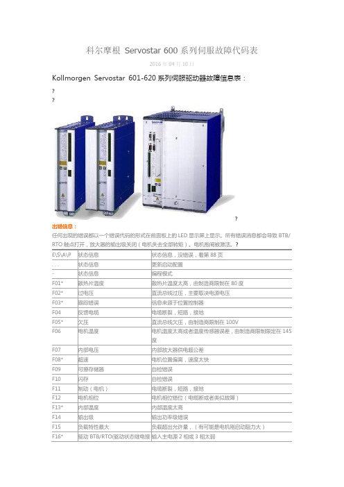
科尔摩根 Servostar 系列伺服故障代码表
S—故障
超过预设置的位置错误限
n04
响应监控
响应监控(总线)处于激活
n05
供电相位
主干线供电相位太弱
n06
SW限位开关1
低于软件限位开关1
n07
SW限位开关2
超过软件限位开关2
n08
动作任务错误
执行了一个错误动作任务
n09
没有参考点
在动作任务时(HOME设置不对)没有参考点
n10
PSTOP
PSTOP正极限限位开关激活
在温度误差被排除之前可以关闭后再检查
n23-n31
保留
?
n32
硬件测试版本
未发布版本
?
?
警告信息:?
已经发生、但不会引起放大器输出级关闭的故障(BTB/RTO 触点保持闭合),在前面板 LED 显示屏上以警告代码的形式显示。?
E.S.A.P
状态信息
状态信息,没错误,看第88页
. . .
状态信息
更新启动配置.状态信息编程模式n01
负载特性
负载接近临界值
n02
制动功率
达到预设置的制动功率限
E\S\A\P
状态信息
状态信息,没错误,看第88页
. . .
状态信息
更新启动配置
-
状态信息
编程模式
F01*
散热片温度
散热片温度太高,由制造商限制在80度
F02*
过电压
直流总线过压,主要取决电源电压
F03*
跟踪错误
信息来源于位置控制器
F04
反馈电缆
电缆断裂,短路,接地
F05*
欠压
直流总线欠压,由制造商限制在100V
AKM1x性能数据21wwwko...
采用AKD伺服驱动系统400 691 60103目录u AKM ™ 伺服电机 4u AKD ™ 伺服驱动器 8u AKM ™ 各种选件 12u AKM ™ 系统综述 13u AKM ™ 图纸和性能数据 AKM1x 18 AKM2x 22 AKM3x 26 AKM4x 30 AKM5x 36 AKM6x 42 AKM7x 46AKM8x50u L10 轴承疲劳寿命和轴负载 55u 反馈选件 58u 抱闸选件62u 伺服电机连接器选件 63u 型号命名69u MOTIONEERING ® 应用引擎71科尔摩根A K M 伺服电机选型指南克服设计、采购和时间障碍科尔摩根很清楚:如果能够帮助原始设备制造商的工程师克服遇到的障碍,就可以显著提高其工作成效。
因而,我们主要通过如下三种方式来帮助他们:集成标准和定制产品在很多情况下,最佳方案都不是一成不变的。
我们拥有专业应用知识,可以根据全面的产品组合来修改标准产品或开放全定制解决方案,从而为设计奠定良好的基础。
提供运动解决方案而不仅仅是部件在各公司减少供应商数量和工程人力的过程中,他们需要一家能够提供多种集成解决方案的全系统供应商。
科尔摩根就采用了全面响应模式,为客户提供全套解决方案,这些方案将编程软件、工程服务以及同类最佳的运动部件结合起来。
覆盖全球我们在北美、欧洲、中东和亚洲拥有众多直销、工程支持单位、制造设施以及分销商,并且临近全球各地的原始设备制造商。
这种便利优势可以加速我们的供货过程,根据客户需要随时随地供货。
财务和运营稳定性科尔摩根的母公司是价值130亿美元的丹纳赫公司。
丹纳赫业务系统是推动丹纳赫各部门发展的一个关键力量。
该系统采用“不断改善”(Kaizen )原理。
由高素质人才构成的多学科团队使用世界级的工具对过程进行评估,并制定相关计划以达到卓越的性能。
A K MT M 伺服电机5w w w.k o l l m o r g e n.c o m AKM 伺服电机的优势• 同类最佳性能• 业内领先的电机功率密度• 相同尺寸的AKM/AKD 系统的输出功率比以前增加了47%• 针对刚性和柔性传动以及连接部件进行补偿• 非常低的齿槽效应• 可以在标准产品中灵活找到完全匹配的解决方案• AKM 在统一的电机产品线中提供28种机框-机架组合以及117种标 准绕组• 200,000多种标准电机部件,其中包括多种安装、连接、反馈和其 它选件• 简化或避免了机械修改和工程适配• 成本更低的新型多圈反馈选件 • 用于AKM 的新式IP67防护等级选件• 转矩更高的新型产品,连续转矩可以达到180Nm• 使用方便,调试更快• 即插即用的电机识别驱动调试功能• 不采用传统的回零方法,从而缩短了周期时间以及传感器和连线 成本• 缩短了每个伺服系统的设置时间400 691 6010科尔摩根提供全面的电缆解决方案螺钉可选的特氟龙® 可选的轴配置锁住前轴承避免了轴向移动专利待批的F 级定子,高密度绕组,480 Vac 高压绝缘(在AKM1上为240 Vac ),采用耐用合散热的浇灌结构,155℃热敏电阻高温保护功能压铸铝壳和封盖结构多个反馈选件转(示)换器, 弦编码器可选的涂层8A K D™ 伺服驱动器9w w w.k o l l m o r g e n.c o m AKD 伺服驱动的优势• 在数秒内优化性能• 因为优化了AKM 电机绕组以精确匹配AKD ,所以将功率 密度提高了20-30%• 可以实现业内最出色、最迅速的自动调节功能。
科尔摩根KBM无框电机选型指南
EnDat2.2、01、BiSS、模拟正弦/余弦编码器、增量编码 器、HIPERFACE®以及旋转变压器。 • 紧密集成的以太网运动总线,不需要增加大型硬 件:EtherCAT®、SynqNet®、Modbus/TCP以及CANopen®。 • 可以扩展编程功能(从基本的转矩-速度到多轴主机)。
9
更多产品信息请联系销售工程师 杨里江 18911265597
AKD 伺服驱动器
AKD伺服驱动器实现了前沿的技术和性能,并且其尺寸也是业内同类产品中最小的。这些功能丰富的驱动器几 乎为所有应用系统提供了解决方案,比如说基本的转矩-速度应用、分度、以及使用嵌入式科尔摩根自动套件™ (Kollmorgen Automation Suite)的多轴可编程运动。通用的AKD产品在功率密度和性能方面设定了新的标准。
18
提供运动解决方案而不仅仅是部件
KBM 17
22
在各公司减少供应商数量和工程人力的过程中,
KBM 25
26
他们需要一家能够提供多种集成解决方案的全系
KBM 35
30
统供应商。科尔摩根就采用了全面响应模式,为
客户提供全套解决方案,这些方案将编程软件、
KBM 43
34
工程服务以及同类最佳的运动部件结合起来。
• 提供了14种机框尺寸以及多种叠片段长度。 • 采用霍尔效应传感器实现标准传感器反馈功能。 • 标准高压和低压绝缘。 • 提供多种标准绕组,并可以根据要求提供定制绕组。 • 很容易调整机械接口。
5
更多产品信息请联系销售工程师 杨里江 18911265597
K B M™ 系 列 无 框 成 套 无 刷 电 机
多摩川 手册
2
目录
第一章 产品检查及安装
1-1 产品检查 ............................................................................................................................... 5 1-1-1 伺服驱动器机种确认.................................................................................................... 5 1-1-2 伺服电机机种确认........................................................................................................ 6
直接驱动直线交流伺服电动机
蠖
一 … -, 一1 +_ ^_ 一_ J_ 1 : 一 一 一
:
_
2 徐 国 保 . 于 E ROM 的步 进 电 机 通 用 脉 冲 分 配 器 . 基 P 仪表 技 术 .
20 0 2.
( 稿 日期: 0 50— 1 收 20 —90 )
图4 15 分参 考 电 压波 形 1细
作者 简 介 : 冀
溥 , ,9 0 生 , 男 18年 山东 大 学 电气 工 程 学 院研 究 生 , 主
要从 事 特 种 电机 研 究 。
《 机 技 术 》2 0 年 第 l 电 06 期
・ 3・ 3
维普资讯
现代 驱动与控 翻
无 接触 , 维护 , 免 无刷 没计 : 相 正弦波 换 向 ; 三
美 国科 耳 摩 根 公 司 以生 产 伺 服 系 统 闻 名 于
( 动子 )科 尔摩 根生产 的D 系列直线 电动机有两 。 DL
世, 多年前开发了直流直线伺服 电动机。 随着交流 伺服系统技术的发展 ,年前叉开发了高精度、 2 免
维 护 、 推 力 的 以交流 伺 服 放 大器 驱 动 的无 刷 直 大
应注意:
() 2 宽的速度范 围: 电动机 是无接触式 , 没有 机械传递的限制, 很容易实现高速和极低速。 D D L 系列应用速度 可大于5 /, m s或低于l m s滚珠丝 g / 。 杠因共振和磨损达不到这样高的速度( 一般为05 .
m/ ̄ .m/)此 外 , 线 电动 机 具有 优 良的 速度 s07 s 。 直
和 宽速度 范 围场 合 。
无刷伺服 电动机换向需要反馈元件。 D 系 D L 列采用数字式或线性霍尔元件提供 电子换向。 选 用科尔摩根的S 或R L O O 系列伺服放大器, 电动 为 机提供6 步换 向和方波驱动电流, 用于特性可 以接 受的某些场合 。 需要特别平滑的运动, 可以选用科 尔摩根的伺服之星放大器 , 提供正弦波驱动 电流 以获得最佳的恒定推力和速度特性 。 也可由直线 编码器获得换向信息, 反馈元件可选用感应 同步 器、 激光干涉仪等。 按照直线伺服电动机要求选用伺服放大器时
- 1、下载文档前请自行甄别文档内容的完整性,平台不提供额外的编辑、内容补充、找答案等附加服务。
- 2、"仅部分预览"的文档,不可在线预览部分如存在完整性等问题,可反馈申请退款(可完整预览的文档不适用该条件!)。
- 3、如文档侵犯您的权益,请联系客服反馈,我们会尽快为您处理(人工客服工作时间:9:00-18:30)。
CD S YNQ N ETQ UICK S TART G UIDERevision No: 7Date: 22 December 20041. General1.1 Safety InformationOnly qualified personnel are permitted to transport, assembly, commission, and maintenance this equipment. Properly qualified personnel are persons who are familiar with the transport, assembly, installation, commissioning and operation of motors, and who have the appropriate qualifications for their jobs. The qualified personnel must know and observe the following standards and regulations:IEC 364 resp. CENELEC HD 384 or DIN VDE 0100 IEC report 664 or DIN VDE 0110National regulations for safety and accident prevention or VBG 4 •Read all available documentation before assembly and commissioning. Incorrect handling of products in this manual can result in injury and damage to persons and machinery. Strictly adhere to the technical information on the installation requirements.• It is vital to ensure that all system components are connected to earth ground. Electrical safety is impossible without a low-resistance earth connection.•The SERVOSTAR® product contains electro-statically sensitive components that can be damaged by incorrect handling. Discharge any electrical shock potential from you before touching the product. Avoid contact with high insulating materials (artificial fabrics, plastic film, etc.). Place the product on a conductive surface.• During operation keep all covers and cabinet doors shut. Otherwise, there are deadly hazards that could possibility cause severe damage to health or the product.• In operation, depending on the degree of enclosure protection, the product can have bare components that are live or have hot surfaces. Control and power cables can carry a high voltage even when the motor is not rotating. • Never pull out or plug in the product while the system is live. There is a danger of electric arcing and danger to persons and contacts.•After powering down the product, wait at least ten minutes before touching live sections of the equipment or undoing connections (e.g., contacts, screwed connections). Capacitors can store dangerous voltages for long periods of time after power has been switched off. To be safe, measure the contact points with a meter before touching.When these symbols are seen in this manual, be alert to the potential for personal injury. Follow the recommended precautions and safe operating practices included with the alert symbols. Safety notices in this manual provide important information. Read and be familiar with these instructions before attempting installation, operation, or maintenance. The purpose of this section is to alert users to possible safety hazards associated with this equipment and the precautions that need to be taken to reduce the risk of personal injury and damage to the equipment. Failure to observe these precautions could result in serious bodily injury,damage to the equipment, or operational difficulty. The safety-alert symbols are:Warning Alerts users to potential physical danger or harm. Failure to follow warning notices could result in personal injury or death.Caution Directs attention to general precautions, which if not followed, could result in personal injuryand/or equipment damage.Note Highlights information critical to your understanding or use of the product.1.2 Limited WarrantyIncludes software provided by KollmorgenSeller warrants that the Goods sold hereunder are free from defects in material and workmanship for the product warranty period of each item of Goods (Product Warranty Periods are listed below). Seller warrants its Good(s) only to the originalpurchaser (the “Customer”), and in the case of original equipment manufacturers or distributors, only to their original consumer (the “Customer”). There are no warranties whatsoever on Goods built or acquired, wholly or partially, to a buyer’s designs or specificationsThis express warranty is in lieu of and exclude all other warranties, express or implied, by operation or law or otherwiseincluding THE WARRANTY OF MERCHANTABILITY AND FITNESS FOR A PARTICULAR PURPOSE (WHETHER KNOWN TO SELLER OR NOT), all other such warranties being hereby expressly disclaimed by Seller and waived by Buyer. Written notice of claimed defects shall have been given to Seller within the period set forth in the schedule below, and within thirty (30) days from the date any such defect is first discovered.广州科沃—工控维修的120 www.gzkowo.com1.2.1 Product Warranty SchedulesBrand Products Warranty Period Kollmorgen Standard Brush-type Motors,Electronics and Accessories12 months from date of manufactureKollmorgen Standard Brushless Motors, Electronicsand Accessories24 months from date of manufactureKollmorgen Standard Step Motors, Stepper Controlsand Accessories12 months from date of manufactureKollmorgen Custom Motion Systems or componentsof any type To be negotiated on a case-by-case basis, and set forth in the order.Pacific Scientific All Products 24 months from date of manufactureSuperior All Products 12 months from date of manufactureThe Goods or parts claimed to be defective must be returned to Seller, accompanied by a Return Material Authorization (RMA) issued by Seller’s facility responsible for supplying Goods, with transportation prepaid by Customer, with written specifications of the claimed defect.If a warranty claim is valid, Seller shall pay reasonable one-way costs of transportation of the defective Goods from either the original destination or the location where defect occurred, whichever is closest to Seller’s facility. Under no circumstances shall Seller be liable for removal of Seller’s Goods from Buyer’s equipment or re-installation into Buyer's equipment.No person, including any agent, distributor, or representative of Seller, is authorized to make any representation or warranty on behalf of Seller concerning any goods manufactured by Seller, except to refer purchasers to this warranty.1.2.2 GeneralIndemnityBuyer agrees to hold Seller harmless from any and all liability, and to pay all costs and attorney’s fees, for injury or damage to persons or property caused in any manner by Goods covered by the order while in possession or under the control of Buyer or Buyer’s successor in interest.1.2.3 Use As DirectedThe following guidelines describe the restrictions for proper use of the SERVOSTAR CD SynqNet system: • The amplifiers are components built into electrical equipment or machines and can only be commissioned as integral components of such equipment.• The servo amplifiers are to be used only on earthed three-phase industrial mains supply networks (TN-system, TT-system with earthed neutral point).• The servo amplifiers must not be operated on power supply networks without an earth or with an asymmetrical earth.• If the servo amplifiers are used in residential areas, or in business or commercial premises, the user must implement additional filter measures.• The servo amplifiers are only intended to drive specific brushless synchronous servomotors from Kollmorgen with closed-loop control of torque, speed, and position. The rated voltage of the motors must be at least as high as theDC-link voltage of the servo amplifier.• The servo amplifiers may only be operated in a closed switchgear cabinet, taking into account the ambient conditions defined in the environmental specifications.Kollmorgen guarantees the conformance of the servo amplifiers with the standards for industrial areas stated in this manual only if Danaher Motion Kollmorgen delivers the components (motors, cables, amplifiers etc).1.2.4 SoftwareWarrantyComputer software programs that may be included in material or Goods sold to Buyer have been designed to perform a given set of tasks as defined in the documentation provided and are offered AS IS. It is Buyer’s responsibility to determine if the features of the software programs are suitable for Buyer’s requirements and must confirm that the software programs operate correctly. Buyer understands that such software programs are of such complexity that they may have inherent defects and that Seller makes no warranty that all software features will perform correctly as supplied. For Seller’s software utilizing automation servers, improper reading and writing data to the automation server can cause the automation server software to malfunction and may cause the automation server and/or the program writing to the automation server to crash. Improperly reading and writing data to an automation server may cause the device controlled by that automation server to malfunction. Seller shall not be responsible for damage to any device or damage caused by any device due to the improper reading and/or writing of data to an automation server.1.2.5 Limitation of liabilityNOTWITHSTANDING ANYTHING TO THE CONTRARY, SELLER SHALL NOT BE LIABLE FOR ANY SPECIAL, INCIDENTAL, INDIRECT OR CONSEQUENTIAL DAMAGES INCLUDING LOST PROFITS ARISING OUT OF THE PERFORMANCE, DELAYED PERFORMANCE OR BREACH OF PERFORMANCE OF THIS ORDER REGARDLESS WHETHER SUCH LIABILITY BE CLAIMED IN CONTRACT, EQUITY, TORT OR OTHERWISE. SELLER’S OBLIGATION ISLIMITED SOLELY TO REPAIRING OR REPLACING (AT ITS OPTION AND AS SET FORTH IN SECTION 10 AND SECTION 11), AT ITS APPROVED REPAIR FACILITY, ANY GOODS OR PARTS WHICH PROVE TO SELLER’S SATISFACTION TO BE DEFECTIVE AS A RESULT OF DEFECTIVE MATERIALS OR WORKMANSHIP, IN ACCORDANCE WITH SELLER’S STATED WARRANTY. IN NO EVENT SHALL SELLER’S LIABILITY EXCEED THE TOTAL PURCHASE PRICE SET FORTH IN THIS ORDER.number1.3 Part1.4 Where to get supportDanaher Motion is committed to quality customer service. Our goal is to provide the customer with information and resources as soon as they are needed. In order to serve in the most effective way, contact your local sales representative for order status and delivery information, product information and literature, and application and field technical assistance. If you are unaware of your local sales representative, please contact us at:Email: sep@Specify “SynqNet Support” in the subject line.1.5 Manual Download LocationComplete product manuals can be downloaded from the Danaher Motion website, at -> Customized Products -> Drives -> CD SynqNet2. Unpacking and InspectionOpen the box and remove all the contents. Check to ensure there is no visible damage to any of the equipment.Electronic components in this amplifier are design-hardened to reduce static sensitivity. However, properprocedures should be used when handling to avoid damage to equipment.Remove all packing material and equipment from the shipping container. Be aware that some connector kits and other equipment pieces may be quite small and can be accidentally discarded if care is notobserved when unpacking the equipment. Do not dispose of shipping materials until the packing list hasbeen checked.Upon receipt of the equipment, inspect components to ensure that no damage has occurred in shipment. If damage is detected, notify the carrier immediately. Check all shipping material for connector kits, documentation, diskettes, CD-ROM, or other small pieces of equipment.3. Installation Instructions3.1 GeneralThese installation steps are designed to lead you through the proper installation and setup of a SERVOSTAR CD SynqNetsystem. They were developed with the assumption that you have a fundamental understanding of basic electronics, computers, mechanics, and proper safety practices. However, you do not have to be an expert in motion control to install and operate thedrive system. It is recommended that you read the entire manual completely before attempting installation or operation.High voltage can present dangerous and hazardous conditions if not performed by a qualified electrician. Be certain to follow all national and local codes during installation.1. Open the box(es) and remove all the contents. Check to ensure there is no visible damage to any of the equipment.2. Mount the SERVOSTAR CD SynqNet to the back panel. Refer to the appropriate Outline Dimensions in this manual. Metal-to-metal contact is important for electrical noise control!3. Wire the SERVOSTAR CD SYNQNET according to the appropriate System Wiring Diagram.4. Connect solid earth ground to frames of all components.5. Wire the main power (115/230 VAC). Wire the 24 volt supply to the connector at the top of the drive.6. Wire user I/O at connector C3: At a minimum, 24 volts must be brought in to the enable circuit. Be certain that connector C3 is inserted correctly.7. Wire the motor and feedback. Refer to the Feedback Wiring Diagram for additional information. 8. Wire Regen Resistor kit, if applicable. 9.Verify that all wiring is correct.10. Verify that earth grounds are connected. 11. Verify all electrical and safety codes are met.12. Connect the SynqNet cable between the Motion Controller and connector C4.3.2 GroundingSystem grounding is essential for proper performance of the drive system. A ground bus bar may be used as a single point ground for the system. Safety grounding should be provided to all pieces of the system from a “star point." In addition to the safety grounding, a high frequency ground must be provided that connects the back panel to the enclosure and, ultimately, to earth ground. The objective is to provide an extremely low impedance path between the filters, drives, power supplies, and earth ground. This high frequency ground is accomplished with the use of a flat braid or copper bus bar. It is important not to rely on a standard wire for the high frequency ground. In general, a wire has an inductance of 8nH-per-inch, regardless of diameter. At higher frequencies, this unwanted inductance between grounds equates to limited filter performance. When connecting high frequency grounds, use the shortest braid possible.3.3 BondingThe proper bonding of shielded cables is imperative for minimizing noise emissions and increasing immunity levels of the drive system. Its effect is to reduce the impedance between the cable shield and the back panel. Kollmorgen recommends that all shielded cables be bonded to the back panel.Power input wiring does not require shielding (screening) if the power is fed to the cabinet (enclosure) via metallized conduit. If metallized conduit is not implemented into the system, shielded cable is required on the power input wires and proper bonding technologies should be implemented.The motor and feedback cables should have the shield exposed as close to the drive as possible. This exposed shield is bonded to the back panel using either non-insulated metallic cable clamps or cable bonding clamps offered by Phoenix Contact (and others).3.4 CEFilteringThe SERVOSTAR drive system (drive, motor) has been designed to meet the CE standards. It is imperative for you to apply proper bonding and grounding techniques, described earlier in this section, when incorporating EMC noise filtering components for the purpose of meeting this standard.Noise currents often occur in two types. The first is conducted emissions that are passed through ground loops. The quality of the system grounding scheme inversely determines the noise amplitudes in the lines. These conducted emissions are of a common-mode nature from line to neutral (or ground). The second is radiated high-frequency emissions usually capacitively coupled from line-to-line and are differential in nature.To properly mount the filters, the enclosure should have an unpainted metallic surface. This allows for more surface area to be in contact with the filter housing and provides a lower impedance path between this housing and the back plane. The back panel, in turn, has a high frequency ground strap connection to the enclosure frame or earth ground.3.4.1 InputPowerThe Kollmorgen SERVOSTAR CD SynqNet electronic system components require EMI filtering in the input power leads to meet the conducted emission requirements for the industrial environment. This filtering blocks conducted-type emissions from exiting onto the power lines and provides a barrier for EMI on the power lines.Care must be taken to adequately size the system. The type of filter is based on the voltage and current rating of the system and whether the incoming line is single or three-phase. One input line filter is used for multi-axis control applications. These filters are mounted as close to the incoming power as possible so noise is not capacitively coupled into other signal leads and cables. Similarly, care should be taken when routing wires from the load side of the filter to the BUS Module. These lines may be noisy and should be separated from other sensitive cabling to avoid unwanted coupling of noise. Several manufacturers of these filters are listed below. They should be able to recommend the best filter design for most typical motor control applications. Kollmorgen has also provided specific filters recommendations that adequately attenuate the conducted noise to levels well below the CE limits. The implementation of the EMI filter should be done in accordance with the following guidelines: • Filter should be mounted on the same panel as the drive.• Filter should be mounted as close as possible to incoming cabinet power.• When mounting the filter to the panel, remove any paint or material covering. Use an unpainted metallic back panel, if possible.• Filters are provided with an earth connection. All ground connections are tied to ground.• Filters can produce high leakage currents. Filters must be earthed before connecting the supply!• Filters should not be touched for a period of 10 seconds after removing the supply.The following table shows recommended line filters:Drive Model # Recommended EMI Line FilterKollmorgen Part #Lx03 Filter Concepts SF7Schaffner FN258-7/07 n/aA-96776-001Lx06 Filter Concepts SF15Schaffner FN258-16/07 N/aA-96776-002Lx10 SchaffnerFN258-16/07A-96776-002 Lx20The filters called out in the table on the previous page are used on a one-to-one corresponedence withthe drive. If drives are paralled off one filter, it needs to be sized.Drives can be ganged off one EMI filter as shown in the Filter and Bonding Diagrams.3.4.2 Motor Line FilteringMotor filtering may not be necessary for CE compliance of SERVOSTAR systems. However, this additional filtering increasesthe reliability of the system. Poor non-metallic enclosure surfaces and lengthy, unbonded (or unshielded) motor cables thatcouple noise line-to-line (differential) are just some of the factors that lead to the necessity of motor lead filtering.Motor lead noise may be either common-mode or differential. The common-mode conducted currents occur between eachmotor lead and ground (line-to-neutral). Differential radiated currents exist from one motor lead to another (line-to-line). Thefiltering of the lines feeding the motor provide additional attenuation of noise currents that enter surrounding cables andequipment I/O ports in close proximity.Differential mode currents commonly occur with lengthy motor cables. As the cable length increases, so does its capacitanceand its ability to couple noise from line-to-line. While every final system is different and every application of the product causesa slightly different emission profile, it may become necessary to use differential mode chokes to provide additional noiseattenuation to minimize the radiated emissions. The use of a ferrite core (placed at the drive end) on each motor lead (shown inthe diagram below), attenuates differential mode noise and lower frequency (30-60 MHz) broadband emissions to withinspecifications. Kollmorgen recommends a Fair-Rite P/N 2643665702 (or equivalent) ferrite core. You should wrap each motorlead through the core several times, as shown in the next figure.Never wrap a ground lead through a core.To MotorCommon ModeFilteringDifferential Mode FilteringCommon mode currents occur from noise spikes created by the PWM switching frequency of the drive. The use of a ferrite or iron-powder core toroid, as shown in the figure above, places common mode impedance in the line between the motor and the drive. The use of a common mode choke on the motor leads may increase signal integrity of encoder outputs and associated I/O signals. The following is a list of toroidal and ferrite cores used to make common mode chokes:3.4.3 I/O FilteringI/O filtering, while not a necessity for CE compliance, may be desired (depending on system installation, application, andintegration with other equipment). It may be necessary to place ferrite cores on I/O lines to avoid unwanted signals entering and disturbing the drive system or other associated equipment. The following chart lists some ferrite parts that may be used for I/O filtering and noise attenuation. These parts are ideal for providing an in-line common mode impedance for I/O linesThe following figure illustrates the use of multiple turns through a clamp-on core. The more turns created, the more impedance is added to the line. Avoid putting the shield in a clamp-on core. It is undesirable to place an impedance inline with the shield. The use of ribbon cable may be common in many cabinets. Some ferrite clamps are designed just for ribbon cable use.4. WiringDiagram4.1 Wiring4.1.1 300V Model: 3A, 6A, 10AY4.1.2600V Model and 20A 300V ModelH I G H V O L T A G E M A Y E X I S T U P T O 5 M I N U T E SA F T E R I N P U T V O L T A G E I S R E M O V E D .Y R E F E R I N S T A L L A T I O N A N D T R O U B L E S H O O T I N GT O Q U A L I F I E D P E R S O N N E L O N L Y .(S4.2 ConnectorPin-Out4.2.1 C1:RS232Pin no Function Description Comments1 N.C.2 RxD Receive3 TxD Transmit4 N.C.5 DGND Ground Must be connected in order to equalizepotential between controller and drive.6 N.C.7 N.C.8 N.C.9 N.C.4.2.2 C2:FeedbackPin Resolver Encoder SineEncoder1 SineHigh A A2 SineLow /A /A3 Shield Shield Shield4 CosineHigh B B5 CosineLow /B /B6 Shield Shield Shield7 E5V Return E5V Return8 E5V Return E5V Return9 H1B EnDat/Data10 H2B EnDat/Clock11 H3B12 Shield Shield Shield13 Thermostat High Thermostat High Thermostat High14 Shield Shield Shield15 Ref. High Out Index Index16 Ref. Low Out /Index /Index17 Shield Shield Shield18 E5V Supply E5V Supply19 E5V Supply E5V Supply20 E5V Supply E5V Supply21 Shield Shield Shield22 H1A EnDatData23 H2A EnDatClock24 H3A25 Thermostat Low Thermostat Low Thermostat Low4.2.3 C3: Front-Panel I/OPin no Function Description Comments1 Shield Shield2 Analogin+3 Analogin-Differential analog input ±10Vdc4 AGND Analogground5 Fault relay Fault relay dry contact6 Fault relay Fault relay dry contact 1 AmpNo polarity7 CREF Common rail for Digital inputsand outputs8 Enable RemoteEnable Wired to DSP, sampled at 62.5µsec 9 CW Positivelimit 5-24V; Wired to SynqNet FPGA 10 CCW Negativelimit 5-24V; Wired to SynqNet FPGA 11 HOME Homeinput 5-24V; Wired to SynqNet FPGA12 Brake+ Brake relay positive terminal13 Brake- Brake relay negative terminal Dry-contact for brake control 1 Amp4.2.4 C4: SynqNet INPin no RJ45 In1 TD2+2 TVDD3 TD2-4 RD2+5 TVDD6 RD2-7 NC8 DGND4.2.5 C5: SynqNet OUTPin no RJ45 Out1 TD1+2 TVDD3 TD1-4 RD1+5 TVDD6 RD1-7 NC8 DGND4.2.6 ExtendedI/OPin no Function Description Comments1 Analogin+14 Analogin-Differential analog input ±10Vdc2 AGND Analogground15 IN4 Digital Input #4 5V – 24V, Bi- polarWired to SynqNet FPGA3 IN5 Digital Input #5 5V – 24V, Bi-polarWired to SynqNet FPGA16 IN6 Digital Input #6 5V – 24V, Bi- polarWired to SynqNet FPGA4 IN7 Digital Input #7 5V – 24V, Bi- polarWired to SynqNet FPGA17 Common IN4 to IN7 Common IN4 to IN7 Common for Inputs 4 to 75 IN8 Digital Input #8 5V – 24V, Bi- polarWired to SynqNet FPGA18 IN9 Digital Input #9 5V – 24V, Bi- polarWired to SynqNet FPGA6 IN10 Digital Input #10 5V – 24V, Bi- polarWired to SynqNet FPGA19 IN11 Digital Input #11 5V – 24V, Bi- polarWired to SynqNet FPGA7 Common IN8 to IN11 Common IN8 to IN11 Common for Inputs 8 to 1120 OUT2 Digital output #2 Open collectorWired to SynqNet FPGA8 OUT3 Digital output #3 Open collectorWired to SynqNet FPGA21 Out common 2 to 3 Out common 2 to 3 Common user ground for OUT2 and OUT39 OUT4 Digital output #4 Open collectorWired to SynqNet FPGA22 OUT5 Digital output #5 Open collectorWired to SynqNet FPGA10 Out common 4 to 5 Out common 4 to 5 Common user ground for OUT4 and OUT523 Diff_IO_1+ Differential RS422 I/O (high) 11 Diff_IO_1- Differential RS422 I/O (low) Direction (In or Out) programmable through SynqNet .24 Diff_IO_2+ Differential RS422 I/O (high) 12 Diff_IO_2- Differential RS422 I/O (low) Direction (In or Out) programmable through SynqNet .25 DIV_BY_N Fast output, used for Divide-by-Nsignal Open collector, with internal pull-up that may be dis-assembled.13 DGND Digital Ground The DGND is the common for the outputcollector of this output. The input stage DGNDat the user end has to be connected to thisDGND.4.2.7 C8: Secondary EncoderPin Function 1 A Input + (High) 2 A Input - (Low)3 DC Common4 B Input + (High)5 B Input - (Low)6 Shield Connection7 E5V Supply8 Index +9 Index -4.3Filtering and Bonding DiagramNote 5Bonding of motor cables. The use of armored (screened) motorcables bonded as close to the drive as possible are essential for CE compliance and stronglyrecommended to better the overall performance and reliability of the system.Note 6for CE compliance. As with the motor cables, the feedback cables should be bonded to the back panel. This bonding does twothings. First, it cuts down radiation from the drive, which may be in the form of high frequency energy resulting from internal processor clocks. Second, it providesimmunity for the drive. Since the feedback device is located internal to the motor, it is going to pick up some noise currents and transmit bonding directs the currents from the shield of the feedback cable to back panel ground. This reduces the amount of noise entering the drive.Note 7AC power lines that must be routed past other lines (such as motor cables or I/O lines) should cross at a 90º angle. This minimizes the coupling effect. Additionally, the power lines should be routed as close to the back panel aspossible. Any noise currents on the lines are capacitively coupled to the ground plane and not to other lines.Note 8Control (I/O) signals should be kept separate from all power and motor cables, if possible. Keep control wiring as short as possible and use screened wire. Bonding is also recommended but not required for CE compliance. A separation distance of 20 cm. (8 in.) is sufficient in most cases. Where control cables must cross power cables, they should cross at a 90ºangle.Note 9Motor cables and feedback cables exiting the cabinet going to the motor should be separated as much as possible. Ideally, the use of separate conduits provides good isolation, which can limit coupling of noise from motor to feedback cables.Note 1Input power enters enclosure from metal conduit. Thiseliminates the need for shielded input power cable.Note 2Single point ground. A bus bar (ground bus) is an excellent way to achieve this.Note 3High frequency ground between non-conductive back panel and enclosure. Also, a high frequency ground is required between the enclosure and earth ground.Note 4EMI filter grounding. Safetygrounds must be provided on the filters. Hazard potentials exist even when the power is off because of the capacitors internal to the filters.。