TLD100-110车辆检测器技术手册V200印刷版
NPS100停车场管理系统使用手册ver2.03

智能停车场管理系统使用手册Version 2.03目录一、系统简介 (4)二、系统组成 (4)2。
1硬件设备配置清单 (4)2。
2软件系统配置清单 (7)三、系统结构 (8)3。
1系统结构图 (8)3。
2系统工作流程 (8)四、系统安装调试 (9)4.1、硬件设备的安装调试 (9)4.1。
1、100M局域网的安装调试 (9)4。
1。
2、票箱的安装调试 (9)4.1.3、连接网络 (11)4.1。
4、连接读卡器 (11)4。
1。
5、连接道闸 (12)4。
1。
6、安装收卡机 (12)4.1。
7、地感线圈的安装调试 (13)4。
1。
8、摄像头的安装调试 (15)4.1。
9、照明灯的安装调试 (16)4。
2、NPS100主控制板设置 (16)五、服务器安装调试 (17)5。
1服务器软件安装 (17)5。
2服务器功能配置 (18)5。
2.1 服务器的启动 (18)经历以上步骤后,停车场系统配件—车卡与值班员卡就发行成功了.下一步,就是值班员登陆收费终端进行工作了。
如何使用收费终端,请查看”收费终端电脑的安装调试”。
(22)六、收费终端电脑的安装调试 (23)6.1、终端配置 (23)6。
1.1、收费终端电脑读卡器的安装调试 (23)6.1.2、收费终端电脑采集卡的安装调试 (23)6.1。
3、收费终端电脑麦克风的安装调试 (24)6。
1。
4、收费终端电脑音箱的安装调试 (24)6.2、收费终端软件系统的安装使用 (24)6。
2。
1收费终端简介 (25)七、使用停车场系统 (30)7.1、停车场管理系统WEB平台功能介绍 (30)7。
2、维护停车场系统 (36)7。
2.1、硬件设备的维护 (36)7。
2.2、软件系统的维护 (36)7。
3、升级停车场系统 (37)八、系统常见故障和排除 (38)8。
1、硬件设备故障和排除 (38)8.2、软件系统故障和排除 (39)8。
2.1、停车场管理系统Web管理平台的故障和排除 (39)8.2.2、停车场管理系统管理服务器软件的故障和排除 (39)8。
车辆检测传感器产品说明书
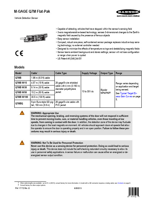
Vehicle Detection Sensor•Capable of detecting vehicles that have stopped within the sensor's sensing field•3-axis magnetoresistive-based technology; senses 3-dimensional changes to the Earth’smagnetic field caused by the presence of ferrous objects•Easy sensor installation•Compact, robust one-piece, self-contained sensor package replaces inductive-loop sens-ing technology; no external controller needed•Designed to minimize the effects of temperature swings and destabilizing magnetic fields•Sensor learns ambient background and stores settings; sensor will not lose configurationor range when power is cycled•US Patent # 6,546,344 B1ModelsWARNING: Appropriate UseThe mechanical opening, braking, and reversing systems of the door will not respond in sufficienttime to prevent moving trucks, cars, or material handling vehicles, even those traveling at lowspeeds, from coming in contact with the door. In addition, the detection zone of the device may fluctuatedue to changes in the local magnetic environment. All vehicles should approach doors at speeds that allowthe operator to ensure the door is operating properly and in an open position. Failure to follow these pro-cedures may result in serious injury or death.WARNING: Not To Be Used for Personnel ProtectionNever use this device as a sensing device for personnel protection. Doing so could lead to seriousinjury or death. This device does not include the self-checking redundant circuitry necessary to allow itsuse in personnel safety applications. A sensor failure or malfunction can cause either an energized or de-energized sensor output condition.Cordsets on page 8.M-GAGE Q7M Flat-PakP/N 117172 Rev. E8/26/2013OverviewThe M-GAGE Q7M Flat-Pak sensors implement a passive sensing technology to detect large ferrous objects. The sensor measures the change in the Earth’s natural magnetic field (the ambient magnetic field) caused by the introduction of a ferromagnetic object.The M-GAGE Q7M Flat-Pak sensors provide an alternative to inductive loop systems.Mount the Q7M sensor above-ground (see Installation on page 3).Theory of OperationThe sensor uses three mutually perpendicular magnetoresistive transducers.Each transducer detects magnetic field changes along one axis. By incorporat-ing three sensing elements, maximum sensor sensitivity is achieved.A ferrous object will alter the local (ambient) magnetic field surrounding the ob-ject, as shown in Figure 1. on page 2 and Figure 2. on page 2. The mag-nitude of this magnetic field change is dependent both on the object (size,shape, orientation, and composition) and on the ambient magnetic field (strength and orientation).During a simple programming procedure, the Q7M sensor measures the ambi-ent magnetic field. When a large ferrous object (for example, a truck, automo-bile, or rail car) alters that magnetic field, the sensor detects the magnetic field changes (anomalies). When the degree of magnetic field change reaches the sensor’s threshold, the sensor’s discrete outputs switch.Sensor Field of View and RangeThe sensor range depends on three variables:1.The local magnetic environment (including nearby ferrous material)2.The magnetic properties of the object to be sensed3.Sensor settingsThe Q7M sensor can detect changes in the ambient magnetic field in all direc-tions. As with other sensors, the range will depend on the target. The strong disturbance of a large ferrous object decreases as the distance from the sensor increases, and the magnitude and shape of the disturbance is dependent on the object’s shape and content.The sensor can be programmed to react to magnetic field disturbances of great-er or lesser intensity using two adjustments: background condition and sensitivi-ty level.Once background condition and sensitivity level are set, the sensor is ready todetect the target object. Both settings are stored in non-volatile memory.NOTE: The Q7M sensor will continue to sense a vehicle in its sensing field, even when the vehicleis stopped.ces caused by permanent ferrous-metal objectswithin or near the sensor.Figure 2.B. After a large steel target object is introduced,the sensor detects the differential (magnetic strength and orientation) between fields A and B.If the differential is greater than the sensitivity threshold, the sensor’s outputs conduct.M-GAGE Q7M Flat-PakTip: Sensor may be mounted inside a non-ferrous architectural detail for cosmetic or security reasons. It is important that, wherever it is mounted, the sensor is securely attached during configuration and all later use.If the sensor moves after being taught, detection errors may occur and sensor must be re-taught. If a sensor appears to lose its taught settings, it may be a result of having shifted position after setup.InstallationThe M-GAGE Q7M Flat-Pak is non-directional, and can be mounted in any position. The sen-sor may be mounted inside a non-ferrous architectural detail for cosmetic or security reasons.The end caps provide mounting holes at either end of the sensor. The sensor can be mounted to any desired surface (for example, cement or metal). Select a location as close as possible to the vehicle(s) to be detected.In applications where the sensor is mounted to the side of the vehicle traffic lane (for example,in a kiosk, menu board, or gate control box), consideration must be made for movement of metallic objects within a few feet of the sensor on the opposite side of the traffic lane, even if the activity is not visible (for example, behind a wall or inside a building). Consult Banner Ap-plications Engineer for further information.When mounting a QD-cable model, it is recommended to route the cable through conduit forprotection from environmental conditions. The integral cable does not need such protection.Figure 3. Installation using the mounting holes in the sensor'send capsMake sure that the sensor is securely attached during configuration and operation. If the sensor moves after being taught, detection errors may occur and the sensor must be re-taught. If a sensor appears to lose its taught settings, it may be a result of having shifted position after setup.Install the Sensor Above GroundRestriction: The models listed in this datasheet are not intended to be installed below ground due to inher-ent installation and environmental variability. Contact Banner Engineering for models designed for below ground installations.Installation Placement ConsiderationsFigure 4. Example good sensor placementGood PlacementFigure 4. Example good sensor placement on page 3shows an example of appropriate M-GAGE sensor placement for vehicle detection. The sensor is placed at the edge of a traffic lane to detect the vehicle in the near lane. This type of placement is often used for a kiosk,menu board, or gate control box.M-GAGE Q7M Flat-PakFigure 5. Example bad sensor placementBad PlacementFigure 5. Example bad sensor placement on page 4 de-picts a potential problem installation. While mounting the sensor at the side of a lane may be successful, this mounting location increases the potential for detection problems. To reliably detect a vehicle from the side, the sensor sensitivity must be increased in order to see ob-jects further away in the lane of interest. Unfortunately,this enables the sensor to also detect another object op-erating behind the sensor or vehicles in adjacent lanes,which will cause false counts.Place the M-GAGE sensor at the edge of a traffic lane only if there is no possibility of other objects being de-tected by the sensor. A good practice is to ensure that no vehicles will be within 3.05 m (10 ft) of the sensor on the non-traffic side.Sensor ConfigurationThe sensor is configured via its gray Remote wire. The gray wire is always active and the sensor may be re-configured at any time. For optimum performance, secure the sensor so that it will not move either during or following the configuration.Programming pulses may be executed by connecting the sensor's gray wire to the sensor's blue (common) wire with a normally open mechanical button connected between them, or as a low (< 2V dc) signal from a programmable logic controller (PLC), or using the model DPB1 Portable Programming Box, as shown in Figure 7. Connecting to the model DPB1 Portable Programming Box on page 4. When a PLC is used for configuration, the pulses are acknowledged via the sensor output signal.When the DPB1 is used, the pulses are accomplished by clicking the DPB1 TEACHpush button (0.04 seconds ≤ click ≤ 0.8 seconds).The sensor's output status is reflected by the DPB1 Output indicator LED.Configuration/Output ON LED Yellow)Power ON LED(Green)Figure 6. Sensor FeaturesFigure 7. Connecting to the model DPB1 Portable Programming BoxBrown Blue Gray White or BlackPush "TEACH" button to pulse the remote wire.M-GAGE Q7M Flat-PakConfigurationSet Background Condition (No Vehicle Present)Wire the M-GAGE ™ sensor as directed. Remove all vehicles and all other metal objects that are temporarily in the sensing area before setting the background condition.Set Sensitivity LevelLevel 1 = least sensitive, Level 6 = most sensitive.Typical Target Excess Gain CurvesAfter the sensor has been securely mounted and configured, it is ready to operate. The fol-lowing example application shows typical responses for the M-GAGE ™ sensor.Figure 8. Application example: sensor mounted 1 meter (3.3 ft) above ground on page 6describes mounting the M-GAGE ™ 1 meter (3.3 ft) above the ground to sense an automo-bile. The graph shows the excess gain for a typical car. Excess gain is a measure of the amount of extra signal detected by the sensor over and above the Level needed to detect the target. This example assumes a Level 5 sensitivity threshold.Excess Gain vs Sensitivity Level(Assumes Level 53)M-GAGE Q7M Flat-PakThe table at right compares the change in excess gain if the sensitivity Level changes. If the sensitivity is at Level 6, then the excess gain at a given distance would be 1.3 times larger than for a Level 5 sensitivity. Conversely, if the sensitivity threshold is Level 1, then the ex-cess gain would be one third as big as for Level 5.M-GAGEis not a factor.Distance from Vehicle SideE x c e s s G a i n (S e n s i t i v i t y L e v e l )012345678Figure 8. Application example: sensor mounted 1 meter (3.3 ft) above groundSpecificationsSupply Voltage10 to 30V dc (10% max. ripple) at 43 mA, exclusive of loadAbove +50° C (+122° F), supply voltage is 10 to 24V dc (10% max. ripple)Sensing RangeSee Figure 8. Application example: sensor mounted 1meter (3.3 ft) above ground on page 6Sensing TechnologyPassive 3-axis magnetoresistive transducer Supply Protection CircuitryProtected against reverse polarity and transient voltag-esOutput ConfigurationTwo SPST solid-state outputs conduct when object is sensed; one NPN (current sinking) and one PNP (cur-rent sourcing)Output ProtectionProtected against short-circuit conditionsAdjustmentsConfiguration of Background Condition and Sensitivity Level may be set by pulsing the gray wire remotely via the portable programming box (see Configuration on page 5)IndicatorsTwo indicators (see Figure 6. Sensor Features on page 4)Power Indicator: GreenConfiguration/Output Indicator: Red/Yellow Remote TEACH InputImpedance 12K ohms (low = < 2V dc)ConstructionLightpipes: AcrylicHousing: Anodized aluminumEnd Caps: Thermoplastic polyester Operating Conditions−40 °C to +70 °C (−40 °F to +158 °F)100% maximum relative humidity ConnectionsShielded 5-conductor (with drain) polyethylene jack-eted attached cable or 5-pin Euro-style quick-discon-nect PVC pigtail (see Cordsets on page 8)Environmental RatingLeak proof design is rated IEC IP69K; NEMA 6PM-GAGE Q7M Flat-PakOutput Ratings100 mA maximum (each output)NPN saturation: < 200 mV at 10 mA and < 600 mV at 100 mANPN OFF-state leakage current: < 200 microamps PNP saturation: < 1.2V at 10 mA and < 1.6V at 100 mAPNP OFF-state leakage current: < 5 microamps Output Response Time20 millisecondsDelay at Power-Up0.5 secondsTemperature Effect< 0.5 milligauss / ºC Vibration and Mechanical ShockAll models meet Mil. Std. 202F requirements method 201A (vibration: 10 to 60Hz max., double amplitude0.06 in, maximum acceleration 10G). Also meets IEC947-5-2: 30G 11 ms duration, half sine wave. PatentU.S. Patent 6,546,344 B1CertificationsDimensions7.5 mm (0.30")19 mm(0.75")10.0 mm(0.39")CableorQD PigtailMaximum AllowableTorque: 7 in - lbs Hookups+10 - 30V dc–+10 - 30V dc–1 = Brown2 = White3 = Blue4 = Black5 = Gray AccessoriesM-GAGE Q7M Flat-PakM-GAGE Q7M Flat-PakCordsetsBanner Engineering Corp Limited WarrantyBanner Engineering Corp. warrants its products to be free from defects in material and workmanship for one year following the date of shipment. Banner Engineering Corp. will repair or replace, free of charge, any product of its manufacture which, at the time it is returned to the factory, is found to have been defective during the warranty period. This warranty does not cover damage or liability for misuse, abuse, or the improper application or installation of the Banner product.THIS LIMITED WARRANTY IS EXCLUSIVE AND IN LIEU OF ALL OTHER WARRANTIES WHETHER EXPRESS OR IMPLIED (IN-CLUDING, WITHOUT LIMITATION, ANY WARRANTY OF MERCHANTABILITY OR FITNESS FOR A PARTICULAR PURPOSE), AND WHETHER ARISING UNDER COURSE OF PERFORMANCE, COURSE OF DEALING OR TRADE USAGE.This Warranty is exclusive and limited to repair or, at the discretion of Banner Engineering Corp., replacement. IN NO EVENT SHALL BANNER ENGINEERING CORP. BE LIABLE TO BUYER OR ANY OTHER PERSON OR ENTITY FOR ANY EXTRA COSTS, EXPEN-SES, LOSSES, LOSS OF PROFITS, OR ANY INCIDENTAL, CONSEQUENTIAL OR SPECIAL DAMAGES RESULTING FROM ANY PRODUCT DEFECT OR FROM THE USE OR INABILITY TO USE THE PRODUCT, WHETHER ARISING IN CONTRACT OR WAR-RANTY, STATUTE, TORT, STRICT LIABILITY, NEGLIGENCE, OR OTHERWISE.Banner Engineering Corp. reserves the right to change, modify or improve the design of the product without assuming any obligations or liabilities relating to any product previously manufactured by Banner Engineering Corp.。
车辆检测卡使用手册.
车辆检测卡使用手册
车辆检测卡使用手册
1 页共 8 页
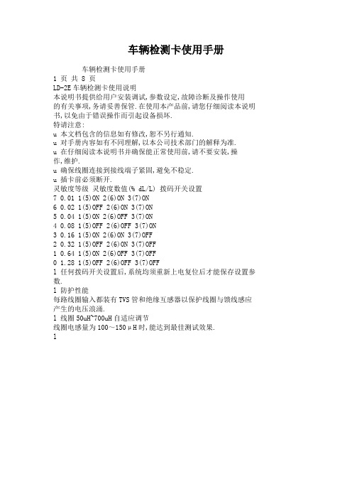
LD-2E车辆检测卡使用说明
本说明书提供给用户安装调试,参数设定,故障诊断及操作使用
的有关事项,务请妥善保管.在使用本产品前,请您仔细阅读本说明书,以免由于错误操作而引起设备损坏.
特请注意:
u 本文档包含的信息如有修改,恕不另行通知.
u 对手册内容如有不同理解,以本公司技术部门的解释为准.
u 在仔细阅读本说明书并确保能正常使用前,请不要安装,操
作,维护.
u 确保线圈连接到接线端子紧固,避免不稳定.
u 插卡前必须断开.
灵敏度等级灵敏度数值(% dL/L) 拨码开关设置
7 0.01 1(5)ON 2(6)ON 3(7)ON
6 0.02 1(5)OFF 2(6)ON 3(7)ON
5 0.04 1(5)ON 2(6)OFF 3(7)ON
4 0.08 1(5)OFF 2(6)OFF 3(7)ON
3 0.16 1(5)ON 2(6)ON 3(7)OFF
2 0.32 1(5)OFF 2(6)ON 3(7)OFF
1 0.64 1(5)ON 2(6)OFF 3(7)OFF
0 1.28 1(5)OFF 2(6)OFF 3(7)OFF
l 任何拨码开关设置后,系统均须重新上电复位后才能保存设置参数.
l 防护性能
每路线圈输入都装有TVS管和绝缘互感器以保护线圈与馈线感应产生的电压浪涌.
l 线圈50uH~700uH自适应调节
线圈电感量为100~150μH时,能达到最佳测试效果.
l。
TLD-110中性车辆检测器说明书(中英文)

线圈型车辆检测器使用说明NO:9001- 0110-232■ 安装检测器 ■ 接线图车辆检测器必须安装在离检测线圈尽可能近的防水、防潮的干燥环境里。
安装位置必须选择在远离热源、强磁场的地方,其四周应与其它装置保持至少10毫米的距离(请勿紧贴机箱安装)。
检测器能否良好工作在很大程度上取决于它所连接的检测地感线圈。
埋设线圈的几个重要参数包括:环境(回避高温、强磁、可移动金属等)、材料、线圈形状大小、匝数、埋设方法(参见《线圈安装指南》)。
■ 使用及工作指示接通电源后,检测器将会自动校准。
校准过程约3秒。
校准进行时,面板上的LED 会闪烁(亮0.5秒,灭0.5秒)几次。
在校准期间,不应有车停在线圈上。
当校准成功后,面板上的“检测”指示灯熄灭,当线圈上有车通过时,面板上的“检测”指示灯亮起,且存在输出继电器2(3、4脚)吸合导通;若在校准过程中未检测到线圈或线圈电感值不在允许范围内,对应的LED 指示灯会不停地闪烁。
其闪烁情况如下:线圈未连接: 线圈电感太小: 线圈电感太大:■ 工作频率调节本产品提供两种频率选择,用户可以更改线圈的工作频率以避免相邻线圈或环境频率的干扰。
先取下检测器顶端的黑色面盖,拔动主板上的拔码开关DIP5即可调整工作频率。
DIP5拔至ON 时为低频,DIP5拔至OFF 时为高频。
■ 灵敏度调节灵敏度调节使用面板上的滑动开关,有三档:H 为高灵敏度,M 为中灵敏度,L 为低灵敏度。
在试运行时,先将灵敏度设在较低档位,在实际测试后如果车辆检测没有反应,则应将灵敏度调高一档,如此反复,直至车检器稳定、正常工作。
[注意]:如果线圈不能正常工作,应首先检查线圈埋设情况(连接线是否双绞、破损等);然后再调整工作频率或灵敏度级别。
■ 继电器输出方式继电器2(3、4、11脚)输出方式由拔码开关DIP3决定:当DIP3拔至OFF 时为存在输出,即如有车辆进入线圈时,3、4脚吸合导通,直至车辆离开线圈;当DIP3拔至ON 时,继电器2的输出与继电器1的输出方式相同(由DIP1和DIP2决定)。
TLD500-600车辆检测器技术手册 V2.1

TLD-500/600系列车辆检测器技术手册版本 2.11. 简介德立达智能车辆检测器用于检测车辆等金属物,适用于停车场系统、公路车辆收费站以及信号灯控制系统等。
其中TLD-600为双通道型,TLD-500为单通道型。
2. 技术参数﹡型号:TLD-600(双通道)TLD-500(单通道)﹡工作温度:-20~ +55℃﹡储存温度:-40~ +70℃﹡相对湿度:≤95%、无凝露﹡外壳:PC+ABS工程塑料﹡安装:DIN导轨﹡尺寸:100*70*118mm﹡重量:400g﹡工作电压:220V AC ±10%﹡额定功率:<5W﹡继电器输出:DC24V/3A﹡工作频率:20~170 KHz﹡反应时间:10毫秒﹡灵敏度:0~9级﹡线圈电感量:50~1000 uH(推荐100~300 uH)﹡线圈连接线:推荐小于5米,每米绞合20次以上,总电阻小于10欧姆﹡自动校准时间:2~5秒3.工作原理车辆检测器就是通过探测金属物在感应线圈上电感量的变化来探测到金属物的。
线圈是由多匝导线绕制的,埋在路面下,用水泥填充好,引线连至检测器。
当金属物通过感应线圈时,线圈的电感量发生了一些变化,这个变化被检测器检测到,通过内部智能控制器的运算判断出有金属物,并通过输出继电器输出信号。
由于有微处理器的智能控制作用,检测器的灵敏度可以适应各种要求,对不同大小的感应线圈和引线均能良好匹配。
双通道车辆检测器TLD-600面板接线图单通道车辆检测器TLD-500面板接线图a. 线圈调谐车辆检测器的调谐过程是完全自动的。
当检测器加电或复位时,将自动调谐到它所接的线圈,调谐范围为50到1000微亨。
这样宽的调谐范围保证了对线圈和引线很低的要求。
一旦调谐好,任何环境对电感量缓慢变化都将反馈到探测器内部的补偿电路,保证正常工作。
b. 灵敏度调节车辆检测器的灵敏度取决于以下因素:线圈大小,线圈匝数,引线长度、线圈下方是否有金属。
检测器的灵敏度是为停车场系统特别优化的,当选择较低值时,会对底盘较高或带拖车的车辆有很好的反应,而自行车、手推车等较小的金属物则不会引起探测器动作。
DMG 100-110数字多功能测量器说明书
Digitalmultimeters DMG 100-110Digital multimeters are capable of viewing measurements with high accuracyon the wide LCD display which allow to control energy distribution networks.Easy and intuitive menu navigationLCD display with text in 6 languagesHigh measurement accuracyDisplay of voltage and current harmonics up to the 15th orderWide range for power supply, measurements and temperatureSuitable for LV, MV and HV electric systems and installationsDMG 100 - 110Voltage: phase, line and phase to neutral Phase current (calculated neutral current)Power: apparent, active, reactive per phase and totalPhase and total power factor FrequencyMaximum, average and minimum values for all measurementsMaximum power and current demand Voltage and current asymmetryVoltage and current harmonics up to the 15th orderTotal harmonic distortion (THD) of voltages and currentsPartial and total active, reactive andapparent energy meters (phase and system)Programmable partial and total hour countersPhase active power unbalance.The main features include an intuitive and easy-to-read LCD interface, excellent measurement accuracy (±0.5% for voltages and currents) and extended power supply compatibility (100...240VAC).Main measurements and functions include: Unit of measureMeasured valueIntegrated opto-isolated RS485 serial port (DMG 110 only)Type of measurementSubpage indicationInstantaneous, maximum, minimum, average values and maximum demandBar graphScrolling text for alarms,user messages,parameter settings and active energy measurementsDMG 100 - 110Maximum power demand managementUtility-user contracts often stipulate a limit for maximum power demand, calculated as anaverage over a time window. DMG100 and DMG110 multimeters include functions thatallow users to control demand limits:•A limit threshold can be set for average power demand.•The devices provide 4 methods for calculating average power demand to suit differentoperating requirements:- Fixed window- Mobile window- Synchronisation by serial bus (Modbus) message.LCD displayBacklit icon display for good visibility even in poor lighting.Scrolling text:• Alarm messages configured by the user• Help messages for the user• Description of setup menu and parametersText is available in 6 languages: English, Italian, French,Portuguese, Spanish and German.Alarms and messages with flashing displayFour user-programmable alarms with descriptive text can be configured for each limit threshold.When an alarm is triggered, a programmable message is displayed on a dedicated page. A dedicated parameteris provided for users to select flashing of the display backlight in case of alarms. This makes alarm conditionseasier to see even from a distance.HOW TO ORDERSTechnical specifications– Auxiliary power supply:100...240VAC / 115...250VDC– Voltage measurement range: 50...720VAC– Suitable for use in medium voltage systems withvoltage transformer– Rated input current: 1A or 5A– Frequency measurement range: 45...66Hz– TRMS voltage and current measurements– Measurement accuracy:•Voltage: ±0.5% (50...720VAC)•Current: ±0.5% (0.1...1.1 In)•Power: ±1% f.s.•Frequency: ±0.05%•Active energy: Class 1 (IEC/EN 62053-21)•Reactive energy: Class 2 (IEC/EN 62053-23)– Display of voltage and current harmonics up tothe 15th order– Modbus-RTU, ASCII communication protocol–Compatible with and software(DMG 110 only)– Modular 4U housing– IEC protection rating: IP40 on front;IP20 at terminals.Certifications and complianceCertifications obtained: EAC, cULus (bothpending).Comply with standards: IEC/EN 61010-1,IEC/EN 61000-6-2, IEC/EN 61000-6-3,UL 61010-1, CSA C22-2 n°61010-1.DMG 100 - DMG 110Code DescriptionDMG 100 Modular 4U multimeter with backlit LCD icon display, auxiliary power supply100...240VAC / 115...250VDCDMG 110 Modular 4U multimeter with backlit LCD icon display, auxiliary power supply100...240VAC / 115...250VDC, with integrated RS485 serial portenergy management softwareto supervise and control (via Web server) the electricalparameters measured by LOVATO Electric deviceswith a communication port.In addition to providing datalogs and simple,user-configured Web pages, it can also be used to:•Configure alarms (for sending by email)•Make and view trend graphs•Send commands to devices•Energy usage by time slots.configuration and remote control softwareprovides for:•Transfer parameter settings from PC to DMG 110and vice-versa•Read measurements•Display events and alarms•Send commands.T h e p r o d u c t s d e s c r i b e d i n t h i s p u b l i c a t i o n a r e s u b j e c t t o b e r e v i s e d o r i m p r o v e d a t a n y m o m e n t . C a t a l o g u e d e s c r i p t i o n s a n d d e t a i l s , s u c h a s t e c h n i c a l a n d o p e r a t i o n a l d a t a , d r a w i n g s , d i a g r a m s a n d i n s t r u c t i o n s , e t c ., d o n o t h a v e a n y c o n t r a c t u a l v a l u e . I n a d d i t i o n , p r o d u c t s s h o u l d b e i n s t a l l e d a n d u s e d b y q u a l i f i e d p e r s o n n e l a n d i n c o m p l i a n c e w i t h t h e r e g u l a t i o n s i n f o r c e f o r e l e c t r i c a l s y s t e m s i n o r d e r t o a v o i d d a m a g e s a n d s a f e t y h a z a r d s .P D 101 G B 04 15Follow uswww.L ovato E LOVATO ELECTRIC S.P .A.VIA DON E. MAZZA, 1224020 GORLE (BERGAMO) ITALYLOVATO Electric offices in the worldLOVATO Electric products are available in over 100 countries through its distributors.Sales Department:Tel.+39 035 4282354Fax +39 035 4282400Tel +39 035 4282111Fax +39 035 4282200E-mail info@L ovato E United Kingdom LOVATO ELECTRIC LTD Tel. +44 8458 Czech RepublicLOVATO ELECTRIC S.R.O.Tel. +420 226 203203www.LovatoElectric.czGermany LOVATO ELECTRIC GmbH Tel. +49 7243 7669370www.LovatoElectric.deUSALOVATO ELECTRIC INC.Tel. +1 757 Spain LOVATO ELECTRIC S.L.U.Tel. +34 93 7812016www.LovatoElectric.esCanadaLOVATO ELECTRIC CORP .Tel. +1 450 6819200www.Lovato.caPoland LOVATO ELECTRIC SP . Z O.O.Tel. +48 71 7979010www.LovatoElectric.plUnited Arab EmiratesLOVATO ELECTRIC ME FZE Tel. +971 4 3712713www.LovatoElectric.aeRomaniaLOVATO ELECTRIC SRL Tel. +40 372 074 155www.LovatoElectric.roTurkey LOVATO ELEKTR K LTD Tel. +90 216 .trChinaLOVATO ELECTRIC (SHANGHAI) CO LTD Tel. +86 21 。
TLD-110车辆检测器技术手册V2.00

TLD-110车辆检测器技术手册V2.00版本2.001. 简介TLD-110型智能车辆检测器,主要用于车辆存在检测。
适用于停车场、公路车辆收费站以及交通信号灯控制等系统。
TLD-110为单通道型,它只能联接一个电感线圈,但有两个输出继电器可提供两组输出信号;TLD-110分别提供不同的输出信号供用户选择。
2. 技术参数AC/DC12V 可选择,2.5W功率频率范围:20KHz―170KHz灵敏度:三级可调反应时间:100毫秒环境补偿:自动飘移补偿线圈电感:推荐150uH―300uH(包含连接线)最大50uH―500uH(包含连接线)工作电源:AC220V、AC110V、AC/DC24V、连线长度:推荐小于20米,每米绞合20次以上,总电阻小于10欧姆储存温度:-40C到+85C工作温度:-20C到+65C相对湿度:≤95%(无凝露)外形尺寸:113*74*37mm(含底座)三、使用方法3.1 检测器的安装车辆检测器必须安装在离探测线圈尽可能近的、防水防潮的干燥环境里。
在安装车辆检测器时,应与其它设备或装置保持一定的距离(约10―20mm)以方便维护。
检测器能否良好工作在很大程度上取决于它所连接的感应线圈。
线圈的几个重要参数包括:线圈材料,线圈形状和是否正确施工埋设。
关于线圈的安装请参阅后续章节的“线圈安装指南”。
3.2 车辆检测器接线示意图图一、TLD-110接线端子接线示意图3.3 工作频率设定线圈频率调整用设置在电路板上的两个DIP开关进行。
如进行调整,必须先关闭电源再将检测器从插座上取下并拆开胶壳。
DIP开关6(LA)用于设置频率;开关在“ON”位置时表示低频工作方式,在“OFF”位置表示高频工作方式。
在频率调整后,检测器会在重新上电复位时自动进行标定。
注意:TLD-110在出厂时已设为高频。
当两个检测器的安装距离较近时,用户可以将两个检测器设置成不同的频率。
3.4 灵敏度调整TLD-110车辆检测器检测灵敏度共分为三级,可通过顶端面板(见图二)上的三位滑动拔码开关来设定:“H”位置为最高灵敏度;“M”位置为中级灵敏度;“L”位置为最低灵敏度。
机动车检测站质量手册-计量认证范围及限制要求

不测并装轴车辆的整备质量,制动检验适用于滚筒式制动检验台
7
汽车车速表
7.1
车速表指示误差
8
汽车轮重及整车质量
8.1
轮重/轴重
8.2
整车质量
9
汽车制动性能(台试)
9.1
空载制动率
9.2
空载制动不平衡率
9.3
整车制动率
1项),外廓尺寸测量适用于附录A,不适于自动测量
、2
车辆特征参数检查
2.1
附录H表H.1共10项
3
车辆外观检查
3.1
附录H表H.1共6项
4
安全装置检查
4.1
附录H表H.1共20项
5
底盘动态检验
6.1
附录H表H.1共4项
6
车辆底盘部件检查
7.1
附录H表H.1共5项
6
汽车传向轮横七计量认证范围及限制要求(共2页 第1页)
序号
检测产品/类别
检测项目/参数
检测标准(方法)名称及
编号(含年号)
限制范围或说明
序号
名称
1
车辆唯一性检查
1.1
附录H表H.1共5项
GB7258-2012《机动车运行安全技术条件》
GB21861-2014《机动车安
全技术检验项目与方法》
、
适用于GB21861-2014附录H.1(共5
2个检测工位适用于稳态工况法测量和双怠速法,底盘测功机最大吸收功率160KW
12.2
CO含量
12.3
NO含量
12.4
λ值
13
- 1、下载文档前请自行甄别文档内容的完整性,平台不提供额外的编辑、内容补充、找答案等附加服务。
- 2、"仅部分预览"的文档,不可在线预览部分如存在完整性等问题,可反馈申请退款(可完整预览的文档不适用该条件!)。
- 3、如文档侵犯您的权益,请联系客服反馈,我们会尽快为您处理(人工客服工作时间:9:00-18:30)。
TLD-100/110系列车辆检测器
技术手册
版本 2.00
TLD-100/110型智能车辆检测器,主要用于车辆存在检测。
适用于停车场、公路车辆收费站以及交通信号灯控制等系统。
TLD-100和TLD-110系列均为单通道型,它只能联接一个电感线圈,但有两个输出继电器可提供两组输出信号;TLD-100和TLD-110系列分别提供不同的输出信号供用户选择。
工作电源:AC220V、AC110V、AC/DC24V、
AC/DC12V 可选择,2.5W功率
频率范围:20KHz—170KHz
灵敏度:三级可调
反应时间:100毫秒
环境补偿:自动飘移补偿
线圈电感:推荐80uH—300uH(包含连接线)
最大50uH—500uH(包含连接线) 连线长度:最长5米,每米至少绞合20次,总
电阻小于10欧姆。
储存温度:-40ºC到+85ºC
工作温度:-40ºC到+65ºC
相对湿度:最大95%
外形尺寸:85×74×36mm
3.1 检测器的安装
车辆检测器必须安装在离探测线圈尽可能近的、防水防潮的干燥环境里。
在安装车辆检测器时,应与其它设备或装置保持一定的距离(约10—20mm)以方便维护。
检测器能否良好工作在很大程度上取决于它所连接的感应线圈。
线圈的几个重要参数包括:线圈材料,线圈形状和是否正确施工埋设。
关于线圈的安装请参阅后续章节的“线圈安装指南”。
3.2 车辆检测器接线示意图
图一、TLD-100/110接线端子接线示意图
3.3 工作频率设定
线圈频率调整用设置在电路板上的两个DIP开关进行。
如进行调整,必须先关闭电源再将检测器从插座上取下并拆开胶壳。
DIP开关6(LA)用于设置频率;开关在“ON”位置时表示低频工作方式,在“OFF”位置表示高频工作方式。
在频率调整后,检测器会在重新上电复位时自动进行标定。
注意:TLD-100和TLD-110在出厂时已设为高频。
当两个检测器的安装距离较近时,用户可以将两个检测器设置成不同的频率。
灵敏度调整
TLD-100/110车辆检测器检测灵敏度共分为三级,可通过顶端面板(见图二)上的三位滑动拔码开关来设定:
“H”位置为最高灵敏度;
“M”位置为中级灵敏度;
“L”位置为最低灵敏度。
圈二、灵敏度开关
3.5 系统复位及工作调试
注意:当检测器上电复位时应确保线圈上没有车辆或其它金属物体。
、当检测器加电后,它会自动检测并调谐到所连接的线圈。
这一过程约有5秒钟左右,同时顶部面板上的LED会闪烁(亮0.5秒,灭0.5秒)几次。
2)、检测器在调谐过程将对线圈进行测试,当线圈的电感量超出允许范围或是发生断路、短路现象,LED将连续闪亮。
如果线圈测试正常,则顶部面板上的LED熄灭不再闪烁,并进入正常工作状态(此时,继电器不吸合)。
3)、检测器在检测到有车辆到来时,会吸合标准输出相对应的继电器,同时点亮对应的LED指示灯;当车辆离开时,将释放标准输出相对应的继电器,同时熄灭对应的LED指示灯。
4)、如果检测器在线圈有感应时没有反应,应重新调整灵敏度。
3.6 错误指示
当检测器上电自检时,如果检测到线圈未连接或线圈电感值不在允许范围内,对应的LED指示灯会不停地闪烁。
其闪烁情况如下:
3.7 继电器输出
检测器能否良好工作在很大程度上取决于它所连接的感应线圈。
线圈的几个重要参数包括:线圈材料,线圈形状和是否正确施工埋设。
在安装时必须注意以下事项:
4.1 线圈串扰
当两个感应线圈靠得很近,两个线圈的磁场迭加在一起,相互造成干扰。
这种现象就是串扰。
串扰会导致错误的检测结果和环路检测器的死锁。
在相邻的但属于不同感应器的线圈间,要消除串扰,可以采取以下措施:
●选择不同的工作频率。
●将相邻的线圈间距加大。
必须保证探测线圈
之间的间距大于2米;
●对线圈引出导线进行良好的屏蔽,屏蔽线必
须在探测器端接地。
线圈电缆和接头最好采
用多股铜导线。
在电缆和接头之间最好不要
有接线处。
如果必须有接线端,也要保证连
接可靠,用烙铁将它们焊接起来,并且放置
于防水处。
导线截面积不小于1.5平方毫米。
4.2 线圈形状及匝数
除非条件不允许,探测线圈应该是长方形。
两条长边与车辆(金属物)运动方向垂直,彼此间距推荐为1米。
长边的长度取决于道路的宽度,通常两端比道路宽度窄0.3米。
线圈周长如果超过10米,需要绕两匝。
周长如果在10米以内,需要绕三匝或更多。
周长在6米以内,要绕四匝或五匝。
安装时的一个好方法是把相邻的线圈交替三匝和四匝。
4.3 线圈安装要领
线圈埋设首先要用切路机在路面上切出槽来。
在四个角上进行45度倒角,防止尖角破坏线圈电缆。
切槽宽度一般为4毫米,深度30到50毫米。
同时还要为线圈引线切一条通到路边的槽。
具体如图一所示:
图一、线圈安装示意图
在埋设电缆时,要留出足够的长度以便连接到环路感应器,又能保证中间没有接头。
绕好线圈电缆以后,将电缆通过引出线槽引出。
输出引线是紧密双绞的形式,最少1米绞合20次。
引线最大长度不应超过5米。
由于探测线圈的灵敏度随引线长度的增加而降低,所以引线电缆的长度要尽可能短。
埋好线圈以后,用水泥或沥青封上。
- 10 -。