德国罗曼M2智能型掌上涡流仪
第三节涡流检测的

涡流探伤仪,分选,扫描成像, 涡流探伤仪,分选,扫描成像,磁记忆应力诊断
Hale Waihona Puke 钢管涡流检测脉冲涡流检测技术研究及其应用的新进展
2 脉冲涡流检测的基本原理
图1 脉冲涡流的产生及检测信号的拾取过程
表3-1 涡流检测的应用
检测目的 探 伤
影响涡流特性的因素
缺陷的形状、 缺陷的形状、尺寸和位置 电导率 检测距离和薄板长度 工件的尺寸和形状
用
途
导电的管、棒、线材及零部件 导电的管、 的缺陷检测 材料分选和非磁性材料电导率 的测定 覆膜和薄板厚度的测量 工件尺寸和形状的控制
3、结构件疲劳裂纹探伤 服役中的结构件上可能产生各种缺陷, 服役中的结构件上可能产生各种缺陷 , 尤以疲劳裂纹为 多见。适合采用探头式线圈进行检测的,既包括形状复杂的零 多见。适合采用探头式线圈进行检测的 也包括除管、 棒材以外形状不规则的材料和零件, 件, 也包括除管、 棒材以外形状不规则的材料和零件,如板 材、 型材等。 型材等。 由于这类材料和零件的形状、 结构多种多样, 由于这类材料和零件的形状 、 结构多种多样 , 因此探头 式线圈的形貌也多种多样。 式线圈的形貌也多种多样。比如要采用涡流方法完成飞机维修 手册所规定的全部检查项目,就要配备以下各式探头, 手册所规定的全部检查项目,就要配备以下各式探头,包括笔 式探头、 钩式探头、 平探头、 孔探头和异形探头等。 式探头、 钩式探头、 平探头、 孔探头和异形探头等。
二、材质检验 材质检验 电导率的测量是利用涡流电导仪测量出非铁磁性金属的 电导率 的测量是利用涡流电导仪测量出非铁磁性金属的 电导率值,而电导率值与金属中所含杂质、材料的热处理状态 电导率值,而电导率值与金属中所含杂质、 以及某些材料的硬度、耐腐蚀等性能有关,所以可进行材质的 以及某些材料的硬度、耐腐蚀等性能有关,所以可进行材质的 分选。 分选。 材料的电导率是影响检测线圈阻抗的重要因素, 材料的电导率是影响检测线圈阻抗的重要因素 , 因此在 涡流检测中可用来评价材料的材质和其他性能。 涡流检测中可用来评价材料的材质和其他性能。这种评价不会 损伤零部件的加工表面,且特别适合现场检测。 损伤零部件的加工表面,且特别适合现场检测。
管道内检测——精选推荐

管道内检测管道作为现代五⼤运输⽅式(铁路、公路、航空、⽔运、管道)之⼀,在安全、便捷、经济等⽅⾯具有其他四种传统运输⽅式不可⽐拟的优势。
⽬前国内约99%天然⽓和70%的原油通过管道进⾏运输,因此管道也具有了“能源动脉”的称号。
既然是能源动脉,就和⼈的⾎管⼀样会发⽣类似于⾎栓、⾎管壁变薄、丧失弹性等危险。
图1:从管道中清理出的杂质对于由于杂质堆积、析蜡等造成的管道“⾎栓”,通常采取清管的⽅式予以清除“⾎栓”。
但是对于管道腐蚀、应⼒集中等造成的管道壁变薄、裂纹,⽬前世界上通⽤的做法是进⾏管道“内检测”。
管道内检测即是:在不影响输油运⾏的情况下,利⽤管道内运⾏的可实时采集并记录管道信息的检测器所完成的检测,也称智能清管。
管道内检测按照检测⽬的来分类有:⼏何检测、⾦属损失检测和裂纹检测,如果按照检测器⼯作原理来分类,就会有漏磁检测、超声波检测和涡流检测等。
⽬前国内管道上普遍进⾏的是⼏何检测和漏磁检测。
顾名思义,⼏何检测就是检测管道是否发⽣变形,漏磁检测则是利⽤磁化的钢制管道在⾮均质点会发⽣磁通量变化的原理来检测管道的⾦属损失点和“三通”等特征点。
⽬前最先进的漏磁内检测器为“三轴⾼清”漏磁检测器,在国内管道上也有⼤范围应⽤。
内检测器的照⽚如下:图2:⼏何变形检测器图3:超声检测器图4:超⾼清漏磁检测器下⾯以某成品油管道内检测⼯作为例对内检测流程进⾏介绍。
该成品油管道内检测⼯作有三个阶段:⼀是常规清管,通常使⽤软体清管器、⽪碗清管器、磁⼒清管器、测径清管器完成,⽬的是清除管内杂质、⽔及硫酸根还原菌(厌氧菌)等,减缓管道内腐蚀,降低管道阻⼒,初步评估⼏何检测器能否顺利通过。
⼆是⼏何检测,除上⾯说的检查管道存在变形和椭圆度,还有就是检测评估漏测检测器能否顺利通过。
三是“漏磁检测”,主要是查找管道⾦属损失缺陷、焊接缺陷、盗油阀等。
现场内检测⼯作完成后,进⼊以下⼯作流程:对海量数据进⾏分析;出具初步报告,查找重⼤缺陷;出具正式报告,开挖验证;管道缺陷评价,制定修复计划;制定修复⽅案,完成缺陷修复,消除管道本体隐患。
EMF Series Electromagnetic Flow Meters说明书
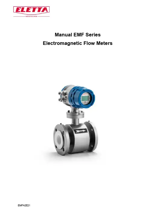
Manual EMF Series Electromagnetic Flow MetersContent Page 1. General Information 31.1. Product Description 31.2. Unpacking and Inspection 31.3. Transport and Handling 32. Technical Data 42.1. Measuring system 42.2. Design 42.3. Measuring Accuracy 42.4. Operating conditions 52.5. Installation conditions 52.6. Materials 53. Models and Selection 64. Cautions for Installation 74.1 Mounting Positions 74.2. Required Lengths of the Straight Runs 84.3 Grounding 84.4 Connections 95. Electrical Wiring 105.1. Safety Instructions 105.2 Terminal Configuration Diagram 105.2.1 Compact Converter Terminal Configuration 105.2.2. Remote Converter Terminal Configuration 116. Programming and Setup 116.1. Description of Outputs 116.1.1. Digital Frequency Output 116.1.2. Digital Pulse Output 126.1.3. Alarm Output 126.2. Output Connection 126.2.1. Current Output 126.2.2. Digital Voltage Output 136.2.3. Digital Voltage Output to Photoelectric Coupling 136.2.4. Digital Output to Relay 137. Operation and Setup 147.1. Display and Keys 147.1.1. Compact Version 147.1.2 Remote Type 147.2. Function Selection Menu 157.3. Parameters Setting 157.4. Parameter Function Table 178. Alarm Information 199. Troubleshooting 1910. Contact 201. General InformationThis manual will assist you in installing, using and maintaining the Eletta flow meter. lt is your responsibility to make sure that all operators have access to adequate instructions about safe operating and maintenance procedure.For your safety, review the major warnings and cautions below before using your equipment.Use only fluids that are compatible with the housing material and wetted components of your meter. When measuring flammable liquids, observe precautions against fire or explosion.When handling hazardous liquids, always follow the fluids manufacturer's safety precautions.When working in hazardous environments, always apply appropriate safety precautions.During meter removal, fluids may spill. Follow the fluids manufacturer's safety precautions for clean up of minor spills.When tightening the meter, use a wrench only on the wrench flats.For best results, calibrate the meter at least 1 time per year.1.1. Product DescriptionElectromagnetic flow meters are intended for fluid measurement in most industries including water, wastewater, food and beverage, pharmaceutical and chemical.The Eletta electromagnetic flow meter consists of two main components:1) The Detector, which includes the flow tube, isolating liner and measuring electrodes, and2) The Converter, which is the electronic device responsible for signal processing, flow calculation, display and output signals.The materials of construction of the wetted parts (liner and electrodes) should be appropriate for the specifications on the intended use. Review of the compatibilities of the specifications is recommended.Eletta's electromagnetic flow meters are factory tested and calibrated. A calibration certificate is included in the shipment of each meter.1.2. Unpacking and InspectionUpon receipt, check your meter for visible damage. The meter is a precision measuring instrument and has to be handled carefully. Remove the protective plugs and caps for a thorough inspection, If any items are damaged or missing, contact us.Make sure the flow meter model meets your specific needs. For your future reference, it might be useful to record this information on nameplate in the manual in case it becomes unreadable on the meter.1.3. Transport and HandlingDo not lift the detector from the Converter housing, the junction box or the connecting cable. The use of lifting lugs for larger sizes is recommended. Very large meter sizes are packed and crated with the meter laying on its side for shipping safety and stability reasons. In order to lift the meter in vertical position, it's recommended to use a sling rigged method as shown below.Warning: NEVER insert the forklift`s fork,chains, wire slings or any other sharp object inside the flow tube for lifting or handling purpose. This could permanently damage the isolating liner and could render the meter inoperable.lf using a forklift, do not lift the detector on its body between the flanges. The housing could be accidentally dented and permanent damage could be caused to the internal coil assemblies. 2. Technical Data2.1. Measuring system2.2. DesignFully welded maintenance-free sensorFlange version with full bore flow tubeLarge diameter range from DN25 -DN3000 with rugged liners approved for drinking water Industry specific insertion lengthsModular construction: The measurement system consists of a flow sensor and a signal converter. lt is available as compact and as remote version.Compact version power supply: 110-VAC Power, 18-36V DC Power, Battery PowerRemote version power supply: 110-240VAC Power, 18-36VDC Power, Battery Power Measurement range: -12 ... +12 m/s2.3. Measuring Accuracy2.4. Operating conditionsProcess temperature Hard rubber liner: -5 ... +60°CPolypropylene liner: -5 ... +90°CPTFE liner: -5 ... +120°CAmbient temperature -20 ... +60°C(Protect electronics against self-heating with ambient temperatures >55°C) Storage ternperature -20 ... +70°CPressure PN16Pressure drop negligibleFluid Physical condition: conductive liquidsElectrical conductivity 5 μSiemens/cmPermissible gas content (volume) <=5%Permissible solid content (volume) <=70%2.5. Installation conditionsTake care that the flow sensor is always fully filled.For detailed information see chapter 4. "Cautions for Installation".Flow direction forward and reverse. Arrow on flow sensor indicates positive flow direction.Inlet run 5DNOutlet run 2DN2.6. Materials (also see Chapter 3, Models and Selection)Sensor housing Sheet steel, Polyurethane coatedMeasuring tube Austenitic stainless steelFlanges Carbon steel; Polyurethane coatedOption: stainless steelLiner DN10-DN40: F46DN50-DN300: PTFE or Hard Rubber>DN300: Hard RubberConnection box (only remote versions): polyurethane coated die-cast aluminiumMeasuring electrodes: Standard: Stainless steel 316LOption: Hastelloy C, Titanium, TantalumGrounding rings Standard: Stainless steelGrounding electrodes (option) Same material as measuring electrodesMeasurable Flow RangeGenerally, the Flow Meter is calibrated between 0.3-6m/s if there is not special request3.Models and Selection4. Cautions for Installation4.1 Mounting PositionsPipes must be fully filled with liquids. It is essential that pipes remain fully filled at all times, otherwise flow rate indications may affected, and measurement errors may be caused.Avoid Air Bubbles. If air bubbles enter a measurement pipe, flow rate indications may be affected and measurement errors may be caused.If the electrodes are vertical to the ground, air bubbles near the top or precipitates at the bottom may cause measurement errors.. Ensure that the terminal box is mounted above the piping to prevent water from entering them.Avoid all pipe locations where the medium is pulsating, such as in the outlet side of piston or diaphragm pumps.Avoid locations near equipment producing electrical interference such as electric motors, transformers, variable frequency etc.Install the meter with enough room for future access for maintenance purposes.The magnetic meter isolating liner, whether if it is PTFE or rubber, ls not intended to be used as gasket material. Standard gaskets (not provided) should be installed to ensure a proper hydraulic sealing. When installing the gaskets, make sure they are properly centered to avoid flow restriction or turbulence. Do not use graphite or any electrically conductive sealing compounds to hold the gaskets in place during installation. This could affect the reading accuracy of the measuring signal. Take precautions against direct sunshine and rain when the meter is installed outside.4.2. Required Lengths of the Straight RunsFor optimum accuracy, it is required to provide sufficient inlet and outlet straight pipe runs. An equivalent to 5 diameters of straight pipe is required on the inlet side, and 2 diameters on the outlet side. There are no special requirements for standard concentric pipe reducers. See diagram 1 for required straight runs.When the meter contains removable cover plates, leave the cover plate installed unless accessory modules specify removal. Don't remove the cover plates when the meter is powered, or electrical shock and explosion hazard can be caused.4.3 GroundingIn this section, the term “grounding” will be defined as the arrangement of process wetted metalmaterials (piping, grounding rings, grounding electrodes), cabling (grounding straps, grounding wires), and connections to stable references (often, but not always earth ground) required to achievesatisfactory operation of a magnetic flowmeter. As such, it applies to instrumentation aspect ofgrounding, rather than to "safety grounding”.Proper installation and grounding of the flowmeter is important for accurate, reliable measurement performance. Stray AC or DC currents, through the fluid or instrument can produce noise signals that may in turn interfere with the relatively low flow signals generated in today's modern pulsed DCmagmeters.Manufacturers provide a variety of elements (ground straps, ground electrodes, ground rings) and directions for the standard grounding of the magmeter.Applications exist in which the user cannot, or should not make use of the traditional groundingconnection to adjacent piping or to earth ground. These flow measurement applications are frequently encountered in electrolytic processes. In this case, the fluid passing through the magmeter flow tube may be at a potential significantly higher or lower than earth ground, and a connection to earth ground may be detrimental to the performance and even the reliability of the magmeter. These applications are typically compounded by the use of non-conductive or lined pipe and may feature acid or caustic flows which may necessitate the use of expensive wetted electrodes and grounding materials such astitanium, platinum, or tantalum.4.4 ConnectionsUse a gasket between the meter flange and mating flange Determine the material of the gasket based on the operating conditions and type of fluid.Do not overtighten the flange bolts. This may cause the gaskets to be compressed into the flow stream and may decrease the accuracy of the meter.Installation dimensions:5. Electrical Wiring5.1. Safety InstructionsAll work on electrical connections may only carried out when the power disconnected. Observe the national regulations for electrical installations!Observe the local health and safety regulations. Any work done on the electrical components of the measuring device may only be carried out by properly trained specialists.Look at the device`s product plate to ensure that the device is delivered according to your order. Check for the correct supply voltage shown on the nameplate. Use suitable cable entries for the various electrical cables.The sensor and the converter are configured together in the factory. Therefore, please connect the devices in pairs. Ensure that the sensor constant GK are identically set.5.2 Terminal Configuration Diagram5.2.1 Compact Converter Terminal Configuration5.2.2. Remote Converter Terminal Configuration6. Programming and SetupMagnetic flow meters are designed exclusively to measure the flow and conductivity of electrically conductive, liquid media.Your flow meter is supplied ready for operation. The factory settings for the operation data have been made in accordance with your order specifications. 6.1. Description of Outputs 6.1.1. Digital Frequency Output6.1.3. Alarm Output6.2. Output Connection 6.2.1. Current Output6.2.3. Digital Voltage Output to Photoelectric CouplingGenerally, photoelectrical coupling current is 10mA. When E/R=10mA, E= 5-24VDC6.2.4. Digital Output to RelayGenerally, E (Vollage) of lhe relay is 12V or 24V; D is exlended diode, rnost middle relays have this diode inside. lf not, user should connect one outside.7.0 Operation and Setup 7.1. Display and Keys7.1.1. Compact Version7.1.2. Remote Type7.2. Function Selection Menu7.3. Parameters SettingPress > and Enter, this leads to functions election menu and the first menu is “Parameters Set”, press Enter to confirm this menu. Enter the password and press > + Enter.There are 54 menus totally in “Parameters Set” and users can access and modify these menus d epending on the input password grade. See table for more information on the password grade:Specific Menu – Parameters Set7.4. Parameter Function Table8. Alarm informationThe converter has a self-diagnose function. This signal shows at the left of the LCD display: Alarm messages:9. Troubleshooting10. ContactEletta Messtechnik GmbHGrosbeerenstrase 169DE-12277 Berlin, DeutschlandTel: +49 30 757 66 566Fax: +49 30 2025 3333**************,www.eletta.deEletta Instrumentation India Private LImited#175, Tower-A, The CorenthumA-41, Sector-62Noida (U.P.) - 201301**********************Telefon +91 120 4292444。
3M Motion E2 电动臂膀说明书

Motion E2 ElbowSelection & Prosthetist Manual23Motion E2 ElbowIntroductionThe Motion E2 Elbow is a lightweight electric elbow that can be used with simple switch control, or proportional myoelectric control. It is small enough to be used by adolescents or smaller adults. Forearms can either be prefabricated, or custom fabricated from Fillauer Central Fabrication.Motion E2 ElbowFigure 1WarningsThe E2 elbow should not be exposed to water.Because of the lightweight nature of the elbow, it should not be used to support forearm loads greater than 19 ft-lbs/25.8 N-m.The E2 elbow should not be used in environments where volatile, explosive agents may be present.There are no field serviceable parts inside the elbow. Removal of the elbow cap may void the warranty.Lamination CollarConnectorForearm SaddleElbowLargeMediumConnectorLaminationCollarElbowForearm SaddleForearm OptionsSeveral options are available for the forearm section of the elbow. Prefabricated forearms are available in 4 colors and may be ordered with the elbow (Chart 14). Forearms may also be custom fabricated by Fillauer.C ontrol ConfigurationsThe Motion E2 Elbow can be operated with many different switches and myoelectric inputs. Additionally, multiple terminal devices including in-hand controller TDs may be used such as Motion Control ProPlus devices, Taska®, i-limb®, and bebionic® hands. The result is a range of systems from low cost simplicity to complex, multi-digit hands, operated with or without an electric wrist rotator.The versatility of the Motion E2 Elbow allows placement of the batteries and switches throughout the prosthesis, whether in the forearm, within the humeral sectionof the prosthesis, or switches placed on a shoulder disarticulation socket. As such, the splitter and adaptor cables have been purposely made short, and extension cables may then be used where indicated. The diagrams on pages 6-12 depict extension cables in every place they might be used. It is strongly suggested to order all cables that may be necessary, then return any unused components. Refer to Charts 1-14 (pages 13-14) for lengths and part numbers.Limited WarrantySeller warrants to Buyer that the equipment delivered hereunder will be free from defects in materials and manufacturing workmanship, that it will be of the kind and quality described and that it will perform as specified in Seller’s written quotation. The preceding limited warranties shall apply only to failures to meet said warranties that appear within the effective period of this Agreement. The effective period shall be two years (24 months) from the date of delivery to the fitting center that has purchased the components. Refer to the shipping receipt for the date of shipment. For more information regarding the Limited Warranty, see the MC FACT SHEET - Limited Warranty at .Return PolicyReturns are accepted for a full refund (not including any repairs that may be required) for up to 30 days from date of shipment. Returns 31-60 days from date of shipment will be accepted, subject to a 10% restocking fee. Returns 61-90 days from date of shipment will be accepted, subject to a 15% restocking fee. Returns must be in re-saleable condition. Beyond 90 days, returns are not accepted.If you have any questions, please do not hesitate to call Motion Control, 801.326.3434.Excursion Range135 degrees135 degreesHeight Elbow center to Lamination Collar2½ in/6.4 cm2½ in/6.4 cm Diameter2-13/16 in/7.1 cm2-3/8 in/6 cm Weight16 oz/454 gm15.5 oz/439 gmLive Lift 2.2 ft-lbs/3 N-m 2.2 ft-lbs/3 N-mLift Time 1.3 – 4.9 seconds 1.3 – 4.9 seconds Static Load19 ft-lbs/25.8 N-m19 ft-lbs/25.8 N-m Technical SpecificationsSystem SelectionTo determine the correct components for a Motion E2 System, first determine the control system desired for the elbow (simple switch operation or myoelectric, including a linear potentiometer), what type of terminal device, (either Motion Control Standard (motor direct) or an in-hand controller TD such as Motion Control ProPlus, Taska®, i-limb®, Bebionic® etc., and if it is to be switch operated or controlled with myoelectrics (including linear potentiometer). The last choice is if an electric wrist rotator is to be used and how it is to be controlled.Next, follow down the list of options until a system matches the chosen components. The corresponding chart then gives you the choices for switches and inputs.If at any point you need assistance, please contact Motion Control, 801-326-3434.41. Switch Elbow / Switch TDSwitch Operated Motion E2 Elbow – Switch Operated Terminal Device (Page 6)a. Simplest low cost systemb. Simple operation2. Myo Elbow / Myo TD - ProControl 2ProControl 2 – Myoelectric Control of Motion E2 Elbow – Myoelectric Control of Terminal Device (Page 7)a. Proportional Myoelectric Control of Elbow and Terminal Deviceb. Utilizes simpler MC Standard Terminal Devices (blue coaxial plug)c. Input optionsi. EMGii. Linear Potentiometeriii. Touch Padd. NOT interchangeable with in-hand controller terminal devices, (MC ProPlus, Taska®, i-limb®, bebionic®)3. Myo Elbow / Switch Wrist / Myo TDThree Degree of Freedom System – Myoelectric Control of Motion E2 Elbow – Switch Operated Standard Wrist – Myoelectric Control of Terminal Device (Page 8)a. Proportional Myoelectric Control of Elbow and Terminal Deviceb. Utilizes simpler MC Standard Terminal Devices (blue coaxial plug)c. Input optionsi. EMGii. Linear Potentiometeriii. Touch Padd. NOT interchangeable with in-hand controller terminal devices, (MC ProPlus, Taska®, i-limb®, bebionic®)e. Allows use of a Standard Electric Wrist Rotator operated with a simple switch4. Switch Elbow / Myo TDSwitch Operated Motion E2 Elbow – ProPlus Terminal Device (Page 9)a. Simple switch operated Motion E2 Elbowb. Utilizes MC ProPlus Terminal Devices (green coaxial plug)c. Allows interchangeability with other in-hand controller terminal devices (MC ProPlus, Taska®, i-limb®,bebionic®)5. Switch Elbow / Myo Wrist / Myo TDSwitch Operated Motion E2 Elbow – ProWrist Electric Wrist Rotator – ProPlus Terminal Devices (Page 10)a. Simple switch operated Motion E2 Elbowb. Utilizes MC ProPlus Terminal Devices (green coaxial plug)c. Allows interchangeability with other in-hand controller terminal devices (MC ProPlus, Taska®, i-limb®,bebionic®)d. Allows use of MC ProWrist Electric Wrist Rotator6. Myo Elbow / Myo TD - ProPlusProControl 2 - Motion E2 Elbow Control – ProPlus Terminal Device Control (Page 11)a. Allows Simultaneous, Myoelectric Control of Elbow and Terminal Deviceb. Input options for both Elbow and Terminal Devicei. EMGii. Linear Potentiometeriii. Touch Padc. Allows interchangeability with other in-hand controller terminal devices (MC ProPlus, Taska®, i-limb®,bebionic®)7. Myo Elbow / Myo Wrist / Myo TDProControl 2 - Motion E2 Elbow Control – ProWrist Electric Wrist Rotator, ProPlus Terminal Devices (Page 12)a. Allows Simultaneous, Myoelectric Control of Elbow and Terminal Deviceb. Input options for Elbow, ProWrist, and Terminal Devicei. EMGii. Linear Potentiometeriii. Touch Padc. Allows interchangeability with other in-hand controller terminal devices (MC ProPlus, Taska®, i-limb®,bebionic®)d. Allows use of MC ProWrist Electric Wrist Rotator56Elbow Switch Options (Chart 1)3010945(Chart 3)3010946(Chart 3)Battery Kit3010953or 3010954(Chart 7)1701009(Chart 11)4-Pin Extension (Chart 6)2-Pin Extension (Chart 4)2-Pin Extension(Chart 4)Motion E2 Elbow (Chart 8)Terminal Device Switch Options (Chart 1)ABCDEABCDEQD Wrist Parts (Chart 11)Standard Terminal Device* (Chart 12)NOT TO SCALE*Shown with optional Flexion Wrist1. Switch Elbow / Switch TD – Switch Operated Motion E2 Elbow – Switch Operated Terminal DeviceE2 Lamination Collar (Chart 8)Charger not shown7Battery Kit 3010596QD Wrist Parts (Chart 11)ProControl 25010020Wrist Option 40100002-Pin Extension (Chart 4)3010794(Chart 3)4-Pin Extension (Chart 6)2-Pin Extension (Chart 4)Input Options (Chart 2)EMGOther InputsB CD A Standard Terminal Device* (Chart 12)NOT TO SCALE*Shown with optional Flexion WristHand Output HWristOutput W2. Myo Elbow / Myo TD - ProControl 2 – ProControl 2 – Myoelectric Control of Motion E2 Elbow – Myoelectric Control of Terminal DeviceData Port1701009(Chart 11)3010336Motion E2 Elbow (Chart 8)E2 Lamination Collar (Chart 8)8NOT TO SCALEStandard Terminal Device* (Chart 12)*Shown with optional Flexion WristProControl 25010020Wrist Option40100002-Pin Extension(Chart 4)4-Pin Extension (Chart 6)2-Pin Extension(Chart 4)Wrist Switch Options (Chart 1)ABCDEMC StandardWrist Rotator (Chart 9)Elbow & Hand Input Options (Chart 2)3010945(Chart 3)2-Pin Extension (Chart 4)4-Pin Extension (Chart 6)30103363. Myo Elbow / Switch Wrist / Myo TD – Three Degree of Freedom System, Myoelectric Control of Motion E2 Elbow – Switch Operated Standard Wrist - Myoelectric Control of Terminal DeviceLamination Collar QD Wrist Parts (Chart 11)Wrist Output WHandOutputHBattery Kit 3010596Data Port3010794(Chart 3)3010950 (Chart 3)Motion E2 Elbow (Chart 8)E2 Lamination Collar (Chart 8)EMGOther InputsB CDA92-Pin Extension (Chart 4)2-Pin Extension (Chart 4)3010946(Chart 3)Terminal Device Input Options(Chart 2)Elbow Switch Options(Chart 1)ABCDE4-Pin Extension(Chart 6)QD Wrist Parts (Chart 11)2-Pin Extension (Chart 4)NOT TO SCALE4. Switch Elbow / Myo TD – Switch Operated Motion E2 Elbow – ProPlus Terminal DeviceEMGOther InputsB CDA3010945(Chart 3)Motion E2 Elbow (Chart 8)E2 Lamination Collar (Chart 8)Call Motion Control3-Pin Extension [one per channel](Chart 5)Single Ch.Dual Ch.1701009ProPlus Terminal Device* (Chart 13)*Some shown with optional Flexion Wrist10ProWristRotator(Chart 10)ProWrist/Terminal DeviceInput Options (Chart 2)Elbow Switch Options(Chart 1)ABCDE4-PinExtension(Chart 6)ProPlusTerminalDevice*(Chart 13)2-PinExtension(Chart 4)To WristDisableSwitch(Optional)NOT TO SCALE*Some shown with optional Flexion Wrist5. Switch Elbow / Myo Wrist / Myo TD – Switch Operated Motion E2 Elbow – ProWrist Electric Wrist Rotator – ProPlus Terminal DevicesLaminationCollarQD WristParts(Chart 11)Battery Kit30109532-PinExtension(Chart 4)3010945(Chart 3)2-PinExtension(Chart 4)3010946(Chart 3)MotionE2 Elbow(Chart 8)E2 LaminationCollar (Chart 8)EMG Other InputsBCDACall MotionControlSingle Ch.Dual Ch.p/n 1701064(included withProWrist)3-Pin Extension[one per channel](Chart 5)11ProControl 250100202-Pin Extension (Chart 4)4-Pin Extension(Chart 6)3010950 (Chart 3)Elbow Input Options (Chart 2)3010336QD Wrist Parts (Chart 11)NOT TO SCALE6 . Myo Elbow / Myo TD - ProPlus – ProControl 2 - Motion E2 Elbow Control - ProPlus Terminal Device ControlEMGOther InputsBC DABattery Kit 3010596Hand Output H Wrist Output W(Not used in this configuration)Data Port3010794(Chart 3)Motion E2 Elbow (Chart 8)E2 Lamination Collar (Chart 8)ProPlus Terminal Device* (Chart 13)*Some shown with optional Flexion WristTerminal Device Input Options (Chart 2)2-Pin Extension (Chart 4)EMGOther InputsB CDACall Motion ControlSingle Ch.Dual Ch.17010093-Pin Extension [one per channel](Chart 5)12NOT TO SCALEProControl 250100202-Pin Extension (Chart 4)30103364-Pin Extension (Chart 6)Data PortProWrist Rotator (Chart 10)7. Myo Elbow / Myo Wrist / Myo TD – ProControl 2 - Motion E2 Elbow Control – ProWrist Electric Wrist Rotator - ProPlus Terminal DevicesBattery Kit 3010596Wrist Output W(Not used in this configuration)Hand Output H 3010794(Chart 3)3010950 (Chart 3)Motion E2 Elbow (Chart 8)E2 Lamination Collar (Chart 8)Elbow Input Options (Chart 2)EMGOther InputsBC DAProWrist/Terminal Device Input Options (Chart 2)2-Pin Extension (Chart 4)To Wrist Disable Switch (Optional)Lamination Collar QD Wrist Parts (Chart 12)EMGOther InputsB CDACall Motion ControlSingle Ch.Dual Ch.p/n 1701064(included w/ ProWrist)ProPlus Terminal Device* (Chart 13)3-Pin Extension [one per channel](Chart 5)Motion E2 Elbow PartsChart 1 - Switch OptionsA Otto Bock Harness Pull Switch20 in/ 51 cm1701022B Otto Bock Rocker Switch 9X25 1.5 in/8 cm1701021C Motion 2 Button 2 Position Push Switch MC 4 pin20 in/51 cm3050015D Motion 2 Position Pull Switch MC 4 pin14 in/36 cm3050013E Otto Bock Cable Pull Switch N/A1701023 Chart 2 - Proportional Input OptionsA Triad Preamp Set (Grey), Dual Channel, ProControl/ProHand24 in/61 cm–––3010868Triad Preamp Set (Grey), Single Channel, ProControl/ProHand24 in/61 cm–––3010869 B Linear Potentiometer22 in/56 cm–––3010546Linear Potentiometer, 3-pin Halfmoon Connector22 in/56 cm–––3010988C Touch Pad 1 in/2.5 cm301066930106703010721–D Touch Pad Cable, Single Channel20 in/51 cm–––3010548Touch Pad Cable, Dual Channel20 in/51 cm–––3010549 Chart 3 - Adapter Cables5-Pin to 9-Pin Adapter for Alternate Input to ProC2/ProPlus for non-EMG inputs8 in/20 cm3010794 Cable Adapter Switch Control w/ Batt. Input 2.25 in/6 cm3010945 Battery Splitter Cable, 2 Pin Connectors 4 in/8 cm3010946 Battery Splitter Cable, 4 Pin and 2 pin Connectors 4 in/8 cm3010950Chart 4 - 2-Pin Extension CablesExtension Cable 2-Pin Halfmoon301095130108423010952 Chart 5 - 3-Pin Extension CablesExtension Cable 3-pin301098930109903010991 Chart 6 - 4-Pin Extension CablesExtension Cable 4-pin 3010304301032530103263010304 Chart 7 - Battery KitsBattery/Charger Set - Internal, 7.2V, Li Ion, (incl. wiring harness)30104673010596 Battery/Charger Set - Int. 7.2V, Li Ion, 2 Pin (incl. wiring harness)30109543010953Chart 8 - Motion E2 Elbows & Humeral Lamination CollarsMotion E2 Elbow, Medium, 2-3/8 in/6 cm diam5010094501010050100955010096–Motion E2 Elbow, Large, 2-13/16 in/7.1 cm diam5010097501010150100985010099–Motion E2 Elbow, Humeral Lamination Collar, Medium––––1072006 Motion E2 Elbow, Humeral Lamination Collar, Large––––107200713Chart 9 - MC Standard Wrist RotatorsMC Standard Wrist Rotator501005450100555010045 Chart 10 - MC ProWrist RotatorsMC - ProWrist Rotator501005750100585010056 Chart 11 - QD Wrist PartsLamination Collar for MC Wrist, 7 1/4 Hand110029211002961100288–Lamination Collar for MC Wrist, 7 3/4 Hand, ETD110029311002971100289–Lamination Collar for MC Wrist, 8 1/4 Hand110029411002981100290–Lamination Collar for MC Wrist for Hosmer Prefab (LRG), Boston or AFB110029511002991100291–Forearm Endcap301080430108053010758–Wrist Lamination Dummy Kit–––3010886 Otto Bock style Coaxial Plug–––1701009Chart 12 - Standard Terminal DevicesMotion Control Hand - Standard Left501002250100245010028–Motion Control Hand - Standard Right501002350100255010029–Heavy Duty Stainless Steel Fingers Option MC Hand–––3010878ETD - Standard50100325010033––ETD - Standard, with Titanium Hook Fingers50100595010060––ETD - Standard, with Black Anodize Hook Fingers50100735010074––Chart 13 - MC ProPlus Terminal DevicesProPlus Hand - Left501004650100485010050–ProPlus Hand - Right501004750100495010051–Heavy Duty Stainless Steel Fingers Option MC Hand–––3010878ProPlus ETD50100525010053––ProPlus ETD, with Titanium Hook Fingers50100615010062––ProPlus ETD, with Black Anodize Hook Fingers50100715010072––ProPlus ETD250100845010082ProPlus ETD2, Heavy-Duty Fingers50101065010107Chart 14 - Prefabricated Forearm OptionsPrefabricated Forearm, Motion E2 Elbow, Medium1702104170210617021051702107–Prefabricated Forearm, Motion E2 Elbow, Large1702108170211017021091702111–External Cable Housing for Motion E2 Elbow––––30500221415Motion Control, Inc.115 N Wright Brothers DriveSalt Lake City, UT 84116801.326.3434Fax 801.978.0848© 2019 Motion Control, Inc. 1910082 Rev E 9/5/2019 F。
E+H雷达说明书
最大可设置测量范围如下: ·Micropilot M FMR23x:20m(65ft) ·Micropilot M FMR24x:20m(65ft)
—《订购信息》中“附加选项”选D(E)的Micropilot M FMR24x:40m(131ft) —《订购信息》中“附加选项”选F(G)的Micropilot M FMR24x:70m(229ft) ·Micropilot M FMR250:70m(229ft)(详细信息请参考技术资料TI 390F/00/en)。 下表介绍了介质分类及在不同应用场合下Micropilot M的测量范围。若介质的介电常数未 知,请参考B类进行选择:
Level
Pressure
Flow
Temperature Liquid Analysis
Registration
System
Services
Components
Solutions
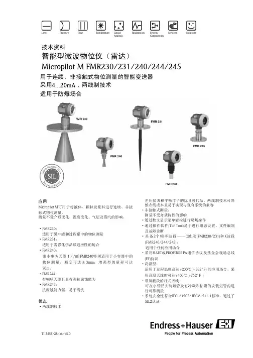
技术资料
智能型微波物位仪(雷达) Micropilot M FMR230/231/240/244/245
用于连续、非接触式物位测量的智能变送器 采用4...20mA 、两线制技术 适用于防爆场合
远程操作 ·采用HART手操器DXR 375; ·采用个人计算机、Commubox FXA l91/195及操作软件“ToF Tool-FieldToolPackage”和
“FieldCare”。
Endress + Hauser
3
Micropilot M
通过PROFIBUS PA的系统集成 总线上最多可连接32台变送器(应用于防爆级别为EEx ia IIC的区域中时,根据FISCO模式最多可 安 装8台变送器 )。 段耦 合器 为总 线提 供电 源。 既可 现场 操作 也可 远程操 作仪 表。完整 的测 量系 统包括:
一种基于脉冲涡流无损检测技术的硬度分选仪的设计

一种基于脉冲涡流无损检测技术的硬度分选仪的设计白杨;王益祥【摘要】This paper describes a kind of hardness sorter based on nondestructive testing technology. The field programmable gate array is taken as the central control platform. and the frequeney of DDS signal generator based on FPGA is used to modulate its pulses. At the same time the signal acquisition circuit is designed.The software synchronization sampling technique is used to col ect the feedback status data and then pick up the data related to the hardness of material. At last,the correlativity between the hardness of material and characteristic data is established to distinguish the hardness status.%基于脉冲涡流无损检测技术的硬度分选仪,以FPGA作为核心控制平台,采用DDS技术发出频率可调节的脉冲波,并设计了相应的信号采集电路,通过软件同步采样技术采集反馈的状态数据,然后通过对状态数据的主成分分析,提取出和材料硬度相关的数据信息,最后通过最小二乘法建立起特征数据与材料硬度的相关关系,从而最终实现判断钢铁材料硬度状态的目的。
【期刊名称】《机械制造与自动化》【年(卷),期】2014(000)003【总页数】4页(P28-31)【关键词】脉冲涡流;无损检测;DDS;硬度分选【作者】白杨;王益祥【作者单位】南京理工大学机械工程学院,江苏南京210094;南京理工大学机械工程学院,江苏南京210094【正文语种】中文【中图分类】TH12;TM921.520 引言目前我国的钢铁产业已经形成了相当大的规模,但在实际的钢铁生产过程中,由于始终无法保证高品质的热处理工艺,使得钢铁件在经过热处理以后出现硬度过高或者硬度不足的现象常有发生,造成资源的极大浪费。
网络高清电梯楼层信息叠加器 NE-GQ6000N-DT说明书
恩易物联电梯楼层信息叠加器NE-GQ6000N-DT操作手册V1.1山东恩易物联技术有限公司恩易物联声明本手册适用于支持网络摄像机的电梯楼层信息叠加器(NE-GQ6000N-DT)。
本手册可能包含技术上不准确的地方或印刷错误。
本手册的内容将做不定期的更新,恕不另行通知;更新的内容将会在本手册的新版本中加入。
我们随时会改进或更新本手册中描述的产品或程序。
若存在手册中对产品的描述与实物不符,一律以实物为准。
注意事项·电梯楼层显示器上不能放置盛有液体的容器(例如水杯)。
·将电梯楼层显示器放置在通风良好的位置。
·电梯楼层显示器工作在允许的温度及湿度范围内。
·电梯楼层显示器内电路板上的灰尘在受潮后会引起短路,请保证电梯楼层显示器所处环境的干爽。
·配备电梯平层传感器收发端积尘过多会影响电梯楼层显示器的正常工作,务必保证电梯平层传感器收发端干净清洁。
恩易物联目录1 产品介绍 (4)1.1 产品概述 (4)1.2 功能特点 (4)1.3 型号说明 (5)1.4 物品清单 (5)2 产品描述 (6)2.1 硬件设备参数 (6)2.1.1 接口说明 (6)2.1.2 技术参数 (7)2.2 平层传感器参数 (7)2.2.1 平层传感器示意图 (8)2.2.2 传感器技术参数 (8)2.3 设备配置 (9)2.3.1配置软件 (9)2.3.2配置说明 (11)3 硬件安装 (14)3.1 安装须知 (14)3.2 安装拓扑图 (15)3.2 传感器安装 (15)4 快速安装指南 (16)快速安装 (16)5固件升级 (17)5.1网络升级 (17)5.1.1硬件准备 (17)5.1.2软件准备 (17)5.1.3升级流程 (18)5.2串口升级 (20)6常见问题 (21)7服务与支持 (21)8联系方式 .................................................................................................................... 错误!未定义书签。
Minotaur MSR132E ED监测安全超声波传感器说明书
Installation InstructionsOriginal InstructionsMinotaur MSR132E/ED Monitoring Safety RelayCatalog Number 440R-E23159, 440R-E23160, 440R-E23161, 440R-E23162, 440R-E23191, 440R-E23192, 440R-E23193, 440R-E23194, 440R-E23195, 440R-E23097, 440R-E23098Summary of ChangesThis publication contains the following new or updated information. This listincludes substantive updates only and is not intended to reflect all changes.IntroductionThis device is intended to be part of the safety-related control system of amachine.Rockwell Automation does not accept responsibility for the failure of this device ifyou do not implement the procedures that are given in this publication, or if youuse the unit outside the recommended specifications that are listed in thispublication.DescriptionIf both internal relays activate, the safety output contacts close. The two statusindicators in the front indicate the status of the relays. The N.C. contact X1-X2must connect to the feedback loop of the control unit to monitor the safe functionor the MSR132E/ED. The off-delay versions of MSR132ED are active until the fixeddelay time runs down. All MSR series safety relays can connect to the contactmodule MSR132E/ED. The use of single or dual-channel activation depends on thelevel of safety that is required for the control unit. The off-delay versions are onlyavailable for DC supply and are limited to Cat 3 applications. Available time ranges0.5 s/1 s/2 s/3 s. Versions with removable terminals end with P.Pay attention to Wiring Examples on page3.Topic PageUpdated Declaration of Conformity4IMPORTANT Before installation, perform a risk assessment to determinewhether the specifications of this device are suitable for allforeseeable operational and environmental characteristicsof the machine to which it is to be fitted. At regularintervals during the life of the machine, check whether thecharacteristics foreseen remain valid.WARNING: Danger of serious injuries. Misuse can result inmalfunction.•Only authorized and trained personnel can start up, assemble,or retrofit the device.•Installation must be in accordance with the following steps.WARNING: Danger of serious injuries.Incorrect installation or manipulation can result in seriousinjuries. Do not defeat, tamper, remove, or bypass this unit.ATTENTION: If any malfunction or damage is present, do notattempt to repair. Replace the unit before machine operationis allowed. Do not dismantle the unit.IMPORTANT The safety inputs of these products are described asnormally closed (N.C.), that is, with the guard closed, theactuator in place (where relevant), and the machine able tostart. You must prevent exposure to shock and/or vibrationin excess of those specifications in IEC 60068 part: 2-6/7.Adherence to the recommended inspection andmaintenance instructions forms part of the warranty.IMPORTANT All information complies with the state of this publicationand is subject to change without notice.2Rockwell Automation Publication 440R-IN090A-EN-P - November 2022Minotaur MSR132E/ED Monitoring Safety Relay Installation InstructionsSpecificationsInstallationDo not install this product until the installer obtains a copy of the instructions of the manufacturer, in a language that they can understand. This instruction publication is available in multiple languages at rok.auto/literature .Figure 1 - MountingMount the enclosure to a minimum of IP54.Figure 2 - Removable Terminals (P versions only)To remove the terminals, insert a screwdriver and slowly move as shown in Figure 2.AttributeMSR132EMSR132EDFunctional safety dataAccording to ISO 13849-1:•PLe, Cat. 4•MTTF d [a]: 452•DC average: 99%According to ISO 13849-1:•PLd, Cat. 3•MTTF d [a]: 452•DC average: 99%According to IEC 62061 and IEC 61508:•SIL 3 •PFH [1/h]: 234E-10•HFT: 1•DC: 99%According to IEC 62061 and IEC 61508:•SIL 2•PFH [1/h]: 234E-10•HFT: 1•DC: 99%•TM (PTI) [a]: 20•dop [d]/hop [h] (1): 365/24•tcycle [h]/[s] (2): 8/28,800(1)Operation time (day, hour)(2)Cycle time (hour, sec)Power supply 24V AC/DC (delay types only DC)0.85...1.1 x rated voltage 50/60 Hz Power consumption 3 W Input simultaneity InfiniteAllowable input resistance, max 160 ΩOutputs 4 N.O. safety, 2 N.C. auxiliary, 1 N.C. monitoring Output rating •UL: B300, R3006 A/250V AC, 3 A/24V DC •AC-15: 6 A/250V AC •DC-13: 3 A/24V DC Fuses output (external) 6 A slow blow or 10 A quick blow Switched current/voltage, min 10 mA/10V Contact material AgSnO 2 + 0.5µAu AgSnO 2 + 0.5µAuElectrical life (operations)•100,000 (220V AC/4 A/880VA cos φ = 0.35)•500,000 (220V AC/1.7 A/375VA cos φ = 0.6)•1,000,000 (30V DC/2 A/60 W)•2,000,000 (10V DC/0.01 A/0.1 W)Mechanical life 10,000,000 cycles Power on delay < 50 msResponse time < 100 ms (or 0.5 s, 1 s, 2 s, 3 s)Impulse withstand voltage 2500V Pollution degree 2Installation group Overvoltage category III, VDE 0110-1Operating temperature -5…+55 °C (23…131 °F)Relative Humidity 90% Enclosure protection IP40 (NEMA 1)Terminal protection IP20Wiring Use copper that withstands 60/75 °C (140/167 °F)Conductor size 0.2...2.5 mm 2 (24…12 AWG)Torque settings Terminal screws: 0.6…0.8 N•m (5…7 lb•in)Case material Polyamide PA 6.6Mounting 35 mm (1.38 in.) DIN rail in enclosure to a minimum of IP54Weight 215 g (0.47 lb)Vibration 10…55 Hz, 0.35 mm (0.01 in.)Rockwell Automation Publication 440R-IN090A-EN-P - November 20223Minotaur MSR132E/ED Monitoring Safety Relay Installation InstructionsWiring ExamplesFigure 3 - 24V DC Host (MSR131) with Dual-channel Safety Light Curtain Input and Single-channel Delayed Expansion (MSR132ED) with MonitoringFigure 4 - 24V DC Host (MSR138) with Dual-channel Safety Light Curtain Input and Dual-channel Expansion (MSR132E) Delayed with Adjustable Timed MSR138 OutputsCircuit DiagramFigure 5 - DiagramApproximate DimensionsFigure 6 - Dimensions [mm (in.)]ActiveClosedTable 1 - Circuit Diagram ExplanationAbbreviation Description MSR132E/MSR132 EP MSR132ED/MSR132 EDP A1, A2-PowerX1, X2-Monitoring loop feedback 13, 14, 23, 24, 33, 34, 43, 4417, 18, 27, 28, 37, 38, 47, 48Safety output (N.O.)51, 52, 61, 6255, 56, 65, 66Auxiliary output (N.C.)Table 2 - Status IndicatorsIndicator Description PWR Status indicator illuminates green when the unit is powered, flashing green ifcross-loop faults occurCH1Status indicator illuminates green when the safety output channel 1 activates CH2Status indicator illuminates green when the safety output channel 2 activatesPublication 440R-IN090A-EN-P - November 2022 | Supersedes Publication 440R-IN062A-MU-P - April 2011Copyright © 2022 Rockwell Automation, Inc. All rights reserved. Printed in the U.S.A.Allen-Bradley, expanding human possibility, Guardmaster, Minotaur, and Rockwell Automation are trademarks of Rockwell Automation, Inc.Trademarks not belonging to Rockwell Automation are property of their respective companies.10000176980 Ver 01Rockwell Otomasyon Ticaret A.Ş. Kar Plaza İş Merkezi E Blok Kat:6 34752, İçerenköy, İstanbul, Tel: +90 (216) 5698400 EEE Yönetmeliğine UygundurYour comments help us serve your documentation needs better. If you have any suggestions on how to improve our content, complete the form at rok.auto/docfeedback .For technical support, visit rok.auto/support .Waste Electrical and Electronic Equipment (WEEE)Rockwell Automation maintains current product environmental compliance information on its website at rok.auto/pec .At the end of life, this equipment should be collected separately from any unsorted municipal waste.Safety SpecificationsYou can use the MSR132E/ED safety relay in safety circuits according to DIN EN 60204-1/VDE 0113 part 1. Safety requirements that are specified inSpecifications on page 2 are maximum, based on the operation mode and wiring.Specifications are applicable only if the safety function is demanded at least once within 6 months. All diagnostic tests are conducted at least before next demand. The mission time (TM) for the proof test interval (PTI) is adopted. Components failure rates according to SN29500.Figure 7 - Example Safety CircuitsDeclaration of ConformityCE ConformityRockwell Automation declares that the products that are shown in this document conform with the Essential Health and Safety Requirements (EHSRs) of the European Machinery Directive (2006/42/EC) and EMC Directive (2014/30/EU).For a comprehensive CE certificate visit: rok.auto/certifications .UKCA ConformityRockwell Automation declares that the products that are shown in this document are in compliance with the Supply of Machinery (Safety) Regulations (2008 No. 1597) and Electromagnetic Compatibility Regulations (2016 No. 1091).For a comprehensive UKCA certificate visit: rok.auto/certifications.。
MOELLER A22系列按钮和指示灯 说明书
- -
A22 -RS3 254433 A22- RS3- KMS1- A4 254434
5件 5件
编码组件
用于设定和改变自锁定/弹簧复位功能和钥匙抽出部位, 由2个部件组成 -
A22 -SP-RMQ 254507
5件
标记说明:
锁定 弹簧复位
8
A22
带灯按钮头, 示灯 指
颜色
型号
订货号
价格 见价格表
5件
4
A22
表面安装成套按钮, IP65
安装孔 数目
触点序号
按钮盒颜色
型号
订货号
价格
见价格表
标准 包装
按钮
平头按钮
1
1M
1B
14 22 13 21
A22-RD-11/KC/I 254417
1件
1
1M
1B
14 22 13 21
A22-RD-10/KC/I 254418
1件
触点配置 M = 常开, B = 常闭 = 通过强制分断而 实现的安全功能,符合 IEC/EN 60947-5-1
5件
蘑菇头按钮头
弹簧复位
A22-RP-GN 11 254424 A22-RP-RT10 254425
5件 5件
7
A22系列按钮和指示灯
按钮头
A22
选择开关头, 匙操作开关头 钥
功能
钥匙抽出 位置
颜色
型号
订货号
价格 见价格表
标准 包装
A22系列按钮和指示灯
选择开关头, IP65
2位 拇指手柄
60˚ 45˚ A22 -RWK1R 254428 A22 -RWK1 254429 A22 -RWK1V 261369
Schneider_KNX产品目录
包装单位
PG
备注
热塑材料,磨光
纯白 烟灰 银灰
MTN662119
1/100
9
MTN662114
1/100
9
MTN662160
1/100
9
耐划性好的热固塑料: 对这些产品请使用光亮热塑材料
设计系列空白盖板
设计系列。 盖板可以用螺栓固定,适合齐平安装式总线耦合器 或齐平安装式执行器。
小型逻辑模块
借助REC小型功能模块,用户可以通过INSTABUS EIB完成各种控制和调节功能。接收到的总线控制信 号将被模块破译,并按照可自由编程的逻辑或数学 功能进行处理。处理结果将以控制信号的形式通过 总线发送给相应的执行器(不采用浮点格式)。设 备的编程工作通过INSTABUSEIB(不带内置RS 232 接口)完成。项目范围包括150个功能信息组和200 个组地址。该小型功能模块的项目也可以由REG功 能模块来进行加工处理。通过一个实时操作系统负 载控制和管理,采用一种图形语言来编程的功能元 件。内置实时定时器按照设定时间标准完成控制操 作。可以用一个功能元件库根据实际需求制定出通 用的应用程序,如:全套供暖、照明和百叶帘的控 制程序。使用小型功能模块工具软件,用户可以在 功能元件库中对大约40个带不同标准化EIB数据控 制信号的功能元件进行选择,并将特定的应用程序 与选择出的元件相互匹配。这些程序随后将载入设 备并执行相应功能。工作电源:需要通过数据导轨 数据条的两个外部导线以及数据导轨数据条连接器 REG/4来提供直流29V电压,数据导轨的两条外部线 路需要带有DC29V电压。 电流消耗:正常运行情况下约40mA 编程运行情况下约100MA 模块宽度:3模数=约54mm
电源电压:AC 230 V, 50-60 Hz 输出电压:DC 29 V±1 V 输出电流:最大640mA, 防短路 模块宽度:7 模数 = 约 126 mm
- 1、下载文档前请自行甄别文档内容的完整性,平台不提供额外的编辑、内容补充、找答案等附加服务。
- 2、"仅部分预览"的文档,不可在线预览部分如存在完整性等问题,可反馈申请退款(可完整预览的文档不适用该条件!)。
- 3、如文档侵犯您的权益,请联系客服反馈,我们会尽快为您处理(人工客服工作时间:9:00-18:30)。
金属结构/零件表面疲劳裂纹M2便携式掌上涡流探伤仪
厂家:德国罗曼公司
型号: M2(JECO中文版)
订货编号JECO - M2-V3
一、M2主机性能:
1、M2多功能手持式主机:小型化、智能化、全功能涡流仪的典范,采用微计算机智能化技术和数字信号处理技术,是适合
便携式多种涡流检测复杂应用的功能强大而
先进的手持式单手操作平台:
-表面缺陷检测;
-近表面缺陷检测/隐藏缺陷检测;
-高速旋转检测;
-硬度分选;
-材质分选;
-热处理分选;
2、嘉盛中文菜单,其他德、英、法、意、瑞、
西语可选;只有一级子菜单,象形图标导
引菜单,操作方便,无需专门的涡流知识。
3、频率响应范围10Hz-12MHz,连续可调,
显示单位可以是Hz, kHz, MHz;频率稳定性达50PPM,额定误差低于1%,检测信号稳定,重复性好。
4、重量:900克(包括电池),重心位于掌心;人体工程学设计,“T”型体积
仅为320x125x73mm。
操作者可以平衡舒适地单手握持仪器,拇指操作键盘,另一手运动探头。
重心位于掌心,保证检测过程中您的手不会疲劳。
5、旋转检测900rpm-2700rpm可十档调节旋转枪转速,带扭矩补偿。
6、增益:
-前置放大:0 – 60 dB, 0.5 dB步进(100 kHz以下0 - 40 dB);
-增益:0 – 60 dB, 0.5 dB步进;
-Y轴扩展:0 – 20 dB, 1 dB步进;
-前置放大和增益自动选择。
7、相位:0° - 359.5°,0.5°步进;步进大小可调节。
8、滤波:
-低通1.3 Hz – 10 kHz, 40步进;
-高通0 Hz – 10 kHz, 40步进;
-带通0 Hz – 10 kHz,还可混合低通和高通;
- 旋转检测还可选择自动滤波功能。
9、显示屏:
-80x60mm高清晰度LCD显示屏,带LED
背景光;
-80°大视角;
-320x240像素,刷新频率75Hz;
-220,000数据采样/秒,信号无延时;
-信号可100%满屏显示,带菜单显示
89%;
-对比度设定带温度补偿;
-黑暗至亮太阳光范围内在任何光线下
高对比度显示。
10、信号显示模式:
-阻抗平面图/斑点模式显示(X/Y),适合任何探头;
-时基/扫描模式(Y/t)显示,5毫秒至60秒十七档可调,同步;
-双屏显示:阻抗-时基双屏显示模式;
-可选择的显示模式:X/Y在中心原点,X/Y在原点底部,X/Y在原点右底部;-样件信号可作为背景显示;
-双屏显示格栅大小和灰度可调;
-零点和空载点可自由定位;
-旋转操作时自动触发;
-旋转操作时可选择瀑布显示模式;
-信号显示保持0.1秒至70秒十二档可调;
-屏幕信号可直接存储;
-信号可人工清除或2-80秒设定自动清屏。
11、门限和报警:
-报警:发光或发声报警;
-所有显示模式均有效,并可反向;
-门限可调节:Y轴门限、方框门限、圆圈门限均可沿Y轴水平调节设定。
12、参数设置和图形存储:
- 99个用户自定义设置可编程、存储和调用;
- 55个出厂应用缺省设置(不可覆盖);
- 32个信号寄存器包括文档化参数设定;
- 参数设置和图像可用英文字母命名;
- 长时间X-和Y-信号记录(条带图),从20秒至
24小时,最大可达连续90,000分钟封包,没有数据
丢失。
13、通讯接口:
- 选配工作平台,RS232/USN接口连接电脑或打
印机(HP激光打印机或Epson LX80);
14、电池工作:
-锂电,连续工作8小时;
15、环境温度:
-操作温度-20°C至50°C,最大相对湿度85%;
-存放温度-30°C至80°C,最大相对湿度85%;
-电池充电温度0°C 至40°C,最大相对湿度85%。
16、键盘:拇指操作3 x 3键的键盘,直接功能键,有的可以由操作者定义其功能,操作简捷方便。
17、标准样件(选配):铝、铁磁性钢、钛、奥氏体不锈钢四种参考试块,裂纹深度0.2/0.5/1.0mm,宽度0.1mm,嵌于手柄表面,为操作者带来极大方便。
18、电源供电:
- 8小时锂电,外表采用先进的收缩性薄膜包装技术封装;
- 充电器输入100 – 250 VAC/50–60 Hz;
- 选购工作台输入电源88 – 265 VAC/47 –440 Hz,仪器直接工作并充电,还可同时对备用电池充电。
19、人性化附件:保护仪器,适应野外各种恶劣环境:
- 野外作业护套,防油、尘、风、雨、雪等,配背带
可肩背并配有腰带挂扣;
- 接口橡胶护套,防水防油;
- 多用途支架/挂架,适应各种工作环境,背面有菜单
简明提示便于操作者备忘;
- 电池线冲器,携带及其方便,随时可进行充电。
20、软件(选配):选购工作平台时,可选配PC软件,
用于从电脑向仪器调用参数设置。
M2具有以下显著优势:
z先进而成熟的技术、稳定的性能,为操作者完成检测任务、提高检测水平提供了有力的工具;
z功能强大,适应各种检测需求,大大提升操作者的可靠性和灵活性;
z成熟的中文菜单,为操作者带来方便,无须掌握深度的涡流知识;
z体积小,重量轻,人性化设计让操作者轻松操作,不易疲劳,深受用户喜爱;z工业化设计,适应野外恶劣环境,携带方便;
z外场一个人操作:仪器只需单手操作,包括所有键盘;操作者另手可方便地
操作探头进行检测。
其他品牌的仪器一手握持时,需另手操作键盘,工作中须停下探头的扫查,或许另一人协助操作,无法做到单人操作,因而很难适应外场工作。
二、罗曼各种涡流探伤探头
1、特点:
- 追求卓越的品质,采用德国最好的材料和工艺;
- 性能稳定可靠、灵敏度高、重复性好、不误报;
- 精致耐用,耐磨损,长久的使用寿命;
- 完全与仪器性能匹配。
2、手持式检测探头:
如:裂纹探头、腐蚀探头、铆钉头探头、螺栓孔检测探头、紧固件检测探头、轮毂检测探头、原位检测探头等,还可根据客户要求定做。
3、内孔旋转检测探头和平面旋转检测探头:
可根据客户要求定做
具体应用请垂询我司。