四通道说明书(中英文混合)
四通道直接作用和助动阀门的应用说明书
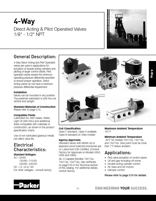
C1General Description:4-Way Direct Acting and Pilot Operated valves are used in applications foractuation of double acting cylinders and piloting of larger control valves. Pilot operated valves require the minimum operating pressure differential specified to ensure proper operation. Direct Acting valves do not have a minimum pressure differential requirement.InstallationValves can be mounted in any position. The preferred orientation is with the coil vertical and upright.Standard Materials of Construction Please refer to page C15.Compatible FluidsLubricated Air, Inert Gases, Water, Light Oil (300 SSU) and additional fluids compatible with materials of construction, as shown in the product specification charts.Use of non-lubricated gaseous media can affect valve life.ElectricalCharacteristics:Standard Voltages: AC – 24/60120/60–110/50 240/60–220/50DC – 12, 24 & 120For other voltages – consult factoryCoil Classification:Class F standard, Class H available Class B standard on V9xx models Agency Approvals:Standard valves with NEMA 4X orexplosion proof solenoid enclosures are UL Listed and CSA Certified. (Consult Factory for Approvals on Models V933, V935 and V955).SIL-3 Capable (Models 73417xx, 74417xx, 73477xx). See certificate on page F20 in the Technical section of this catalog. For additional details, consult factory.Maximum Ambient Temperature 167°FMinimum Ambient Temperature -40°F for models 73417xx, 74417xx and 73477xx. Dew point must be more than 7°F below ambient.Applications:• Pilot valve actuation of control valves • Oil and gas including off-shore • Double acting cylinder control • Air vises and Air motors •Damper controlPlease refer to page C15 for details.4-WayDirect Acting & Pilot Operated Valves 1/8" - 1/2" NPT4-WayC2Parker Hannifin Corporation Fluid Control Division180****8305(1800Valve05) /fcd43/83/160.75012524160NBR71417BN3SN0071417BN3SNR171417BN3SNM010C9 *Minimum ambient temperature: -40°F (-40°C). Dew point must be more than 7° F below ambient temperature.** Cv=0.45 with built-in metering control (Digits 11 and 12 are R1)3/83/160.75012524160NBR71477BN3SN0071477BN3SNR1-10C9 * Minimum ambient temperature: -40°F (-40°C). Dew point must be more than 7° F below ambient temperature.** Cv=0.45 with built-in metering control (Digits 11 and 12 are R1)C3Parker Hannifin CorporationFluid Control Division180****8305(1800Valve05)/fcd4-Way1/41/163/320.100.141/163/320.100.14010010130NBR V933LB2100V933LEF2100*C51/43/323/320.160.143/323/320.160.147510130NBRV933LB2075V933LEF2075*C51/41/163/320.100.141/161/80.080.180********NBR V935LB2100V935LEF2100*C51/43/323/320.160.143/321/80.140.217510130NBR V935LB2075V935LEF2075*C51/41/161/80.080.181/161/80.080.180********NBR V955LB2100V955LEF2100*C51/43/321/80.140.183/321/80.140.2107510130NBR V955LB2075V955LEF2075*C5Voltage 24/60120/60240/6012VDC 24VDC Coil CodeAB2A7W AB6A0Z AB8B6A DC1A3X DC2A4Y Coil Part Number*V57724F24V57731F24V57734F24V57727F24V57730F24*When ordering a replacement coil, use Coil Part Number (not Coil Code)Select the series V9 pressure vessel number from above and follow with the coil/enclosure number based on voltage from Fig. 1. Example V935LB2150 for 120/60 becomes part number V935LB2150AB6A0Z.*Fig. 1AC Power Consumption Rating VA Holding VA Inrush 17.532.5DC Power Consumption Rating 12 VDC 24 VDC 120 VDC 0.710.350.07C4Parker Hannifin CorporationFluid Control Division180****8305(1800Valve05)/fcd41/411/640.5530150 1.5150NBR 73477BN2KN0073477BN2KNM073477BN2KN7A 11C31/41/4 1.203015010167NBR 73477BN2PN0073477BN2PNM073477BN2PN7A 7C31/41/4 1.2030150 1.5150NBR 73477BN2PN0073477BN2PNM073477BN2PN7A11C31/41/4 1.20301500.6150NBR 73477BN2PN90--12C31/25/8 4.003015010167NBR 73477BN4UN0073477BN4UNM073477BN4UN7A 7C111/25/8 4.0030150 1.5150NBR 73477BN4UN0073477BN4UNM073477BN4UN7A11C111/25/84.00301500.6150NBR73477BN4UN90--12C111/411/640.5530150 1.5150NBR 73417BN2KN0073417BN2KNM073417BN2KN7A 11C11/41/4 1.203015010167NBR 73417BN2PN0073417BN2PNM073417BN2PN7A 7C11/41/4 1.2030150 1.5150NBR 73417BN2PN0073417BN2PNM073417BN2PN7A11C11/41/4 1.20301500.6150NBR 73417BN2PN90--12C11/25/8 4.003015010167NBR 73417BN4UN0073417BN4UNM0-7C101/25/8 4.0030150 1.5150NBR 73417BN4UN0073417BN4UNM0-11C101/25/84.00301500.6150NBR73417BN4UN90--12C10C5Parker Hannifin CorporationFluid Control Division180****8305(1800Valve05)/fcd4-Way1/411/640.5530150 1.5150NBR 73417VN2KN0073417VN2KNM073417VN2KN7A11C11/411/640.55301500.6150NBR 73417VN2KN90--12C11/41/4 1.203015010167NBR 73417VN2PN0073417VN2PNM073417VN2PN7A 7C11/41/41.20301501.5150NBR73417VN2PN0073417VN2PNM073417VN2PN7A11C11/41/41.201501.5150NBR74417BN2PN00--11C4* External pilot pressure to operate valve must be 30 - 150 psi.1/411/640.5530150 1.5150NBR 73477VN2KN0073477VN2KNM073477VN2KN7A11C31/411/640.55301500.6150NBR 73477VN2KN90--12C31/41/4 1.203015010167NBR 73477VN2PN0073477VN2PNM073477VN2PN7A 7C31/41/41.20301501.5150NBR73477VN2PN0073477VN2PNM073477VN2PN7A11C3C6Parker Hannifin CorporationFluid Control Division180****8305(1800Valve05)/fcd41/41/41.003015010167NBR73419AN2NN0073419AN2NNM0-7C21/411/640.550150 1.5150NBR 74417VN2KN00--11C41/41/4 1.20015010167NBR 74417VN2PN00--7C41/41/41.201501.5150NBR74417VN2PN00--11C4* External pilot pressure to operate valve must be 30 - 150 psi.C7Parker Hannifin CorporationFluid Control Division180****8305(1800Valve05)/fcd4-Way 2 position single solenoidPort identification:Press-1/Cyl - 2,4/ EXH - 3,54-Way 2 position single solenoidPort identification:Press-P/A-Cylinder/ EA-Exhaust/B-Cylinder/ EB- ExhaustC8Parker Hannifin Corporation Fluid Control Division180****8305(1800Valve05) /fcd42.59 Valve Reference C44-Way 2 position dual solenoidPort Identification:Press-1/CYL-2,4/EXH - 3,54-Way 2 position solenoidexternal pilotPort Identification:Press-1/CYL-2,4/EXH - 3,5C9Parker Hannifin CorporationFluid Control Division180****8305(1800Valve05)/fcd4-Way4-way direct actingV933xx: Normally Closed-Normally Closed v935xx: Normally Closed-Normally Open v955xx: Normally Open-Normally Open4-way 2 position single solenoid Port identification:pressure-1/cyl.A-2/cyl.B-4/exh.A-3/exh. B-5V933xx V935xx V955xxC10Parker Hannifin Corporation Fluid Control Division180****8305(1800Valve05) /fcd44-Way 2 position single solenoidPort identification:pressure-1/cyl.A-2/cyl.B-4/Exh.A-3/Exh. B-54-Way 2 position single solenoidPort identification:de-energized: pressure to AB to exhaustenergized: pressure to BA to exhaust4-Way4-Way 2 position single solenoidPort Identification:Press-1/CYL-2,4/EXH - 3,54-Way 2 position single solenoid4-Way 2 position dual solenoidPort Identification:Press-P/CYL-A,B/EXH - EC12Parker Hannifin CorporationFluid Control Division180****8305(1800Valve05)4-Way 2 position dual solenoid Port Identification:1-Pressure/2, 4-Cylinder/3, 5-Exhaust4-Way V933 Four-Way Normally Closed - Normally Closed ValvesWhen de-energized, both inlet portsare closed by the two plungerspreventing flow from the common inletthrough both of the valves. The cylindercommon exhaust, permitting flow fromthe cylinders to the exhaust. Whenthe coils are energized, both valveplungers rise, opening the inlet orifices,orifices in the sleeves. This stops flowfrom the cylinder ports to the exhaust,and permits flow from the inlet to thecylinder ports.The plungers of the two valves areat opposite positions in both theopen valve, through the sleeve, andout the cylinder port of the valve. At theexhaust. Therefore, fluid flows from theinlet of the valve to the cylinder port ofthe normally open valve and from thecylinder port of the normally closedvalve to the exhaust. When energized,the two valves reverse in position.Typical cylinder operation with V933 ValvesBoth coils de-energized. The inlet pressure is closed to both sides ofa double-acting cylinder. Side #1 and Side #2 of the cylinder are opento exhaust through cylinder ports #C1 and #C2. The piston can beCoil of valve #1 energized; coil of valve #2 de-energized. The inlet pressureis open to side #1 of the double-acting cylinder through cylinder port #C1,the exhaust is closed off by the plunger insert. Side #2 of the cylinder isopen to exhaust through cylinder port #C2, the inlet is closed off by theplunger insert. The piston moves to the right.Typical cylinder operation with V935 ValvesBoth coils de-energized. The inlet pressure is open to side #2 of the double-acting cylinder through cylinder port #C2 and the plunger insert closes off theexhaust. Side #1 of the cylinder is open to exhaust through cylinder port #C1and the inlet pressure is closed off. This causes the piston in the cylinder toBoth coils energized. The inlet pressure is open to side #1 of the cylinderthrough cylinder port #C1 and the exhaust is closed off. Side #2 of thecylinder is open to the exhaust through cylinder port #C2 and the inletpressure is closed off by the plunger insert. The piston moves to the right.4V955 Four-Way Normally Open - Normally Open ValvesBoth plungers are in the same positionwhen the coils are de-energized. Inthis condition, fluid flows through thecommon inlet of the body, up throughthe sleeves of both valves, and outthe cylinder ports of the valves. Bothorifices in the sleeve stops are closedto the exhaust ports by the plunger.In the energized position, both valveplungers operate together to closethe inlet ports, stopping flow into thevalve. At the same time, the orifices inthe sleeves are opened permitting flowfrom the cylinder ports to the commonexhaust port in the body.Typical cylinder operation with V955 ValvesBoth coils de-energized. The inlet pressure is open to both sides of thedouble-acting cylinder through cylinder port #C2 and the plunger insertcloses off the exhaust. Side #1 of the cylinder is open to exhaust throughcylinder port #C1 and the inlet pressure is closed off. This causes the pistonin the cylinder to move to the left.Coil of valve #1 energized; coil of valve #2 de-energized. The inletpressure is closed to side #1 of the double-acting cylinder and open toexhaust through cylinder port #C1. Side #2 of the cylinder is open tothe inlet pressure, through cylinder port #C2. The exhaust is closed offby the plunger insert. The piston moves to the left.4-Way Pilot Piped Materials of Construction**Product*WattTypePort SizeBodySleeve TubeSleeve Stop Sleeve Flange "Plunger Blank"Plunger Spring ShadingRingMax.AmbientTemp.73417AN 105/21/4Alum 304SS 430FR 430F 430FR 18-8SS Copper 167°F73417BN 105/21/4Brass 304SS 430FR 430F 430FR 18-8SS Copper 167°F 73417BN 105/21/2Brass 304SS 430FR 430F 430FR 18-8SS Copper 167°F 73417VN 105/21/4303304SS 430FR 430F 430FR 18-8SS Copper 167°F 73419AN 105/21/4Alum 304SS 430FR 430F 430FR 18-8SS Copper 167°F 7341LAN 105/21/8Alum 304SS 430FR 430F 430FR 301SS Copper 150°F 7341LMN 105/21/4Zinc 304SS 430FR 430F 430FR 301SS Copper 150°F 73477BN 105/21/4Brass 304SS 430FR 430F 430FR 18-8SS Copper 167°F 73477BN 105/21/4Brass 304SS 430FR 430F 430FR 18-8SS Copper 167°F 73477BN 105/21/2Brass 304SS 430FR 430F 430FR 18-8SS Copper 167°F 73477VN 105/21/4303304SS 430FR 430F 430FR 18-8SS Copper 167°F 74417BN 105/21/4Brass 304SS 430FR 430F 430FR 18-8SS Copper 167°F 04F48S2114/21/4Brass 305SS 430FR 430F 430FR 302SS Copper 77°F 04F48S211.54/21/4Brass305SS430FR430F430FR302SSCopper77°F* Shows first 4 or 7 digits of pressure vessel part number.** Maximum ambient temperature shown is the rating when valve is operating at the maximum fluid temperature as shown in the product sections for each of the valves in this catalog.4-Way Direct Acting Materials of Construction**Product*WattTypePort SizeBodySleeve TubeSleeve Stop Sleeve Flange "Plunger Blank"Plunger Spring ShadingRingMax.AmbientTemp.71417BN 244/21/4 - 3/8Brass 304SS 430FR 430F 430FR 18-8SS Copper 140°F 71477BN 244/21/4 - 3/8Brass 304SS 430FR 430F 430FR 18-8SS Copper 140°F V93320NC-NC 1/4Aluminum 304SS 430FR 430F 430FR 18-8SS Copper 122°F V93520NC-NO 1/4Aluminum 304SS 430FR 430F 430FR 18-8SS Copper 122°F V95520NC-NC1/4Aluminum304SS430FR430F430FR18-8SSCopper122°FC16Parker Hannifin CorporationFluid Control Division180****8305(1800Valve05)4NotesGeneral Description: The NAMUR mounting interface for direct mount pilot valves has become widely popular around the world. Parker's Direct Mount NAMUR valves meet that global need and are supplied with the necessary mounting hardware and seals as standard to ensure proper mounting, interface sealing and valve function. These valves can be converted between 3-way and 4-way operation by using Parker's patented mounting conversion plate which is unique in the industry. (See Conversion Plate Kit on P. C22)InstallationValves can be mounted in any position. The preferred orientation is with the coil vertical and uprightStandard Materials of ConstructionPlease refer to page C22. Compatible FluidsLubricated Air and Inert Gases.Use of non-lubricated gaseous media can affect valve life. Electrical Characteristics:Standard Voltages:AC – 24/60120/60–110/50240/60–220/50DC – 12, 24 & 120For other voltages – consult factory Coil Classification:Class F standardClass H availableAgency Approvals:Standard valves with NEMA Type 4Xor explosion proof solenoid enclosuresare UL Listed and CSA Certified. Foradditional details, consult factory.SIL-3 Capable (Models 73417xxx,73477xxx). See certificate on page F20in Technical Section of this catalog.Please refer to page C22 for details.Minimum Ambient Temperature-40° F (Dew point must be more than7° F below ambient temp.Maximum Ambient Temperature167° FApplications:• Pilot valve actuationof larger control valves• Oil and gas applications includingoff-shore installations• Double acting cylinder controlrequiring direct pilot mount valves• Air Vises• Air Motors• Damper ControlDirect Mount NAMUR 3/2, 3-Way — 5/2, 4-WayDirect Acting and Pilot Operated Valves 1/4" - 1/2" NPTC18Parker Hannifin CorporationFluid Control Division180****8305(1800Valve05)43/2 3-Way 2 Position-Single Solenoid-NAMUR Direct Mount - AluminumPort Size NPTOrifice Size in.Flow FactorCv Operating PressureDifferential(MOPD) PSIWatt Max. Fluid Temp. °F Seal Pressure VesselReferenceMin.Air Inert Gas Coil Valve 1/43/320.17015010167NBR71315AKDKN007C121/41/41.203015010167NBR73417BKDPN0073417BKDPNM073417BKDPN7A7C13* External pilot pressure to operate valve must be 30-150 PSI.43-Way Normally ClosedPort Identification:5/2, 4-Way 2 Position Single SolenoidPort Identification:5/2, 4-Way 2 Position Single SolenoidPort Identification:5/2, 4-Way 2 Position Dual SolenoidPort Identification:C22Parker Hannifin Corporation Fluid Control Division180****8305(1800Valve05) /fcd44-Way Pilot Direct Mount Materials of Construction**Product*Watt Type PortSize BodySleeveTubeSleeveStopSleeveFlange"PlungerBlank"PlungerSpringShadingRingMax.AmbientTemp. 71315AK103WNC NAMUR Alum304ss430FR430F430FR19-8SS Copper167°F 73417AK103/2-5/21/4Alum304SS430FR430F430FR18-8SS Copper167°F 73417BK103/2-5/21/4Brass304SS430FR430F430FR18-8SS Copper167°F 73417VK103/2-5/21/4Brass304SS430FR430F430FR18-8SS Copper167°F 73477AK103/2-5/21/4Alum304SS430FR430F430FR18-8SS Copper167°F 73477BK103/2-5/21/4Brass304SS430FR430F430FR18-8SS Copper167°F * Shows first 7 digits of pressure vessel part number.** Maximum ambient temperature shown is the rating when valve is operating at the maximum fluid temperature as shown in the product sections for each of the valves in this catalog.Parker’s 3-way/4-way Conversion Mounting Plate KitThis conversion mounting kit, unique in the industry, allows acommon valve to be installed and used in either a 3-way or4-way function.Available with U.S., or Metric mounting screws. Consult factoryfor the specific kit number that meets your requirements.。
AtlasIED Atmosphere AZA404四通道网络放大器说明书

S o u n d L P . T h e A t l a s “C i r c l e A ”, S o u n d o l i e r , a n d A t l a s S o u n d a r e t r a d e m a r k s o f A t l a s S o u n d L .P . I E D i s a R e g i s t e r e d T r a d e m a r k o f I n n o v a t i v e E l e c t r o n i c D e s i g n s L L C . A l l r i g h t s r e s e r v e d . d e m a r k s a r e p r o p e r t y o f t h e i r r e s p e c t i v e o w n e r s . N o e n d o r s e m e n t i s i m p l i e d . D u e t o c o n t i n u a l p r o d u c t d e v e l o p m e n t , s p e c i f i c a t i o n s a r e s u b j e c t t o c h a n g e w i t h o u t n o t i c e . A T S 006181 R e v C 8/20AZA404Multi-Channel Network AmplifierApplicationsAZA Series amplifiers integrate with Atmosphere signal processors which makes them ideal for use in restaurants, presentation rooms,classrooms, conference rooms, and retail background / foreground music applications.General DescriptionThe AtlasIED Atmosphere AZA404 four-channel amplifier is designed to interface with the Atmosphere family of products, such as the AZM series of processors. The AZA amplifiers can be configured in three different configurations to meet the design requirements of any installation. These AZA models are factory preconfigured in a four-channel, 70V mode. If the design requires four channels of low impedance amplification, the AZA amplifiers can be configured as four-channel models with either 4Ω or 8Ω load impedances. Many system designs require both low and high impedance amplification. These AZA models can be configured to deliver 70V / 100V for apaging / background system on two (2) channels plus two (2) additional 4Ω or 8Ω amplifier channels for foreground stereo application.These AZA models come standard with four (4) balanced line inputs and an accessory slot for an optional four-channel Dante™ receiver card (model DPA-DAC4), giving the AZA404 and AZA804 a total of up to eight (8) inputs. All inputs can be mixed and routed to any of the four amplifier channels. All four (4) amplifier channels have an assortment of advanced DSP tools.The AZA404 is ready to use out of the box in four-channel, 70V mode, with no configuration or network connectivity required, making them easily paired for use with AtlasIED Atmosphere Signal Processors.Features• 4 Amplified Channels• AZA404 Configuration Power Levels • 4 x 100-Watt 70V (Factory Default) • 4 x 100-Watt 100V • 4 x 75-Watt @ 8Ω • 4 x 50-Watt @ 4Ω• 2 x 100-Watt 70V/100V & 2 x 75-Watt @ 8Ω • 2 x 100-Watt 70V/100V & 2 x 75 -Watt @ 4Ω• Integrates with Atmosphere AZM Zone Master • Energy Efficient• Convection Cool / Fan Assist • Accepts Low Z & Hi Z Loads• Onboard Web UI for Remote Monitoring of Status & Levels • Front Panel Power Switch Disable• APD - Auto Power Down with Audio Sense Turn On •Dante™ Optional Accessory Card SlotS o u n d L P . T h e A t l a s “C i r c l e A ”, S o u n d o l i e r , a n d A t l a s S o u n d a r e t r a d e m a r k s o f A t l a s S o u n d L .P . I E D i s a R e g i s t e r e d T r a d e m a r k o f I n n o v a t i v e E l e c t r o n i c D e s i g n s L L C . A l l r i g h t s r e s e r v e d . d e m a r k s a r e p r o p e r t y o f t h e i r r e s p e c t i v e o w n e r s . N o e n d o r s e m e n t i s i m p l i e d . D u e t o c o n t i n u a l p r o d u c t d e v e l o p m e n t , s p e c i f i c a t i o n s a r e s u b j e c t t o c h a n g e w i t h o u t n o t i c e . A T S 006181 R e v C 8/20S o u n d L P . T h e A t l a s “C i r c l e A ”, S o u n d o l i e r , a n d A t l a s S o u n d a r e t r a d e m a r k s o f A t l a s S o u n d L .P . I E D i s a R e g i s t e r e d T r a d e m a r k o f I n n o v a t i v e E l e c t r o n i c D e s i g n s L L C . A l l r i g h t s r e s e r v e d . d e m a r k s a r e p r o p e r t y o f t h e i r r e s p e c t i v e o w n e r s . N o e n d o r s e m e n t i s i m p l i e d . D u e t o c o n t i n u a l p r o d u c t d e v e l o p m e n t , s p e c i f i c a t i o n s a r e s u b j e c t t o c h a n g e w i t h o u t n o t i c e . A T S 006181 R e v C 8/20S o u n d L P . T h e A t l a s “C i r c l e A ”, S o u n d o l i e r , a n d A t l a s S o u n d a r e t r a d e m a r k s o f A t l a s S o u n d L .P . I E D i s a R e g i s t e r e d T r a d e m a r k o f I n n o v a t i v e E l e c t r o n i c D e s i g n s L L C . A l l r i g h t s r e s e r v e d . d e m a r k s a r e p r o p e r t y o f t h e i r r e s p e c t i v e o w n e r s . N o e n d o r s e m e n t i s i m p l i e d . D u e t o c o n t i n u a l p r o d u c t d e v e l o p m e n t , s p e c i f i c a t i o n s a r e s u b j e c t t o c h a n g e w i t h o u t n o t i c e . A T S 006181 R e v C 8/20Notes:1. Power level measurement is defined as follows: 1KHz Sine wave signal burst of 20 cycles (20mS) at 1% THD+N, followed by 480 cycles of a 1kHz sine wave at 10% of the max power. Other power measurements are available upon requests.2. Power measurement with Ethernet connected. Without Ethernet connected deduct 0.2W3. Average Power is defined as Pink Noise input signal applied to achieve 1/4 of the 4 Ohm or 70.7V power rating.4. Max Power is defined as 1 KHz input signal applied to achieve the maximum power output before clipping into a 4 Ohm or 70.7V load.5. BTU is calculated by the AC Mains Power consumed minus the total power output measured at the specified load and condition, multiplied by 3.412. Example: 785 Watts from the AC Source - 600 Watts Total Output power = 185 x 3.412 = 631 BTUS o u n d L P . T h e A t l a s “C i r c l e A ”, S o u n d o l i e r , a n d A t l a s S o u n d a r e t r a d e m a r k s o f A t l a s S o u n d L .P . I E D i s a R e g i s t e r e d T r a d e m a r k o f I n n o v a t i v e E l e c t r o n i c D e s i g n s L L C . A l l r i g h t s r e s e r v e d . d e m a r k s a r e p r o p e r t y o f t h e i r r e s p e c t i v e o w n e r s . N o e n d o r s e m e n t i s i m p l i e d . D u e t o c o n t i n u a l p r o d u c t d e v e l o p m e n t , s p e c i f i c a t i o n s a r e s u b j e c t t o c h a n g e w i t h o u t n o t i c e . A T S 006181 R e v C 8/20Dimensional Drawings1"(25.4mm)S o u n d L P . T h e A t l a s “C i r c l e A ”, S o u n d o l i e r , a n d A t l a s S o u n d a r e t r a d e m a r k s o f A t l a s S o u n d L .P . I E D i s a R e g i s t e r e d T r a d e m a r k o f I n n o v a t i v e E l e c t r o n i c D e s i g n s L L C . A l l r i g h t s r e s e r v e d . d e m a r k s a r e p r o p e r t y o f t h e i r r e s p e c t i v e o w n e r s . N o e n d o r s e m e n t i s i m p l i e d . D u e t o c o n t i n u a l p r o d u c t d e v e l o p m e n t , s p e c i f i c a t i o n s a r e s u b j e c t t o c h a n g e w i t h o u t n o t i c e . A T S 006181 R e v C 8/20The rear-mounted Input connectors for inputs 1 - 4 shall be individually removable 3-way 3.5mm Phoenix type connectors that accept balanced line input signals (+) (–) and (GND) pins and will support unbalanced signals by connecting the (–) and (GND) pins together. The amplifier configuration and I/O Routing shall be done in the UI. Any Input shall be capable of being routed to any Output.The rear-mounted Output connector shall be a screw terminal block type for connecting speakers to the amplifier. The recommended wire to use shall be Class 3 rated,14-gauge wire or lower for speaker wiring. Amplifier output channel configurations shall be done in the amplifier UI. The amplifier shall be shipped with two speaker output terminal covers for safety. Included in the carton with the amplifier shall be eight (8) spade crimp terminals that accept 12-gauge wire and four (4) security cover screws (M3 x 8mm). Terminal block screws shall be M4. The amplifier shall be pre-configured at the factory for four-channel 70.7V / 100V mode.The amplifier shall have one (1) rear mounted Accessory Card Slot to add accessory modules. Accessory modules shall make available 4 additional inputs (for a total of 8) that can be routed to any of the four output channels. The DPA-DAC4 optional accessory card shall include a four-channel Dante™ Digital Audio inputs.The amplifier shall have a rear-mounted Ethernet connector to connect to a Local Area Network (LAN), computer, or router / switch using a standard RJ45 cable to access the amplifiers control settings.When network enabled, the amplifier shall have a UI home page with Output active meters, Output Configuration indicators and Network settings. All four amplifier channels shall have an assortment of DSP tools.The amplifier shall have four (4) rear-mounted Control Ports to allow assigned / configured Remote Level or Mute functions to be activated by external contact closure relay or controlled by voltage. Each Control Port pin shall be assigned to one function such as Mute or Level, but not both. Control Port assignment shall be done in the UI Mute, Link, Port Assignment Page. The factory default assignments for the Amplifier Control Ports are assign as a Remote Level & shall be as follows: C1 controls Output 1, C2 controls Output 2, C3 = controls Output 3, C4 controls Output 4. The Control Ports shall provide +10V and GND connections for Remote Level Control Port using 10k Ω Linear Taper pots.The AZA404 amplifier shall be ready to use, out of the box infour-channel, 70V mode, with no configuration or network connectivity required, The AZA404 shall be ideally suited to be used with AtlasIED Atmosphere Signal ProcessorsThe amplifier shall be an AtlasIED AZA404.Architect and Engineer SpecificationsThe AZA404 amplifier shall be ready to use, out of the box infour-channel, 70V mode, with no configuration or network connectivity required. The AZA404 shall be ideally suited to be used with AtlasIED Atmosphere Signal Processors. The AZA404 shall be configurable as four-channel high impedance 70V / 100V or four- channel low impedance 4Ω or 8Ω or two-channel low impedance 4Ω or 8Ω and two-channel high impedance 70V/100V mode. The I/O router shall be configured as follows: Input 1 routed to Outputs 1, Input 2 to Output 2, Input 3 to Output 3 and Input 4 to Output 4. This out of box configuration will not require a computer or network to operate.The performance specifications shall match or exceed the following: 70V / 100V = 4CH x 100W; 8Ω = 4CH x 75W, 4Ω = 4CH x 50W; 70V / 100V = 2CH x 100W & 8Ω = 2 CH x 75W; 70V / 100V = 2CH x 100W & 4Ω = 4CH x 50W;(reference specifications Notes 1-4); Input Sensitivity 750mV Balanced, 0dBU; Input Impedance Balanced 40K Ohms; Max Input Level channels 1-4, +14dBU, 7dBU inputs 5-8 with Dante™; THD 1% at rated output, .2% Typical; Frequency Response -3dB 20Hz @ 20kHz (DSP set to flat); Signal to Noise Ratio -100dB Below Rated Output A Weighted; Crosstalk >70dB @1kHz; Protection circuits =Thermal, Short, Signal Limiter; Sleep Mode (Ethernet Active) 3.5W, 12BTU; Standby/ADP mode 14W, 48BTU; Max Power All CH driven 70.7V/100V (default mode) = 704W, 390BTU. Dimensions: 1 x RU, 19" W x 1.72" H x 15.5" D. Weight 13.1 lbs.The power amplifier shall have a front panel power switch and three states of idle power: Idle Active Mode, Sleep Mode, and Standby Auto Power Down (APD) Mode. Each mode shall have an LED indicator on the front panel indicating the power status. When in Sleep Mode, the Ethernet shall remain active for access to the amplifiers on board UI.The amplifier shall include convection cooling with dynamic fan assist for extreme conditions. If the unit is not being used or in Standby mode, the fan shall not be needed for cooling and shall remain Off until the unit is in heavy use. As heat is generated in the amplifier during use, the fan shall activate at a low speed and increase as needed to maintain the amplifier at safe operating temperature. The amplifiers air flow shall be from rear to front.The front panel controls shall consist of power switch that is defeatable in the UI. Each channel shall have LED indicators for Signal andLimit / Protect / Mute. The four-channel output operating mode shall be displayed to the right of the output indicators by 4 multicolor LEDs. These indicators illustrate if Channels 1 and 2 and 3 and 4 are low impedance 4Ω or 8Ω or 70V / 100V output. Amplifier operation mode settings shall be completed using the internal DSP UI.On the rear panel, the amplifier shall have an IEC AC receptacle that operates from 110V - 120V & 220V - 240V and shall automatically sense the AC Mains voltage and change voltage settings. A removable AC Mains fuse shall be provided for protection.。
ALTEC D4 系列四通道电脑温度控制仪 说明书
6.机芯 紧 固螺杆 7.前盖 板 8.按键:选 择 设定值 9.按键:选 择 通道和 工 作状态 显 示 10.参 数代码 表 11.仪器 输入信 号 识别牌
·2·
4 4 0 0-C0
1 2 5
9 8 7 6
输入
铂 电 阻Pt100
℃
热电偶
℃
标准信号
%
功能 4个 两 位 式 控 制 器 或 2个 三 位 式 控 制 器 2个 两 位 式 控 制 器 和 1个 三 位 式 控 制 器 4个 三 位 式 控 制 器
4个 三 位 式 控 制 器
输出
加 热: 继电 器 和逻辑 电 平 冷 却: 继电 器 和逻辑 电 平
热 电偶输入或Pt-100热电阻或标准信号 ◆采 用6个7段LED显 示 所有参 数 及符号 ◆可同时观察四个通道的工作状态 ◆可循环显示各个通道的实测值 ◆输 出采用 模 块结构,可 提 供多种 输 出方式 供 选择 ◆采 用继电 器 输出,可直 接 控制6A/250V的阻 性 负载 ◆采 用逻辑 信 号输出,可 用 于驱动 固 态继电 器SSR ◆有 自检功 能,并 通过特 定 符号指 示 各种故 障 信息 ◆具有上、下限报警功能 ◆操 作简单,由 五 个按键 完 成所有 操 作 ◆采 用开关 电 源技术,对 电 源要求 低,搞 干扰性 能 强
仪表机芯能从机箱中取出。这使得在修理 仪 器 时,不 必 拆 卸 整 个 仪 器 和 改 变 接 线 。 当 需 要 拆 卸 仪 器 机 芯 时,将 紧 固 螺 杆9(见 第5页)旋 松,在 拧 松 紧 固 螺 杆 的 同 时,螺 杆 将 会 把 机 芯 从 机 箱 中 慢 慢 顶 出,当 紧 固 螺 杆 完 全 拧 松 时,机 芯 就 可 以 很 轻松地从机箱中取出。
HUS-D4 MANUAL

ii
Honeywell
目录
1 前言 ............................................................................................. 35 适用范围..................................................................................... 35 章节概述..................................................................................... 35 字体与符号 ................................................................................. 36 使用说明..................................................................................... 36 2 系统简介...................................................................................... 37 概述 ............................................................................................ 37 规格参数..................................................................................... 38 使用环境..................................................................................... 39 3 安装与操作 .................................................................................. 40 面板介绍..................................................................................... 40 前面板..................................................................................... 40 后面板..................................................................................... 41 安装注意事项 ............................................................................. 42 外部电源连接 .......................................................................... 42 安装 ........................................................................................ 42 网络连接..................................................................................... 42 界面 ............................................................................................ 42 启动 ........................................................................................ 42 操作 ........................................................................................ 45 4 HUS-D4 网络客户端 .................................................................... 47 登录 ............................................................................................ 47 功能属性配置 ............................................................................. 48 系统配置 .................................................................置 ................................................................................. 50 用户管理 ................................................................................. 52 5 HUS 数据管理中心 ...................................................................... 55 在 HUS 数据管理中心配置解码器............................................... 55 登录 ........................................................................................ 55 添加解码器设备 ...................................................................... 56 将解码器添加到设备视图 ........................................................ 59 添加解码器的“窗口布局切换”权限 ...................................... 62
4PL中文说明书

舵机中位调整
油门最大值调整 " EPA " .............................................46
油门最大值调整
失控保护/电池保护 " F/S"................................49
失控保护/电池保护
转向舵量曲线" STR EXP" ...........................................................51
开关功能选择 " Switch " ............................................62
各开关对应功能的选择
进阶功能菜单 " ADVANCE " .......................................................64
刹车混合、 4WS 混合、 A.B.S,刹车中位和其他特别的功能
本翻译为技术交流所用,原版权归 FUTABA 所有。未经允许用于商业用途者果自负。
错误指证请联系:thanksky@
Futaba 4 PL 说明书汉化版 BETA 2011/9/21 第一版
RCFANS 首发 翻译:飘不见了
本翻译为技术交流所用,原版权归 FUTABA 所有。未经允许用于商业用途者果自负。
错误指证请联系:thanksky@
Futaba 4 PL 说明书汉化版 BETA 2011/9/21 第一版
RCFANS 首发 翻译:飘不见了
初始安装 ....................................................................29
四通道AD采样四通道DA回放信号处理板MFSS6842硬件说明书

2
上海宇志通信技术有限公司
目录
第一部分 硬件资源配置 .................................... 2 第二部分 各功能模块硬件连接关系 .......................... 4
一、电源部分 .......................................... 4 二、DSP(TMS320C6713)部分 ............................ 5 三、FPGA(EP2S90F1020I4)部分 ........................ 17 四、两路 IDE 磁盘阵列存储接口 ......................... 17 五、两片 SDRAM(MT48LC4M32B2)部分 ................... 22 六、两片 SRAM(IS61LV25616)部分 ..................... 27 七、USB2.0(CY7C68013)接口部分 ...................... 28 八、四通道 AD 采样部分 ................................ 29 九、四通道 DA 回放部分 ................................ 30 十、时钟管理部分 ..................................... 31 十一、RS232 电路(UART) ............................... 32 十二、RS422 电路 ..................................... 33 十三、RTC 实时时钟电路 ............................... 33
Datavideo SE-500 4-通道混音器 切换器说明书
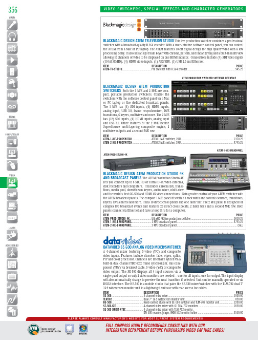
datavideo Se-500 analog video mixer/Switcher A 4-channel mixer featuring S-video (Y/C) and composite video inputs. Features include dissolve, fade, wipes, splits, PIP and color processor. Channels are internally synced via a ponent (YUV) via breakout cable, S-video (Y/C) or composite video output. The SE-500 displays all 4 input sources via asingle quad output so only 2 video monitors are needed – one for all inputs, one for output. The input display Blackmagic deSign atem televiSion Studio This live production switcher combines a professionaloduction pact, portable production switchers. Control the switchers with the software control panel via a Mac or PC laptop or the dedicated broadcast panels. The 1 M/E has (4) SDI inputs, (4) HDMI inputs, analog input, USB 3.0, frame resynchronizer, DVE transitions, 6 keyers, multiview and more. The 2 M/E has (12) SDI inputs, (4) HDMI inputs, analog input and USB 3.0. Other features of the 2 M/E include SuperSource multi-layering composite engine, 2 Blackmagic deSign atem Pr oduction Studio 4k The ATEM Production Studio 4K lets you connect up to 8 SD, HD or UltraHD 4K video cameras, tions, media pool, downstream keyers, audio mixer, multi-viewand the world’s first 6G-SDI and HDMI 4K video connections. Gain greater control of your ATEM switcher with atem-1-me-BroadPanelatem Production Switcher Software interfaceatem-Prod-Studio-4kFor expert advice - call: 800-356-5844M-F: 9:00-5:30 CentralDataViDeO Se-2000 HD-SDi This unit fea-tures 13 transitions with border, 5 indi-vidual speed keys (for instant selection with take effect), and the ability to insert up to 14 pre-stored logos. Includes 3 dedicated HD-SDI inputs, 1 DVI-D input andDataViDeO HS-2000 MObile ODuctiOn StuDiO/This unit features a 17" LCD monitor to display multiview out-puts, 1 DVI-D input, 3 HD-SDI inputs and 1 selectable DVI-D/HD-SDI input, a built-in 4-channel audio mixer, a 5-channel wired intercom with belt packs for camera ops. Monitor shows review input, program output, and picture-in-picture preview. Program output allows connection to external digital video recorder, which can be viewed on the unit’s screen. Also features luma key, built-in TBC and frame synchronizerson all inputs, and HD resolutions up to 1920x1080i DataViDeO Se-900 SD SwitcHeR SySteM This 8-input SD switch-er has an expand-able core feature set that includeschroma key cards and PIP. This2-piece switcher (control panel andrack mounted processor) is ideal for SD venues.The switcher accepts a mix of 8 input cards for DV, SDI,DVI, YUV and composite. Outputs include DV, SDI, composite,358Follow Us!inteliX HDMi/HDbaSet MatRiX SwitcHeRS Each output port allows the same signal to be routed to the HDMI connector and to a remote destination with an HDBaseT receiver. The HDBaseT ports support 1080p HDMI video with audio, bi-directional wide-band IR, HDCP, and matrix control via IR. Additional features include 2K resolution support, Deep Color, full 3D capabilities, control via IP, RS-232, IR, or front panel, and a full command set for RS232 and Ethernet control via 3rd party systems. Comes with an IR remote control that allows IR switching, IR eyes, and IR emitters.ITEM DE S CRIPTION PRICE DIGI-44B ........4 in/4 out HDMI/HDBaseT Matrix Switcher with 4 routing presets ........1764.00DIGI-88B ........8 in/8 out HDMI/HDBaseT Matrix Switcher with 8 routing presets ..............CALLinteliX FlX-8X8a MODulaR FleX MatRiX SySteM The FLX-8X8A is a card-based matrix distribution system, consisting of two input and two output slots. Insert any combination of HDMI, DVI, VGA, Y/Pb/Pr Component Video, and/or HDBaseT input cards with HDMI, DVI, and HDBaseT output cards. Use any input type with any output type. This matrix can drive both local and remote zone outputs via twisted-pair cabling. In addition to modules, the unit has built-in RS232 and ethernet connectors, front panel control, EDID management, and a 8x8 balanced stereo audio switcher for whole premise audio capabilities.ITEM DE S CRIPTION PRICE FLX-8X8A ..................8x8 flex matrix distribution system ...........................................4595.47FLX-HI4.....................4-port HDMI input card ...............................................................576.07FLX-DI4.....................4-port DVI input card ..................................................................576.07FLX-RI4.....................4-port RGB, YUV, SV, YC, CV scaling input card .......................1876.67FLX-BI4.....................4-port HDBaseT input card .......................................................1803.87FLX-HO4....................4-port HDMI output card .............................................................576.07FLX-DO4....................4-port DVI output card ................................................................576.07FLX-BO4....................4-port HDBaseT output card .....................................................1803.87Digi-88bPrices subject to change without notice. Call today or visit us online!HORita Kct-50cHaRacteR geneRatOR A stand-alone video charac-ter generator with built-in text editor, that works with a standard PC keyboard (no PC required) to superimpose captions and titles of up to nine lines of 20 characters each, on analog composite video. The horizontal and vertical size and position,black/white, mask on/off, and contrast for the characters is user adjustable. Date and time information can also be automatically inserted in a variety of formats. Up to 25 KCT-50s can be connected and controlled from a single PC keyboard.ITEM DE S CRIPTION PRICE KCT50........................Character generator ....................................................................379.28359A complete portable HD studio ina single unit. Single-person oper-ation of sound and picture using fad-ers, buttons and touch screen. Integratesan audio mixer, video switcher, multi-viewer touchscreen and USB video/audio streaming into a stand-alonedevice. Supports 12 input, 4-Channel video plus still channel for PanaSOnic aV-HS410 HD/SD SMaRt SwitcHeR This powerful, easy-to-usePanaSOnic ag-HMX100 Digital a/V MiXeR Integrating a HD/SD videoFORMat liVe HD/SD SwitcHeRThis half-rack unit-wide, 4:2:2 HD/SDing, built-in MultiViewer (4, 9, or 10images on a single display), chromakeyer, aux bus with an IP link toPanasonic's AWRP50 remote cameraLooking forvideoconverters?See pages364-368®gen10cOnVMaaS2360Follow Us!tV One S2 SwitcHeR/inPut eXPanSiOn MODuleS Any of the S2 Series can be used as standalone video and audio switcher or as expansion module for the C2 Scaler/Switcher Series. Only one S2 unit can be attached to a C2 product, but several S2 units can be daisy-chained to each other.ITEM DE S CRIPTION PRICE S2-101AA ..................1x2 audio power amplifier ...........................................................335.75S2-105CV ..................5x2 composite video switcher .....................................................250.75S2-105CVA ................5x2 composite video/audio switcher ...........................................335.75S2-105DVIA ...............5x1 DVI-D and stereo audio switcher ..........................................845.75S2-105PC ..................5x1 RGB/YPbPr switcher ..............................................................505.75S2-105PCA ................5x1 RGB/YPbPr switcher and stereo audio switcher ....................675.75S2-105YC ..................5x2 YC (S-Video) switcher ...........................................................250.75S2-105YCA ................5x2 YC (S-Video) and stereo audio switcher ...............................335.75S2-106AD ..................6x2 stereo audio switcher with full processing ...........................845.75S2-108HD ..................8x2 HD/SD-SDI routing switcher ................................................1440.75S2-109PC ..................9x1 RGB/YpbPr switcher ..............................................................675.75S2-110CV ..................10x2 composite video switcher ...................................................505.75S2-110YC ..................10x2 YC (S-Video) switcher .........................................................420.75S2-105PcaSOny McS-8M Multi-FOR Mat cOMPact SwitcHeR A multi-format switcher with a built-in audio mixer and a frame synchronizer. Features include preset DME wipe patterns, multi-viewer, keyer, 1-channel frame memory input, and a 3D Mode function. It operates in either HD or SD mode with the following inputs - (4) HD/SD-SDI, (3) HDMI (HD only), (3) analog composite (SD only) and (1) DVI-I. The 6-channel audio mixer has audio delay adjustment, a USB port and (2) XLR and (4) TRS outputs.ITEM DE S CRIPTION PRICE MCS-8M pact audio/video mixing switcher ............................................CALLOlanD V1600HD Ideal in live events or ing a high channel count and the ability to accept a variety of video input formats out of the box. All-in-one 14-channel (16-input) seamless switcher/mixer. Connect HS/SD-SDI x8, DVI-D x2, RGB x2, component x2,S-Video, and composite inputs. Also input still from a USB thumb drive. Output-3eX web 4-input video mixer with less switcher/mixer. input formats areOSS ViDeO cR OSSOVeR SOlO Multi-DeFinitiOn PR ODuctiOn SwitcHeR The CrossOver Solo is a powerful, all-in-one production switcher that fits small spaces and budgets. The main electronics and signal I/O are combined within the panel as a single unit. Features include a built-in multiviewer, input syn-chronization, (4) media store channels, chroma keyer, reference generator, robotic camera control and a rugged all metal construction. The unit has (10) source buttons, (12) HD-SDI inputs, (3) AUX bus outputs, (1) HD-SDI preview output and (2) HD-SDI program outputs.ITEM DE S CRIPTION PRICE CROSSOVER-SOLO .....All-in-one video switcher .................................................................CALLOur Sales Pros will provide you with the solutions you need.。
欧米加四通道手持数据记录温度计说明书

DISCONTINUEDDISCONTINUEDFour-Channel, Handheld Data Logger ThermometerWith USB InterfaceL-22U 4 Backlit Displays U R esolution 0.1°C/0.1°F, 1°C/1°F U F unctions: °C/°F/K, Max, Min, Avg, Hold, Rel,Limit, Hi/Lo, Type, Count, Time, Clock, Channel, T1-T2, T3-T4, Backlight, RS232, Rec, Call U N IST-Traceable Certificate of Calibration (No Points)U A uto Power-Off,Low Battery Indication U U SB Interface with Windows Software (Optional RS232 Cable Available)U 10,000 Record Data Logger U C ALL-Fit to Quick- Read Memory Data (50 Pages/Second)U P erpetual Calendar Function U C E-Mark Approval(Conforms to ITS-90)U B attery Life: 550 hr The OMEGA ®HH147U is a rugged, easy-to-use thermometer with4 standard miniature connector inputs. It accepts 7 different thermocouple types and displays all 4 inputs at the same time. It also provides differential temperature measurement readings of T3-T4, as well as individual readings of the 4 inputs. Other features are a low battery indicator, perpetual calendar, and auto power-off.SpecificationsThermocouple Range: Type K: -100 to 1300°C (-148 to 2372°F)Type J: -100 to 1000°C (-148 to 1832°F)Type E: -50 to 800°C (-58 to 1472°F)HH147UType T: -100 to 400°C (-148 to 752°F)Type R/S: 0 to 1700°C (32 to 3092°F)Type N: -100 to 1300°C(-148 to 2372°F)Accuracy (18 to 28°C Ambient):Type K/J/E/T:±(0.1% rdg + 0.7°C) -100 to 1300°C±(0.1% rdg + 1.4°F) -148 to 2372°F Type R/S: ±(0.1% rdg + 2°C) 0 to 1700°C±(0.1% rdg + 4°F) 32 to 3092°FType N:±(0.1% rdg + 1.5°C) -100 to 1300°C ±(0.1% rdg + 3°F) -148 to 2372°FOperating Temperature and Humidity: 0 to 50°C (32 to 122°F), 0 to 80% RH Storage Temperature and Humidity: -20 to 60°C (-4 to 140°F), 0 to 80% RH4 “AAA” batteries, software, USB cable and NIST certificate (no points), and operator’s manual.Ordering Examples: HH147U, data logger thermometer and SPHT-K-6, Type K generalpurpose surface probe. OCW-3, OMEGACARE SM extends standard 1-year warranty to a total of 4 years.These models include a free 1 m (40") Type Free Thermocouple Power Requirement:4 “AAA” batteries (included)Input Protection at Thermocouple Input: 4 Vac/Vdc maximumDimensions (Without Holster): 164 H x 76 W x 32 mm D (6.4 x 3 x 1.25")Weight: Approx 270 g (9.5 oz)No PointsO p t i o n al R S 232OMEGACARE SM extendedwarranty program is available for models shown on this page. Ask your sales representative for fulldetails when placing an order.OMEGACARE SM covers parts,labor and equivalent loaners.HH147U shown with SPHT-K-6, 6"Type K surface probe.。
- 1、下载文档前请自行甄别文档内容的完整性,平台不提供额外的编辑、内容补充、找答案等附加服务。
- 2、"仅部分预览"的文档,不可在线预览部分如存在完整性等问题,可反馈申请退款(可完整预览的文档不适用该条件!)。
- 3、如文档侵犯您的权益,请联系客服反馈,我们会尽快为您处理(人工客服工作时间:9:00-18:30)。
四通道功放说明书内装物品:必须保证下面所示所有附件全都提供并未被损坏。
整机说明手册保修卡合格证非常感谢您对产品的信赖。
为了您更好的使用产品,请详细阅读说明书,以便获得最理想的使用效果。
警告:为防止火灾或触电危险,切勿将本设备放置雨淋或潮湿环境中。
使用安全●电源:本装置只能使用说明上所标注的电源种类。
●电源线保护:要注意电源线不要被重物压挤,特别要注意电源线的插头。
装置上的出线处及方便插座处,切忌拉、抽电源线,不要把电源设在人员来往频繁的地方,以免造成因插头破损而发生触电或火灾事故。
●通风:本装置必须置于通风良好的场所,离墙距离不能小于10CM,不要将本装置置于床上、沙发、地毯,或类似的东西的表面上使用,以免拦住通风口。
●水/湿气:不能在离水很近的地方使用,例如:浴缸、洗漱池、洗手盆、潮湿的地下室及游泳池附近等使用。
●温度:本装置必须远离热源。
例如:散热器、加热电阻、各种炉子及其他发热装置等。
●电击:必须防止物品或水掉进机内。
如果掉进金属或其他导电物品,会使装置内部产生电击短路的。
●清洁:不要使用腐蚀性溶液,避免损坏设备。
●异常气味:当发现有异常气味或冒烟等现象,应立即切断电源并拔出逝者插头,与供货商或最近的维修部门联系、寻求维修服务。
●长期闲置时:为安全起见,请切断电源开头,拔掉电源插头,以防火灾发生。
●安全接地:本产品通过电源线的接地导线接地,为了避免电击,为了您和他人的人身安全,使用过程,请将产品可靠接地。
注意:因机内存有高压,非电子专业人员切勿白拆卸机壳,如果内部电子零件被非正常接触,可能发生严重电击事故。
若发生此类事故,本公司概不负责。
1机身高度 Height Of Frame 2RU生产工艺 Manufacturing Processes SMD频率响应Frequency Response : 20 Hz –20 kHz总谐波失真THD <0.05%信噪比Signal To Noise Ratio >80 dB阻尼系数Damping Coefficient>200 >200分离度Degree Of Separation >60 dB转换速率Slew Rate >12V/μs输入灵敏度Input Sensitivity 0.775Vrms输入阻抗(不平衡/平衡) Input Impedance(Unbalance/Balance) 10kΩ/20 kΩ电压增益(8Ω时)V oltage Gain( @8 Ω) 834.3dB 36.0dB功放拓扑类别Output Circuit Type 3-tier Class H风路从后板吸风向前后吹The air flow is from the rear panel to the front panel面板介绍Voltage Switch On/Off背板介绍:Air Vent3Ch1 Ch2立体声与桥接开关Limiter Switch简介:Brief Introdution●非常感谢您购买本公司的音频功率放大器。
请阅读以下说明、以获得产品的最佳效果:特点驱动能力:●每个通道驱动20hm负载时,允许工作于峰值因数(CF)大于4的信号。
●每个通道驱动40hm或40hm以上负载时,允许工作于峰值因数(CF)大于2.83的信号。
保护系统:Protecting System●温度控制电路检测功率晶体与变压器温度,温度变化时连续调整散热风扇气流速度,以期降低系统温度。
The temperature of the transistor and the transformer will be controlled. With the change of the temperature, it will adjust the flow rate for the cooling fans to reduce the temperature of the system.●开机软启动。
Soft Starting●短路保护。
Short-Cut Protection●过载保护。
Overload Protection●直流输出保护。
DC output Protection●失真限幅。
Distortion Limiter●开机音量渐大。
The V olume is greater when power on●过热保护。
Over-heat Protection性能:●极高的转换速率>12V/μs,以期获得清晰锐厉的高频能Performance:Very high slew rate >12V/μs, to get the clear and high frequency power.●极高的阻尼系数阻尼系数>200 >200,以期获得完美的低频控制力。
High dumping coefficient>200 >200, to get the perfect low frequency controlling.●极高的信噪比信噪比>80 dB。
High signal to noise ratio >80 dB。
4功能:Fuction●前面板设置输出信号,过载或故障LED,电源指示灯。
With the input signal on the front panel, LED of over load or fault, power on/off indicator.●XLR平衡接头输入,Speakon和60A防碰保护接线柱式扬声器连接。
XLR balance input, Speakon and 60A anticollision protection binding post speaker connection●后面板设置可恢复的电源过载保护器The rear panel setting with the recovered power over loading protector●电源开机浪涌电流限位,无需进行电源时序控制。
The power switch on/off is no need the power sequence controller.重要的安全注意事项和符号说明1、请仔细阅读用户手册。
2、请保存好用户手册。
3、请注意所有警告。
4、请遵守这些规定。
5、请用于布擦拭。
6、请不要堵塞通风口。
7、请不要安装在会产生热量的设备附近,如散热器、热调节装置、炉子、散热风向与本机相反的设备。
8、请经常检查插头电极或接地的安全性。
如果插头已老化损坏或和您的插座不匹配,请向电工咨询了解如何更换该旧插座。
9、请注意保护电线,请勿踩踏或挤压。
10、请使用本公司指定的附件或配件。
11、在雷电发生期间或长时间不用时,请拔下本设备的插头。
12、如果本设备损坏,必须进行维修,请交由公司指定的合格人员进行维护。
等边三角形内的惊叹号是提醒用户本手册中重要的操作和维护(维修)说明。
为避免电击危险,请不要移除盖板。
内部无用户能维修的零件。
请联络合格专业人士进过维修。
闪电符号,警告用户有非绝缘“危险”电压,会对人体产生电击危险。
为避免着火或电击,请不要将设备暴露于雨中或潮湿环境中。
不要在靠近水的地方使用本设备。
放大器输出端旁边的闪电符号警告用户输出端子有触电危险。
放大器电源打开时切勿接触输出端子。
有可能造成危险的输出连接器都标有闪电符号。
注意:干扰声明本设备已经测试符合国家标准GB13863,GB13837,GB17625等限制。
所规定的这些限制是为了提供合理的保护,防止对住宅设拖造成有害干扰。
此设备会产生、使用和发出无线电频率能量,如果不按照指导进行安装和使用,可能会对无线通信造成有害干扰。
但是,我们不排除在特定安装条件下仍会产生干扰的可能性。
如果本设备对无线电或电视接收造成了有害干扰(通过关闭后再打开设备即可以确定),建议用户尝试5采取以下一项或多项措施来排除此类干扰:●变换接收天线的朝向或重新放置。
●增大设备和接收器之间的距离。
●将设备使用的电源插座与接收器所使用的插座分开。
●咨询经销商或有经验的无线电或电视技术人员寻求帮助。
性能规格本公司设计的各系列型号放大器在线路设计与器件选择上有相同的高要求,因此它们能达到一样的高性能参数,它们中是功率不同而已。
总谐波失真THD:正常工作条件,1KHz <0.05% 互调失真Intermodulation Distortion:正常工作条件,60Hz/7KHz-4/1 < 0.075% 频率响应Frequency Response:正常工作条件,20Hz-20KHz < +/-0.25dB 功率带宽Power Band Wide:正常工作,-3dB 10Hz-50KHz 相位响应Phase Response:正常工作条件,20Hz-20KHz < +/-8度信噪比Signal To Nosie Ratio:1KHz,1V输入,A计权>110dB 阻尼系数Dumping Coefficient:正常工作条件,63Hz >1500 转换速率Slew Rate:10KHz方波,40dB增益Gain >100V/us 输入阻抗Input Impedance:正常工作条件,(不平衡/平衡) 10kΩ/20 kΩ0hm 分离度Degree Of Separation:1KHz,0.775输入Input >80dB共模抑制Common Mode Restrain:正常工作条件,1KHz >80dB Measurement(cbm)/产品外形尺寸(宽x深x高)483x395x89mm外包装尺寸(宽x深x高)595x565x170mm重量:4*600W 4*450W 4*350W 4*250W机身重量N.W.(kgs)25kg 24kg 23kg 22kg总重量C.W.(kgs)27kg 26kg 25kg 24kg注释峰值因数(CF)控制-峰值因数:信号波形的电压峰值与电压有效值之比。
-峰值功率:放大器短时间输出的最大功率,注意此数值一定不可大于扬声器额定难承受的峰值功率,否则易造成扬声器的机械损坏。
-最大不失真功率:输入一个规定的正弦信号,在允许的失真范围内,放大器能够输出的最大的有效功率。
-有效值功率:在一个规定的时间段里,放大器输出的能量总和与时间的比值,这个参数能够真正反应放大器传输给扬声器的平均功率,注意此数值一定不可大于扬声额定能长期承受的功率,否则易造成扬声器的过热损坏。
-峰值因数高的信号压缩少,音质好,峰值因数低于2.8时音质已劣化到无法使用。
6-峰值因数为4的信号有效功率大的是最大不失真功率的1/8,峰值因数越低则放大器发热越多,扬声器更容易损坏。