谐波减速器柔轮力学特性分析
基于ABAQUS采用二分法分析优化谐波减速器柔轮

的 响 应 比 中 间转 子 的 响 应 更 显 著 ,且 各 对 齿 轮 的 动 态
啮合力 也较 大 。 严格 控制输 入转子 的动平 衡 , 改善 故 对 功 率双 分支 齿 轮传 动系 统 的振动 性 能很重 要 。
收 稿 日期 :0 1 1 月 21年 1
转 子 4上 存 ຫໍສະໝຸດ 同 等 大 小 不 平 衡 激 励 时 . 各 个 齿 轮 之 间
的动态 啮合 力 较小 。
1 0 9,1 93. 91 7 9
[ ] K at T L A Me o o A a z n pi z h J d 3 rnz . t dt nl e ad O t e te I a h y mi 0 S aigo piP t Tas si s[ . A A T 0 2 1 h r f l a rnmi o n S t h s n R] N S M 17 0 ,
[ ] 夏 伯 乾 , 烈 , 友 柏 .H 型 压 缩 机 齿 轮 一 承一 子 系 统 6 虞 谢 D 轴 转 动力 学 分 析 [] 动 工程 学 报 ,0 2 1 2 : 1 2 5 J. 振 2 0 , 6( ) 5 — 5 . 2
[ ] Ka t TL R sii Ks . piT ru rnmsi 7 rnz , ahd M, i JG S l oqeTas i o h t sn l a hr g[ . A A T 0 8 419 . o dS ai R] N S M 15 8 , 2 n 9
19 . 9 6
3 结 论
1 )功 率 双 分 支 齿 轮 传 动 系 统 的 振 型 多 表 现 为 多 转 子 的 弯 扭 耦 合 振 动 ,应 按 照 齿 轮 耦 合 转 子 动 力 学 进 行 功率 双分 支齿 轮 传动 系统 的 动力学 设 计 。 2)双 分 支 齿 轮 传 动 系 统 存 在 功 率 分 流 和 汇 流 , 当 输 入 转 子 或 输 出转 子 上 存 在 不 平 衡 激 励 时 .齿 轮 的 耦 合 效 应 明 显 。 人 转 子 上 存 在 不 平 衡 激 励 时 , 出 转 子 输 输
谐波减速器柔轮的有限元分析

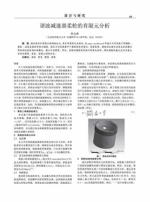
设计与研究49谐波减速器柔轮的有限元分析徐志鹏(北京航空航天大学交通科学与工程学院,北京100191)摘要:通过理论计算得出齿间喷合力,并采用有限元分析法,在ansys-workbench中建立不同负载下的钢轮- 柔轮-波发生器的有限元模型,得出不同负载条件下柔轮的变形情况。
结果表明,柔轮的主要变形发生在齿圈与 筒体的过渡区域和齿圈处。
建立不同壁厚、筒长、齿宽的柔轮对其进行有限元分析,得出柔轮的最大应力与最大 变形与壁厚、筒长、齿宽之间的关系。
关键词:柔轮筒长壁厚齿宽引言在工业高速发展的趋势下,体积小、传动比高、传动 效率大的谐波减速器,应用地越来越广泛。
谐波减速器主 要由固定的内齿圈刚轮、可发生大变形的薄壁柔轮和主动 输入的凸轮波发生器三个核心部件组成。
谐波传动过程中,波发生器会使柔轮轮齿在最大变形区域与刚轮轮齿完全啮 合,并在最小变形区域与刚轮完全脱离。
为保证这种特殊 的啮合方式,柔轮必须能产生较大的径向变形。
薄壁柔轮 在谐波传动中决定谐波减速器的寿命,因此对于柔轮的应 力和结构研宄成为焦点问题[1]。
目前,国内的谐波减速器 与日本、美国等国家的谐波减速器相比,在相同功率情况下,国内谐波减速器尺寸大、承载能力小,难以满足国内工业 发展的需求。
因此,对谐波减速器柔轮的承载能力与结构 尺寸进行分析具有重要意义。
1柔轮三维模型的建立本文建立的谐波减速器型号为XB1-80。
柔轮的主要技术参数:模数m=0.5,柔轮齿数21=160,轮齿压力角(1。
=20°,齿顶高系数ha*=0.5,齿根高系数c*=0. 15。
利用 三维设计软件soildworks,可快速建立谐波减速器的三维 实体模型,并可通过基本参数模型迅速重建新的模型,从 而提高建模计算效率。
2柔轮的有限元分析2.1前处理本文不对谐波减速器柔轮的轮齿进行应力分析,若柔 轮采用全齿模型进行计算,网格划分将非常复杂,得不到 较好的网格质量。
谐波减速器柔轮与柔性轴承断裂失效分析

2023年第47卷第3期Journal of Mechanical Transmission谐波减速器柔轮与柔性轴承断裂失效分析穆晓彪1邵洙浩2郝春辉1高明艳1张朝磊2(1 北京中技克美谐波传动股份有限公司,北京101300)(2 北京科技大学材料科学与工程学院,北京100083)摘要通过观察显微组织、测定力学性能以及观察断口形貌,对比分析国产失效谐波减速器和日本谐波减速器关重件柔轮和柔性轴承的显微组织和力学性能,并分析了国产谐波减速器过早失效的原因。
结果表明,失效谐波减速器柔轮显微组织与日本相同,均为回火屈氏体,失效柔轮平均晶粒尺寸为8.2 μm,比日本柔轮平均晶粒尺寸高了1.5 μm;失效柔性轴承和日本柔性轴承显微组织均为回火马氏体,失效柔性轴承平均晶粒尺寸为13.1 μm,比日本柔性轴承平均晶粒尺寸高出6.9 μm。
失效谐波减速器柔轮断口呈脆性断裂,无明显裂纹源,但失效的柔性轴承断口存在明显断裂走向,在裂纹源中有大尺寸、聚集性分布的夹杂物。
失效轴承钢质洁净度差,存在大尺寸夹杂物,且显微组织晶粒粗大,阻碍裂纹扩展的能力差,导致国产谐波减速器过早失效。
关键词柔轮柔性轴承晶粒尺寸夹杂物Fracture Analysis on Flexspline and Flexible Bearing of the Harmonic Reducer Mu Xiaobiao1Shao Zhuhao2Hao Chunhui1Gao Mingyan1Zhang Chaolei2(1 Beijing CTKM Harmonic Drive Co., Ltd., Beijing 101300, China)(2 School of Materials Science and Engineering, University of Science and Technology Beijing, Beijing 100083, China)Abstract Microstructure and mechanical properties of the failure flexspline and the Japanese flexspline for harmonic reducers and fracture reason are analyzed by quantitative of microstructure, determination of me⁃chanical properties and fracture analysis. The result shows that the microstructure of the flexspline of the failed harmonic reducer is the same as that of Japan, both of which are tempered troostite. The average grain size of the failure flexspline is 8.2 μm, which is 1.5 μm higher than that of the Japanese flexspline. The microstructure of the failure and Japanese flexible bearings is tempered martensite. The average grain size of failure flexible bearings is 13.1 μm, which is 6.9 μm higher than that of the Japanese flexible bearings. The fracture morpholo⁃gy of the flexspline presents brittle fracture characteristics without obvious crack source. The fracture of flexible bearings shows obvious fracture trend. There are obvious crack trends in the fracture of flexible bearing. The crack source is pinpointed at the region where large agglomerative inclusions are observed. The poor purity of flexible bearing and the coarse microstructure with poor ability to hinder crack propagation are the main causes of premature failures of domestic harmonic reducers.Key words Flexspline Flexible bearing Grain size Inclusion0 引言谐波减速器由柔轮、刚轮、柔性轴承和凸轮轴组成,是基于弹性薄壳弹性变形理论、应用金属挠性和弹性力学原理发展起来的一种减速器。
谐波减速器柔轮力学特性分析

IV
目
录
目
录
中文摘要..........................................................................................................................................I 英文摘要....................................................................................................................................... III 1 绪 论......................................................................................................................................... 1
III
重庆大学硕士学位论文
area is improved markedly after the structure optimization design. ④First of all, this thesis carries on a finite element analysis of flexsplines’ torsional rigidity between two harmonic reducer with different structure parameter and acquires the flexspline’s torsional rigidity. Then the author designs and establishes a harmonic reducer’s torsional rigidity test system. Through the analysis of the test data, the author gets the torsional rigidity of harmonic reducer. The experimental reusults show that the torsional rigidity of Model One with optimized structure parameter is higher than that of Model Two without optimized structure parameter. At the same time by comparing the results of finite element analysis, we find that both of their harmonic reducers’ torsional rigidity show the consistency. That is to say, the optimization of structure parameter can help to improve the torsional rigidity of harmonic reducer. Key Words: harmonic reducer; flexspline; mechanical characteristics; finite element analysis; torsiona论文
谐波减速器柔轮力学特性分析

College of Mechanical Engineering of Chongqing University, Chongqing, China May 2015
中文摘要
摘
要
谐波减速器是一种利用可控变形的柔性构件产生的变形波进行运动或动力传 递的新型传动装置,由于其具有其他传动装置所难以达到的特殊性能,因此在航 天装备和机器人领域得到越来越广泛的应用。但是,工程实践表明,谐波减速器 平均无故障工作的时间较短, 其最突出的问题是柔轮的可靠性、 使用寿命不理想, 输出端扭转刚度不足。作为谐波减速器主要构件的柔轮是一个薄壁壳体,受波发 生器和外部负载的双重作用,在循环弹性变形的状态下工作,既承受弯曲应力, 又承受扭转应力,很容易发生疲劳失效。因此,对谐波减速器的柔轮进行力学特 性方面的分析有着重要的意义。 本文以谐波减速器的柔轮为主要研究对象,完成了下列工作: ①介绍了谐波减速器的工作原理、传动特点及应用领域,对柔轮在波发生器 作用下的变形、应力和疲劳强度进行了理论计算。 ②根据课题要求,设计了一种传动比为 100 的谐波减速器,利用有限元分析 软件 ANSYS Workbench 建立了柔轮——波发生器有限元非线性接触模型,分析了 柔轮在波发生器作用下的变形规律和应力分布,结果表明柔轮齿圈与光滑筒体连 接处和光滑筒体与筒体底部过渡处为柔轮的应力危险区域。 ③分析了柔轮在不同长径比和不同壁厚参数下的变形规律和应力分布。然后 对柔轮应力危险区域进行结构参数调整和优化设计,建立了有限元非线性接触模 型,重点分析了柔轮的应力分布情况,结果表明经过对结构参数的优化设计,柔 轮应力危险区域的应力分布得到明显改善。 ④首先对两种不同结构参数的谐波减速器柔轮进行了扭转刚度有限元分析, 得到了柔轮的扭转刚度,然后设计并搭建了一套谐波减速器扭转刚度测试系统, 通过对测试数据的分析得到了它们的扭转刚度。测试结果表明经过结构参数优化 的机型一的扭转刚度比未经结构参数优化的机型二扭转刚度要高得多,同时通过 对照有限元分析的结果,两者得到的谐波减速器的扭转刚度呈现出一致性,表明 了结构参数的优化有利于提高谐波减速器的扭转刚度。 关键词:谐波减速器,柔轮,力学特性,有限元分析,扭转刚度
谐波传动柔轮变形测量误差分析与补偿

sation;wave generator
引言 1
测量误差分析 2
谐 波 减 速 器 依 靠 中 间 柔 性 部 件(柔 轮)周 期 性 弹 性 变 形 来 实 现 运 动 及 动 力 传 递 ,当 波 发 生 器 装 配 进 入 柔 轮 后 ,柔 轮 在 波 发 生 器 作 用 下 产 生 一 定 程 度 的 弹 性 变 形 ,使 得 柔 轮 齿 与 刚 轮 齿 进 行 啮 合 。 [1-2] 但在传动过程中,柔轮齿圈上每个位置的 变 形 是 动 态 变 换 ,会 一 定 程 度 上 影 响 齿 轮 产 生 啮 合 干 涉 或 者 脱 离 啮 合 。 一 般 为 了 便 于 计 算 ,理 论 上 将 柔 轮 中 性 层 的 形 变 近 似 作 为 柔 轮 的 变 形 ,但 柔 轮 在 实 际 的 弹 性 变 形 是 十 分 复 杂 的 ,实 际 测 量 柔 轮 ቤተ መጻሕፍቲ ባይዱ 形 函 数 与 理 论 位 置 存 在 较 大 差 异[3-5],因 此 精确测量柔轮在波发生器作用下的实际径向变 形规律成为当前研究重点。
(1. 北京工业大学 先进制造技术北京市重点实验室,北京 100124; 2. 江苏科技大学机械工程学院,江苏 镇江 212003)
摘 要 :波 发 生 器 安 装 误 差 是 柔 轮 变 形 测 量 中 较 为 常 见 的 误 差 来 源 之 一 ,安 装 误 差 的 存 在 使 得 柔 轮 变 形 与 转 动 角 度 之 间 的 函 数 关 系 产 生 较 大 偏 差 。 为 解 决 波 发 生 器 中 心 与 回 转 中 心 的 安 装 误 差 问 题 ,本 文 对 柔 轮 测 量 误 差 进 行 分 析 ,并 提 出 柔 轮 径 向 变 形 误 差 补 偿 方 法 。 首 先 ,基 于 坐 标 变 化 原 理 建 立 了 偏 心 误 差 表 征 数 学 模 型 ,获 得 安 装 偏 心 量 、波 发 生 器 实 际 结 构 参 数 ;其 次 ,基 于 波 发 生 器 偏 心 径 向 变 形 函 数 构 建 了 柔 轮 径 向 变 形 误 差 修 正 模 型 ,对 安 装 偏 心 工 况 下 柔 轮 实 际 径 向 变 形 函数进行修正补偿。实验结果表明:在安装误差影响下柔轮变形函数峰谷偏差达 0. 134 mm,与理论相差较大;通过本文 方法进行修正补偿后,误差在 0. 012 mm 左右,且柔轮径向变形结果与理论变化趋势基本一致。该方法能够有效提高柔 轮 径 向 变 形 测 量 精 度 ,为 优 化 谐 波 减 速 器 的 齿 廓 参 数 奠 定 实 验 与 理 论 基 础 。 关 键 词:谐波减速器;柔轮径向变形;安装偏心;误差补偿;波发生器 中图分类号:TD632. 1 文献标识码:A doi:10. 37188/OPE. 20212904. 0793
谐波传动柔轮应力与位移二维简化分析
【 上接第1 2 】 2页
此 同时 ,齿 顶 及 齿 面 方 向应 力 值 较 小 。 由于 有 柔 性 轴 承 模 型 在 长 轴 方 向为 单 个 滚 动 体 接 触 ,受力
不 均 匀 ,所 以 齿 根 最 大 应 力 值 稍 大 ,为 1 3 a 2 Mp ; 无 柔 性 轴 承 模 型 凸轮 与 柔 轮 接 触 ,受 力 均 匀 ,齿 根 最大 应 力值 稍 小 ,为 13 a 总体 而 言 ,两组 1Mp 。 模型 柔轮 齿根 应力 相差 不大 ,数值 近似 相等 。
摘 要 :利用有限元软件A A U 分别建立 了有柔性轴承以及无柔性轴承的谐波传动平面简化 模型 , BQS 对 装配完成后柔轮应力及径向位移进行了分析。结果表明 ,无柔性轴承的谐波传动模型相 对于有 柔性轴承模型不仅柔轮应力及径向位移分布相同 ,数值近似相等 ,而且计算 效率较高 , 在使用 有限元方法分析柔轮强度时完全可以代替有柔性轴承的谐波传动模型。上述 结果 对谐 波齿 轮传 动有限元建模有一定的指导作用 。 关键词 : 谐波传动 ;AB Q S;桑性轴承 ;应力 ;径向位移 AU
0 引言
谐波齿轮传动 是二十世 纪 5 0年 代 末 和 6 0年 代初 问世 的一种 崭 新传 动 Ⅲ。它 与一般 齿 轮传 动相 比 ,具 有传 动 比 大 、体 积 小 、重 量 轻 、精 度 高 及
噪 声 小 等 优 点 。近 几 十 年 来 ,谐 波 齿 轮 传 动 技 术
E 20 a = 1Gp ,泊松 比 03 . 。
中图分类号 :T 1 24 H .3 3 文献标识码 :A 文章编号 :1 0 - 1 4 2 1 ) ( -0 1 0 9 0 ( 0 2 1 上) 1 - 3 0 3 0 2
具有复合层结构的谐波减速器柔轮的性能优化设计研究
9 6
第 2期
2 0 1 4年 2月
Ma c h i n e r y De s i g n
&
Ma n u f a c t u r e
具有复合层 结构的谐波减速 器柔轮 的性能优化设计研 究
邱建喜 , 杨 为, 段成财
( 重庆大学 机械传动 国家重点实验室 , 重庆 4 0 0 0 3 0 )
m a x i m u m V o n Mi s e s s t r e s s o n t h e l f e x s p l i n e w i t h c o m p o s i t e i s r e d u c e d n e a r l y 1 2 . 5 %. nd a t h e m xi a m l a s t r e s s p o s i t i o n a l s o i s
fc o o m p si a t e l a y e r . he T o p t i m i z e d ma t h e m a t i c l a m o d e l i s p r o p o s e d , w h i c h p l y a n g l e a n d s t ck a i n g s e q u e n c e re a c o n s i d e r e d s a o p t i mi z ti a o n v ri a a b l e s , nd a T s a i — Wu f a i l u r e c r i t e r i o n i s c o n s i d e r e d s a c o n s t r a i n t c o n d i t i o n , a n d m i n i mu m s t r e s s i n s i n g l e l a y e r i s c o n s i d e r e d s a o p t i mi z ti a o n o b j e c t i v e . he T o p t i m l a r e s u h s fp o a ng l e a n d s t ck a i n g s e q u e n c e re a o b t in a e d u s i n g p rt a i c l e s w rm a l a g o r i t h m . T r a si n e n t d y n a m i c s na a l y s i s f o t h e o p t i mi z e d h rm a o n i c d r i v e r e d u c e r s i s ch a i e v e d. he T r e s u l t s re a s h o w n ,
基于ANSYS的谐波减速器柔轮受力分析解读
基于ANSYS的谐波减速器柔轮受力分析本文以典型的谐波齿轮传动系统的柔轮为研究对象,介绍了谐波齿轮传动的发展历史、特点及其工作原理,利用UGNX4.0参数化方法建立了不同长径比和不同壁厚的柔轮实体模型,并利用APDL方法建立柔轮不同长径比、不同壁厚和不同载荷下的有限元模型。
利用ANSYS10.0的接触分析技术在波发生器与柔轮之间建立两对面-面接触模拟边界条件和初始载荷,对柔轮在不同载荷下以及不同长径比和不同壁厚的柔轮在特定负载时的应力分布和变形进行了了分析计算,得出了柔轮应力分布规律和柔轮变形规律。
本文在建立有限元模型时在结构上采用了完整模型,而且保留柔轮轮齿,借助ANSYS三维立体单元SOLID185、接触单元TARGE170和CONTA174本身的算法。
故本文处理方法下的计算结果更接近真实情况,为柔轮结构的优化提供了有用的数据。
同主题文章[1].邓祥明,孔凡国. 谐波齿轮传动多目标优化设计' [J]. 机械设计与研究. 1998.(02)[2].董惠敏,刘书海. 谐波齿轮传动多目标模糊优化设计的研究' [J]. 机械传动. 2003.(02)[3].龙东平,谭建平,周亮. 大型粉料储罐系统有限元分析' [J]. 建筑机械. 2005.(10)[4].严国平,刘正林,朱汉华,费国标. 大型船用斜齿轮参数化建模及其接触有限元分析' [J]. 武汉理工大学学报(交通科学与工程版). 2007.(02)[5].崔博文,沈允文. 谐波齿轮传动的接触状态分析及侧隙计算' [J]. 机械科学与技术. 1996.(04)[6].辛洪兵,何惠阳,张承嘉,谢金瑞. 四齿差谐波齿轮传动精度特征的试验研究' [J]. 机械科学与技术. 2001.(04)[7].郭振旺,姚辉,陈志忠,王宇业. 柴油机曲轴强度的三维有限元分析' [J]. 柴油机. 2005.(03)[8].赵汝嘉,陆还珠,黎德龄,褚启勤. 机床大件动、静特性有限元分析——板、梁组合结构子结构分析法' [J]. 西安交通大学学报. 1980.(02)[9].程光蕴,郑自钧,吴克坚. 盒式录音机按键机构的受力分析' [J]. 机械科学与技术. 1985.(02)[10].李玉光,尤竹平. 谐波齿轮传动柔轮位移场和应力场的有限元分析' [J]. 大连大学学报. 1991.(04)【关键词相关文档搜索】:车辆工程; 柔轮; 谐波齿轮传动; 有限元; 接触; 受力分析【作者相关信息搜索】:上海交通大学;车辆工程;何维廉;张世民;。
谐波齿轮传动柔轮的变形分析
谐波齿轮传动柔轮的变形分析祝海林;蒋宇;王铖龙;钱志达;宁鹏【摘要】柔轮是谐波齿轮传动装置的主要部件,柔轮的变形直接影响柔轮的应力、寿命及谐波齿轮传动机构工作的可靠性.本文通过理论推导,建立了双波谐波齿轮传动环形柔轮变形量、截面弯矩的计算模型,提出了柔轮变形敏感度的概念,并对柔轮变形的敏感度与中性层曲率半径变化进行了仿真,得出了柔轮齿数的合理取值范围及柔轮圆环危险截面的位置,可为柔轮的性能分析、改进设计提供参考.%Flexible gear is the chief part in harmonic gear drive. The deformation of flexible gear affects directly the stress, worklife of Flexible gear and the reliability of harmonic gear drive. In this paper, the computation model for deformation and cross - section moment on ring-flexspline of two-wave harmonic gear drive is established theoretically. A concept of deformation sensitivity on flexible gear is put forward. Reasonable value for gear-number and the location for critical section of ring-flexspline are concluded based on the simulative analysis about deformation sensitivity and curvature radius of neutral layer for ring-flexspline, which is for reference to analyze the features and then to improve or redesign on current used flexspline.【期刊名称】《制造技术与机床》【年(卷),期】2013(000)003【总页数】5页(P150-154)【关键词】谐波齿轮传动;柔轮;中性层;变形敏感度;危险截面【作者】祝海林;蒋宇;王铖龙;钱志达;宁鹏【作者单位】常州大学机械工程学院,江苏常州 213016【正文语种】中文【中图分类】TH132.43谐波齿轮传动是上世纪50年代后期为适应空间科学、宇航尖端技术的发展而出现的一种新型传动技术,它具有结构简单、传动比大、承载能力高、齿面相对滑动速度低、传动平稳、噪声小等优点[1],所以在航天航空、仿生技术、原子反应堆、机床、仪器仪表、机器人、汽车、常规武器、印刷机构及医学器械等领域得到了广泛应用[1-2]。
- 1、下载文档前请自行甄别文档内容的完整性,平台不提供额外的编辑、内容补充、找答案等附加服务。
- 2、"仅部分预览"的文档,不可在线预览部分如存在完整性等问题,可反馈申请退款(可完整预览的文档不适用该条件!)。
- 3、如文档侵犯您的权益,请联系客服反馈,我们会尽快为您处理(人工客服工作时间:9:00-18:30)。
A Thesis Submitted to Chongqing University in Partial Fulfillment of the Requirement for the Professional Degree
By Xie.Hengpeng
Supervised by Prof. Wang Jiaxu Specialty: ME(Mechanical Engineering Field)
College of Mechanical Engineering of Chongqing University, Chongqing, China May 2015
中文摘要
摘
要
谐波减速器是一种利用可控变形的柔性构件产生的变形波进行运动或动力传 递的新型传动装置,由于其具有其他传动装置所难以达到的特殊性能,因此在航 天装备和机器人领域得到越来越广泛的应用。但是,工程实践表明,谐波减速器 平均无故障工作的时间较短, 其最突出的问题是柔轮的可靠性、 使用寿命不理想, 输出端扭转刚度不足。作为谐波减速器主要构件的柔轮是一个薄壁壳体,受波发 生器和外部负载的双重作用,在循环弹性变形的状态下工作,既承受弯曲应力, 又承受扭转应力,很容易发生疲劳失效。因此,对谐波减速器的柔轮进行力学特 性方面的分析有着重要的意义。 本文以谐波减速器的柔轮为主要研究对象,完成了下列工作: ①介绍了谐波减速器的工作原理、传动特点及应用领域,对柔轮在波发生器 作用下的变形、应力和疲劳强度进行了理论计算。 ②根据课题要求,设计了一种传动比为 100 的谐波减速器,利用有限元分析 软件 ANSYS Workbench 建立了柔轮——波发生器有限元非线性接触模型,分析了 柔轮在波发生器作用下的变形规律和应力分布,结果表明柔轮齿圈与光滑筒体连 接处和光滑筒体与筒体底部过渡处为柔轮的应力危险区域。 ③分析了柔轮在不同长径比和不同壁厚参数下的变形规律和应力分布。然后 对柔轮应力危险区域进行结构参数调整和优化设计,建立了有限元非线性接触模 型,重点分析了柔轮的应力分布情况,结果表明经过对结构参数的优化设计,柔 轮应力危险区域的应力分布得到明显改善。 ④首先对两种不同结构参数的谐波减速器柔轮进行了扭转刚度有限元分析, 得到了柔轮的扭转刚度,然后设计并搭建了一套谐波减速器扭转刚度测试系统, 通过对测试数据的分析得到了它们的扭转刚度。测试结果表明经过结构参数优化 的机型一的扭转刚度比未经结构参数优化的机型二扭转刚度要高得多,同时通过 对照有限元分析的结果,两者得到的谐波减速器的扭转刚度呈现出一致性,表明 了结构参数的优化有利于提高谐波减速器的扭转刚度。 关键词:谐波减速器,柔轮,力学特性,有限元分析,扭转刚度
IVห้องสมุดไป่ตู้
目
录
目
录
中文摘要..........................................................................................................................................I 英文摘要....................................................................................................................................... III 1 绪 论......................................................................................................................................... 1
I
重庆大学硕士学位论文
II
英文摘要
ABSTRACT
Harmonic Reducer is a new type of gearing transmission which using elastic deformation wave generated by flexible thin-wall components to transmit power. Compared to traditional gearing transmission, it is a kind of gearing transmission with smaller volume, lighter quality, higher transmission ratio and transmission accuracy. Therefore, it is applied more and more extensively in the field of space mechanism and industrial robots. However, engineering practice indicates that harmonic reducer’s average trouble-free working time is shorter, the most prominent problem is that its flexspline’s reliability and service life is not ideal, the output rigidity of the whole machine is stiffness. As the main component of harmonic reducer, flexspline is a thin-shell and it will suffer alternating bending stress as well as torsional stress under the working state of repeated elastic deformation, so fatigue fracture will happen easily. In view of this, it is of important significance to analyze the mechanical characteristics of harmonic reducer’s flexspline. This thesis takes the harmonic reducer’s flexspline as its research object and finished the following work: ①Introducing the working principle, transmission characteristics and application fields of harmonic reducer as well as the theoretical formula deduction of deformation, stress and fatigue strength of flexspline. ②According to the project requirement, this thesis designs a harmonic flexspline with 100 reduction ratio, establishes a finite element nonlinear contact model of flexspline and wave generator based on finite element analysis software ANSYS Workbench. This thesis also analyze the deformation and distribution of stress of flexspline under the action of wave generator, it turns out that the junction of flexspline’s gear ring and its smooth cylinder as well as the transition of smooth cylinder and its bottom can be taken as the stress dangerous areas for flexspline. ③Analyzing the effect of different length to diameter ratios and different wall thickness parameters on the influence of flexspline’s deformation and stress distribution. Then, the author takes structure optimization design for flexspline’s stress dangerous area, establishes the finite element contact model and analyzes the stress distribution of flexspline. The author finds that the stress distribution of flexspline’s stress dangerous
III
重庆大学硕士学位论文
area is improved markedly after the structure optimization design. ④First of all, this thesis carries on a finite element analysis of flexsplines’ torsional rigidity between two harmonic reducer with different structure parameter and acquires the flexspline’s torsional rigidity. Then the author designs and establishes a harmonic reducer’s torsional rigidity test system. Through the analysis of the test data, the author gets the torsional rigidity of harmonic reducer. The experimental reusults show that the torsional rigidity of Model One with optimized structure parameter is higher than that of Model Two without optimized structure parameter. At the same time by comparing the results of finite element analysis, we find that both of their harmonic reducers’ torsional rigidity show the consistency. That is to say, the optimization of structure parameter can help to improve the torsional rigidity of harmonic reducer. Key Words: harmonic reducer; flexspline; mechanical characteristics; finite element analysis; torsional rigidity
