传质过程基础 习题
化工传递过程基础(第三版)习题答案详解_部分4

·105·第九章 质量传递概论与传质微分方程9-1 在一密闭容器内装有等摩尔分数的O 2、N 2和CO 2,试求各组分的质量分数。
若为等质量分数,求各组分的摩尔分数。
解:当摩尔分数相等时,O 2,N 2和CO 2的物质的量相等,均用c 表示,则O 2的质量为32 c ,N 2的质量为28 c ,CO 2的质量为44 c ,由此可得O 2,N 2和CO 2的质量分数分别为1320.308322844a cc c c==++ 2280.269322844a cc c c==++ 3440.423322844a cc c c==++ 当质量分数相等时,O 2,N 2和CO 2的质量相等,均用m 表示,则O 2的物质的量为m /32,N 2的物质的量为m /28,CO 2的物质的量为m /44,由此可得O 2,N 2和CO 2的摩尔分数分别为1/320.3484/32/28/44x m m m m ==++2/280.3982/32/28/44x m m m m ==++ 3/440.2534/32/28/44x m m m m ==++ 9-2 含乙醇(组分A )12%(质量分数)的水溶液,其密度为980 kg/m 3,试计算乙醇的摩尔分数及物质的量浓度。
解:乙醇的摩尔分数为A AA 1/0.12/460.05070.12/460.88/18(/)i i Ni a M x a M ====+∑溶液的平均摩尔质量为0.0507460.94931819.42M =×+×= kg/kmol乙醇的物质的量浓度为A A A 9800.0507 2.55819.42c C x x Mρ===×=kmol/m 39-3 试证明由组分A 和B 组成的双组分混合物系统,下列关系式成立:(1)A B AA 2A AB B d d ()M M x a x M x M =+;(2)A A 2A B A B A B d d a x aa M M M M = +。
传质试卷及答案

D.板间距过大
3、在气液单向传质过程中,若操作点处于平衡线的上方,则该过程进行 ( B )
A .解吸过程
B 吸收过程
C 处于气液平衡 D 不能进行判断
4、板式塔的不正常操作现象有( D )
A.漏液
B.液沫夹带
C.液泛
D.以上都是
5、由于传质的速度表示方法不同,下列哪项不能表示传质的通量( D )
A 以绝对速度表示
A. 增加气膜厚度和减少液膜厚度
B. 减少气膜和液膜厚度
C. 增加气膜和液膜厚度
D. 减少气膜厚度和增加液膜厚度
7、.根据双膜理论,吸收质从气相主体转移到液相主体整个过程的阻力可归(C )
A. 两相界面存在的阻力; B.气液两相主体中的扩散的阻力;
C. 气液两相滞流层中分子扩散的阻力;
8、当吸收质在液相中的溶解度甚大时,吸收过程主要受(A )控制,此时,
2. 塔板负荷性能图的意义是什么?
答:塔板负荷性能图对板式塔的设计与操作具有重要指导意义。(1)检验塔的设计是 否合理,操作点是否在适中的高效区域;(2)指明气液相得流量范围,判断增大或减 小负荷的可能性;(3)了解塔的操作状况和操作弹性,当塔的操作出现问题时,可从 负荷性能图的分析找到解决问题的措施。
B 以扩散速率表示
C 以主体流动速度表示
D 以扩散速度表示
6. 气体吸收过程中,下列描述哪项是正确的( A )
A 吸收过程是溶质由气相转移至收过程中只有物理变化
D 吸收可分为物理吸收、等温吸收和组分吸收
7. 在精馏操作中,回流比增大,所需理论板数( C )
C.液量过大 D.板间距过大
3、( )是保证精馏过程连续稳定操作的必不可少的条件之一。 A
传热和传质基本原理习题详解

KNOWN: Heat rate, q, through one-dimensional wall of area A, thickness L, thermalconductivity k and inner temperature, T 1.FIND: The outer temperature of the wall, T 2.SCHEMATIC:ASSUMPTIONS: (1) One-dimensional conduction in the x-direction, (2) Steady-state conditions, (3) Constant properties.ANALYSIS: The rate equation for conduction through the wall is given by Fourier’s law,q q q A =-kdTdx A =kA T T Lcond x x 12==′′⋅⋅−. Solving for T 2 givesT T q L kA21cond =−.Substituting numerical values, findT C -3000W 0.025m0.2W /m K 10m 22=×⋅×415T C -37.5C 2=415 T C.2=378<COMMENTS: Note direction of heat flow and fact that T 2 must be less than T 1.KNOWN: Inner surface temperature and thermal conductivity of a concrete wall.FIND: Heat loss by conduction through the wall as a function of ambient air temperatures ranging from -15 to 38°C.SCHEMATIC:ASSUMPTIONS: (1) One-dimensional conduction in the x-direction, (2) Steady-state conditions, (3) Constant properties, (4) Outside wall temperature is that of the ambient air.ANALYSIS: From Fourier’s law, it is evident that the gradient, x dT dx q k ′′=−, is a constant, andhence the temperature distribution is linear, if xq ′′ and k are each constant. The heat flux must be constant under one-dimensional, steady-state conditions; and k is approximately constant if it depends only weakly on temperature. The heat flux and heat rate when the outside wall temperature is T 2 = -15°C are()212x 25C 15C dT T Tq k k 1W m K 133.3W m dx L 0.30m−−−′′=−==⋅= . (1)22x x q q A 133.3W m 20m 2667W ′′=×=×=. (2)<Combining Eqs. (1) and (2), the heat rate q x can be determined for the range of ambient temperature, -15 ≤ T 2 ≤ 38°C, with different wall thermal conductivities, k.-20-1010203040Ambient air temperature, T2 (C)-1500-500500150025003500H e a t l o s s , q x (W )Wall thermal conductivity, k = 1.25 W/m.K k = 1 W/m.K, concrete wall k = 0.75 W/m.KFor the concrete wall, k = 1 W/m ⋅K, the heat loss varies linearily from +2667 W to -867 W and is zero when the inside and ambient temperatures are the same. The magnitude of the heat rate increases with increasing thermal conductivity.COMMENTS: Without steady-state conditions and constant k, the temperature distribution in a plane wall would not be linear.PROBLEM 1.3KNOWN: Dimensions, thermal conductivity and surface temperatures of a concrete slab. Efficiency of gas furnace and cost of natural gas.FIND: Daily cost of heat loss. SCHEMATIC:ASSUMPTIONS: (1) Steady state, (2) One-dimensional conduction, (3) Constant properties.ANALYSIS: The rate of heat loss by conduction through the slab is()()12T T 7Cq k LW 1.4W /m K 11m 8m 4312W t 0.20m−°==⋅×=<The daily cost of natural gas that must be combusted to compensate for the heat loss is()()gd 6fq C 4312W $0.01/MJ C t 24h /d 3600s /h $4.14/d 0.910J /MJη×=∆=×=×<COMMENTS: The loss could be reduced by installing a floor covering with a layer of insulation between it and the concrete.KNOWN: Heat flux and surface temperatures associated with a wood slab of prescribed thickness.FIND: Thermal conductivity, k, of the wood.SCHEMATIC:ASSUMPTIONS: (1) One-dimensional conduction in the x-direction, (2) Steady-state conditions, (3) Constant properties.ANALYSIS: Subject to the foregoing assumptions, the thermal conductivity may be determined from Fourier’s law, Eq. 1.2. Rearranging,()L W 0.05mk=q 40T T m 40-20C x212′′=− k =0.10 W /m K.⋅<COMMENTS: Note that the °C or K temperature units may be used interchangeably whenevaluating a temperature difference.KNOWN: Inner and outer surface temperatures of a glass window of prescribed dimensions.FIND: Heat loss through window.SCHEMATIC:ASSUMPTIONS: (1) One-dimensional conduction in the x-direction, (2) Steady-state conditions, (3) Constant properties.ANALYSIS: Subject to the foregoing conditions the heat flux may be computed from Fourier’s law, Eq. 1.2.()T T q k L15-5CW q 1.4 m K 0.005mq 2800 W/m .12x x 2x −′′=′′=⋅′′=Since the heat flux is uniform over the surface, the heat loss (rate) isq = q x Aq = 2800 W /m 2 3m 2′′××q = 8400 W.<COMMENTS: A linear temperature distribution exists in the glass for the prescribedconditions.PROBLEM 1.6KNOWN: Width, height, thickness and thermal conductivity of a single pane window and the air space of a double pane window. Representative winter surface temperatures of single pane and air space.FIND: Heat loss through single and double pane windows.SCHEMATIC:ASSUMPTIONS: (1) One-dimensional conduction through glass or air, (2) Steady-state conditions, (3) Enclosed air of double pane window is stagnant (negligible buoyancy induced motion).ANALYSIS: From Fourier’s law, the heat losses areSingle Pane : ()T T 35 C 212q k A 1.4 W/m K 2m 19,600 W g g L 0.005m−==⋅=$Double Pane : ()T T 25 C 212q k A 0.0242m 120 W a a L 0.010 m−===$COMMENTS: Losses associated with a single pane are unacceptable and would remain excessive, even if the thickness of the glass were doubled to match that of the air space. The principal advantage of the double pane construction resides with the low thermal conductivity of air (~ 60 times smaller than that of glass). For a fixed ambient outside air temperature, use of the double pane construction would also increase the surface temperature of the glass exposed to the room (inside) air.PROBLEM 1.7KNOWN: Dimensions of freezer compartment. Inner and outer surface temperatures.FIND: Thickness of styrofoam insulation needed to maintain heat load below prescribed value.SCHEMATIC:ASSUMPTIONS: (1) Perfectly insulated bottom, (2) One-dimensional conduction through 5walls of area A = 4m 2, (3) Steady-state conditions, (4) Constant properties.ANALYSIS: Using Fourier’s law, Eq. 1.2, the heat rate isq = q A = kTLA total ′′⋅∆Solving for L and recognizing that A total = 5×W 2, findL =5 k T W q2∆()()5 0.03 W/m K 35 - -10 C 4m L =500 W2 ×⋅L = 0.054m = 54mm.<COMMENTS: The corners will cause local departures from one-dimensional conductionand a slightly larger heat loss.PROBLEM 1.8KNOWN: Dimensions and thermal conductivity of food/beverage container. Inner and outer surface temperatures.FIND: Heat flux through container wall and total heat load.SCHEMATIC:ASSUMPTIONS: (1) Steady-state conditions, (2) Negligible heat transfer through bottom wall, (3) Uniform surface temperatures and one-dimensional conduction through remaining walls.ANALYSIS: From Fourier’s law, Eq. 1.2, the heat flux is()0.023 W/m K 202CT T 221q k 16.6 W/m L 0.025 m⋅−−′′===$<Since the flux is uniform over each of the five walls through which heat is transferred, the heat load is ()q q A q H 2W 2W W W total 1212′′′′ =×=++×()()2q 16.6 W/m 0.6m 1.6m 1.2m 0.8m 0.6m 35.9 W =++×=<COMMENTS: The corners and edges of the container create local departures from one-dimensional conduction, which increase the heat load. However, for H, W 1, W 2 >> L, the effect is negligible.PROBLEM 1.9KNOWN: Masonry wall of known thermal conductivity has a heat rate which is 80% of that through a composite wall of prescribed thermal conductivity and thickness.FIND: Thickness of masonry wall.SCHEMATIC:ASSUMPTIONS: (1) Both walls subjected to same surface temperatures, (2) One-dimensional conduction, (3) Steady-state conditions, (4) Constant properties.ANALYSIS: For steady-state conditions, the conduction heat flux through a one-dimensional wall follows from Fourier’s law, Eq. 1.2,′′q = k TL∆where ∆T represents the difference in surface temperatures. Since ∆T is the same for both walls, it follows thatL = L k k q q 121221⋅′′′′.With the heat fluxes related as ′′=′′q 0.8 q 12L = 100mm 0.75 W /m K 0.25 W /m K 10.8= 375mm.1⋅⋅×<COMMENTS: Not knowing the temperature difference across the walls, we cannot find the value of the heat rate.PROBLEM 1.10KNOWN: Thickness, diameter and inner surface temperature of bottom of pan used to boil water. Rate of heat transfer to the pan.FIND: Outer surface temperature of pan for an aluminum and a copper bottom. SCHEMATIC:ASSUMPTIONS: (1) One-dimensional, steady-state conduction through bottom of pan. ANALYSIS: From Fourier’s law, the rate of heat transfer by conduction through the bottom of the pan isT T12q kAL−=Hence,qLT T12kA=+where ()222A D/40.2m/40.0314 m.ππ===Aluminum:()()600W0.005 mT110 C110.40 C12240 W/m K0.0314 m=+=⋅$$Copper:()()600W0.005 mT110 C110.25 C12390 W/m K0.0314 m=+=⋅$$COMMENTS: Although the temperature drop across the bottom is slightly larger for aluminum (due to its smaller thermal conductivity), it is sufficiently small to be negligible for both materials. To a good approximation, the bottom may be considered isothermal at T ≈110 °C, which is a desirable feature of pots and pans.PROBLEM 1.11KNOWN: Dimensions and thermal conductivity of a chip. Power dissipated on one surface.FIND: Temperature drop across the chip.SCHEMATIC:ASSUMPTIONS: (1) Steady-state conditions, (2) Constant properties, (3) Uniform heat dissipation, (4) Negligible heat loss from back and sides, (5) One-dimensional conduction in chip.ANALYSIS: All of the electrical power dissipated at the back surface of the chip is transferred by conduction through the chip. Hence, from Fourier’s law,P = q = kATt∆or()t P 0.001 m 4 W T =kW 150 W/m K 0.005 m 22⋅×∆=⋅∆T = 1.1 C. <COMMENTS: For fixed P, the temperature drop across the chip decreases with increasing k and W, as well as with decreasing t.PROBLEM 1.12KNOWN: Heat flux gage with thin-film thermocouples on upper and lower surfaces; output voltage, calibration constant, thickness and thermal conductivity of gage.FIND: (a) Heat flux, (b) Precaution when sandwiching gage between two materials.SCHEMATIC:ASSUMPTIONS: (1) Steady-state conditions, (2) One-dimensional heat conduction in gage, (3) Constant properties.ANALYSIS: (a) Fourier’s law applied to the gage can be written as′′q = kTx∆∆ and the gradient can be expressed as∆∆∆T x = E /N S AB twhere N is the number of differentially connected thermocouple junctions, S AB is the Seebeckcoefficient for type K thermocouples (A-chromel and B-alumel), and ∆x = t is the gage thickness. Hence,′′q =k ENS AB t∆′′⋅××××××q = 1.4 W /m K 35010-6 V54010-6 V /C 0.2510-3 m= 9800 W /m 2$. <(b) T he major precaution to be taken with this type of gage is to match its thermalconductivity with that of the material on which it is installed. If the gage is bondedbetween laminates (see sketch above) and its thermal conductivity is significantly different from that of the laminates, one dimensional heat flow will be disturbed and the gage will read incorrectly.COMMENTS: If the thermal conductivity of the gage is lower than that of the laminates, will it indicate heat fluxes that are systematically high or low?PROBLEM 1.13KNOWN: Hand experiencing convection heat transfer with moving air and water.FIND: Determine which condition feels colder. Contrast these results with a heat loss of 30 W/m 2 under normal room conditions.SCHEMATIC:ASSUMPTIONS: (1) Temperature is uniform over the hand’s surface, (2) Convection coefficient is uniform over the hand, and (3) Negligible radiation exchange between hand and surroundings in the case of air flow.ANALYSIS: The hand will feel colder for the condition which results in the larger heat loss. The heat loss can be determined from Newton’s law of cooling, Eq. 1.3a, written as()s q h T T ∞′′=−For the air stream:()22air q 40W m K 305K 1,400W m ′′ =⋅−−=<For the water stream:()22water q 900W m K 3010K 18,000W m ′′=⋅−=<COMMENTS: The heat loss for the hand in the water stream is an order of magnitude larger than when in the air stream for the given temperature and convection coefficient conditions. In contrast, the heat loss in a normal room environment is only 30 W/m 2 which is a factor of 400 times less than the loss in the air stream. In the room environment, the hand would feel comfortable; in the air and water streams, as you probably know from experience, the hand would feel uncomfortably cold since the heat loss is excessively high.PROBLEM 1.14KNOWN: Power required to maintain the surface temperature of a long, 25-mm diameter cylinder with an imbedded electrical heater for different air velocities.FIND: (a) Determine the convection coefficient for each of the air velocity conditions and display the results graphically, and (b) Assuming that the convection coefficient depends upon air velocity as h = CV n, determine the parameters C and n.SCHEMATIC:V(m/s) 1 2 4 8 12′P e(W/m) 450 658 983 1507 1963h (W/m2⋅K) 22.0 32.2 48.1 73.8 96.1 ASSUMPTIONS: (1) Temperature is uniform over the cylinder surface, (2) Negligible radiationexchange between the cylinder surface and the surroundings, (3) Steady-state conditions.ANALYSIS: (a) From an overall energy balance on the cylinder, the power dissipated by theelectrical heater is transferred by convection to the air stream. Using Newtons law of cooling on a perunit length basis,()()e sP h D T Tπ∞′=−where e P′ is the electrical power dissipated per unit length of the cylinder. For the V = 1 m/s condition, using the data from the table above, find()2h450W m0.025m30040C22.0W m Kπ=×−=⋅<Repeating the calculations, find the convection coefficients for the remaining conditions which are tabulated above and plotted below. Note that h is not linear with respect to the air velocity.(b) To determine the (C,n) parameters, we plotted h vs. V on log-log coordinates. Choosing C =22.12 W/m2⋅K(s/m)n, assuring a match at V = 1, we can readily find the exponent n from the slope ofthe h vs. V curve. From the trials with n = 0.8, 0.6 and 0.5, we recognize that n = 0.6 is a reasonable choice. Hence, C = 22.12 and n = 0.6. <024681012Air velocity, V (m/s)20406080100Coefficient,h(W/m^2.K)Data, smooth curve, 5-points1246810Air velocity, V (m/s)1020406080100Coefficient,h(W/m^2.K)Data , smooth curve, 5 pointsh = C * V^n, C = 22.1, n = 0.5n = 0.6n = 0.8PROBLEM 1.15KNOWN: Long, 30mm-diameter cylinder with embedded electrical heater; power required to maintain a specified surface temperature for water and air flows.FIND: Convection coefficients for the water and air flow convection processes, h w and h a ,respectively.SCHEMATIC:ASSUMPTIONS: (1) Flow is cross-wise over cylinder which is very long in the direction normal to flow.ANALYSIS: The convection heat rate from the cylinder per unit length of the cylinder has the form()()q = h D T T s π′−∞and solving for the heat transfer convection coefficient, find()q h =.D T T s π′−∞Substituting numerical values for the water and air situations:Water()28 10 W/mh == 4,570 W/m K0.030m 90-25 C32w π×⋅× <Air()400 W/mh = 65 W/m K.0.030m 90-25 C2a π=⋅× <COMMENTS: Note that the air velocity is 10 times that of the water flow, yeth w ≈ 70 × h a .These values for the convection coefficient are typical for forced convection heat transfer withliquids and gases. See Table 1.1.PROBLEM 1.16KNOWN: Dimensions of a cartridge heater. Heater power. Convection coefficients in air and water at a prescribed temperature.FIND: Heater surface temperatures in water and air.SCHEMATIC:ASSUMPTIONS: (1) Steady-state conditions, (2) All of the electrical power is transferred to the fluid by convection, (3) Negligible heat transfer from ends.ANALYSIS: With P = q conv , Newton’s law of cooling yields ()()P=hA T T h DL T T PT T .h DLs s s ππ−=−=+∞∞∞In water,T C +2000 W5000 W /m K 0.02 m 0.200 ms 2=⋅×××20 πT C +31.8C =51.8C.s =20 <In air,T C +2000 W50 W /m K 0.02 m 0.200 ms 2=⋅×××20 πT C +3183C =3203C.s =20 <COMMENTS: (1) Air is much less effective than water as a heat transfer fluid. Hence, the cartridge temperature is much higher in air, so high, in fact, that the cartridge would melt.(2) In air, the high cartridge temperature would render radiation significant.PROBLEM 1.17KNOWN: Length, diameter and calibration of a hot wire anemometer. Temperature of air stream. Current, voltage drop and surface temperature of wire for a particular application.FIND: Air velocitySCHEMATIC:ASSUMPTIONS: (1) Steady-state conditions, (2) Negligible heat transfer from the wire by natural convection or radiation.ANALYSIS: If all of the electric energy is transferred by convection to the air, the following equality must be satisfied ()P EI hA T T elec s ==−∞where ()52A DL 0.0005m 0.02m 3.1410m .ππ−==×=×Hence, ()()EI 5V 0.1A2h 318 W/m K 52A T T s 3.1410m 50 C×===⋅−−∞×$()25252V 6.2510h 6.2510318 W/m K 6.3 m/s −−=×=×⋅=<COMMENTS: The convection coefficient is sufficiently large to render buoyancy (natural convection) and radiation effects negligible.PROBLEM 1.18KNOWN: Chip width and maximum allowable temperature. Coolant conditions.FIND: Maximum allowable chip power for air and liquid coolants.SCHEMATIC:ASSUMPTIONS: (1) Steady-state conditions, (2) Negligible heat transfer from sides and bottom, (3) Chip is at a uniform temperature (isothermal), (4) Negligible heat transfer by radiation in air.ANALYSIS: All of the electrical power dissipated in the chip is transferred by convection to the coolant. Hence,P = qand from Newton’s law of cooling,P = hA(T - T∞) = h W2(T - T∞).In air,P max = 200 W/m2⋅K(0.005 m)2(85 - 15) ° C = 0.35 W. < In the dielectric liquidP max = 3000 W/m2⋅K(0.005 m)2(85-15) ° C = 5.25 W. < COMMENTS: Relative to liquids, air is a poor heat transfer fluid. Hence, in air the chip can dissipate far less energy than in the dielectric liquid.PROBLEM 1.19KNOWN: Length, diameter and maximum allowable surface temperature of a power transistor. Temperature and convection coefficient for air cooling.FIND: Maximum allowable power dissipation.SCHEMATIC:ASSUMPTIONS: (1) Steady-state conditions, (2) Negligible heat transfer through base of transistor, (3) Negligible heat transfer by radiation from surface of transistor.ANALYSIS: Subject to the foregoing assumptions, the power dissipated by the transistor is equivalent to the rate at which heat is transferred by convection to the air. Hence, ()P q hA T T elec conv s ==−∞where ()()2242A DL D /40.012m 0.01m 0.012m /4 4.9010m .ππ− =+=×+=×For a maximum allowable surface temperature of 85°C, the power is()()242P 100 W/m K 4.9010m 8525C 2.94 W elec −=⋅×−=$ <COMMENTS: (1) For the prescribed surface temperature and convection coefficient, radiation will be negligible relative to convection. However, conduction through the base could be significant, thereby permitting operation at a larger power.(2) The local convection coefficient varies over the surface, and hot spots could exist if there are locations at which the local value of h is substantially smaller than the prescribed average value.PROBLEM 1.20KNOWN: Air jet impingement is an effective means of cooling logic chips.FIND: Procedure for measuring convection coefficients associated with a 10 mm × 10 mm chip.SCHEMATIC:ASSUMPTIONS: Steady-state conditions.ANALYSIS: One approach would be to use the actual chip-substrate system, Case (a), to perform the measurements. In this case, the electric power dissipated in the chip would be transferred from the chip by radiation and conduction (to the substrate), as well as by convection to the jet. An energy balance for the chip yields elec conv cond rad q q q q =++. Hence, with ()conv s q hA T T ∞=−, where A = 100mm 2 is the surface area of the chip,()elec cond rad s q q q h A T T ∞−−=− (1)While the electric power (q elec ) and the jet (T ∞) and surface (T s ) temperatures may be measured, losses from the chip by conduction and radiation would have to be estimated. Unless the losses are negligible (an unlikely condition), the accuracy of the procedure could be compromised by uncertainties associated with determining the conduction and radiation losses. A second approach, Case (b), could involve fabrication of a heater assembly for which theconduction and radiation losses are controlled and minimized. A 10 mm × 10 mm copper block (k ~ 400 W/m ⋅K) could be inserted in a poorly conducting substrate (k < 0.1 W/m ⋅K) and a patch heater could be applied to the back of the block and insulated from below. If conduction to both the substrate andinsulation could thereby be rendered negligible, heat would be transferred almost exclusively through the block. If radiation were rendered negligible by applying a low emissivity coating (ε < 0.1) to the surface of the copper block, virtually all of the heat would be transferred by convection to the jet. Hence, q cond and q rad may be neglected in equation (1), and the expression may be used to accurately determine h from the known (A) and measured (q elec , T s , T ∞) quantities.COMMENTS: Since convection coefficients associated with gas flows are generally small, concurrent heat transfer by radiation and/or conduction must often be considered. However, jet impingement is one of the more effective means of transferring heat by convection and convection coefficients well in excess of 100 W/m 2⋅K may be achieved.PROBLEM 1.21KNOWN: Upper temperature set point, T set , of a bimetallic switch and convection heat transfer coefficient between clothes dryer air and exposed surface of switch.FIND: Electrical power for heater to maintain T set when air temperature is T ∞ = 50°C.SCHEMATIC:ASSUMPTIONS: (1) Steady-state conditions, (2) Electrical heater is perfectly insulated from dryer wall, (3) Heater and switch are isothermal at T set , (4) Negligible heat transfer from sides of heater or switch, (5) Switch surface, A s , loses heat only by convection.ANALYSIS: Define a control volume around the bimetallic switch which experiences heat input from the heater and convection heat transfer to the dryer air. That is,()E -E = 0q - hA T T 0.out in s set elec −=∞ The electrical power required is,()q = hA T T s set elec −∞()q = 25 W/m K 3010 m 7050K=15 mW.2-62elec ⋅××−<COMMENTS: (1) This type of controller can achieve variable operating air temperatureswith a single set-point, inexpensive, bimetallic-thermostatic switch by adjusting power levels to the heater.(2) Will the heater power requirement increase or decrease if the insulation pad is other than perfect?PROBLEM 1.22KNOWN: Hot vertical plate suspended in cool, still air. Change in plate temperature with time at the instant when the plate temperature is 225°C.FIND: Convection heat transfer coefficient for this condition.SCHEMATIC:ASSUMPTIONS: (1) Plate is isothermal and of uniform temperature, (2) Negligible radiation exchange with surroundings, (3) Negligible heat lost through suspension wires.ANALYSIS: As shown in the cooling curve above, the plate temperature decreases with time. The condition of interest is for time t o . For a control surface about the plate, the conservation of energy requirement is()E -E = E dT2hA T T Mc dtout st in s s p−−=∞where A s is the surface area of one side of the plate. Solving for h, find()Mc dTh=2A T T dt ps s −∞()()3.75 kg 2770 J/kg K h=0.022 K/s=6.4 W/m K20.30.3m 22525K22×⋅×⋅××−<COMMENTS: (1) Assuming the plate is very highly polished with emissivity of 0.08, determine whether radiation exchange with the surroundings at 25°C is negligible compared to convection.(2) We will later consider the criterion for determining whether the isothermal plate assumption is reasonable. If the thermal conductivity of the present plate were high (such as aluminum or copper),the criterion would be satisfied.PROBLEM 1.23KNOWN: Width, input power and efficiency of a transmission. Temperature and convection coefficient associated with air flow over the casing.FIND: Surface temperature of casing. SCHEMATIC:ASSUMPTIONS: (1) Steady state, (2) Uniform convection coefficient and surface temperature, (3) Negligible radiation.ANALYSIS: From Newton’s law of cooling,()()2s s s q hA T T 6hW T T ∞∞=−=−where the output power is η P i and the heat rate is()i o i q P P P 1150hp 746W /hp 0.077833W η=−=−=××=Hence,()s 222q 7833WT T 30C 102.5C 6hW 6200W /m K 0.3m ∞=+=°+=°×⋅×<COMMENTS: There will, in fact, be considerable variability of the local convection coefficient over the transmission case and the prescribed value represents an average over the surface.PROBLEM 1.24KNOWN: Air and wall temperatures of a room. Surface temperature, convection coefficient and emissivity of a person in the room.FIND: Basis for difference in comfort level between summer and winter.SCHEMATIC:ASSUMPTIONS: (1) Person may be approximated as a small object in a large enclosure.ANALYSIS: Thermal comfort is linked to heat loss from the human body, and a chilled feeling is associated with excessive heat loss. Because the temperature of the room air is fixed, the different summer and winter comfort levels can not be attributed to convection heat transfer from the body. In both cases, the heat flux isSummer and Winter : ()22q h T T 2 W/m K 12 C 24 W/m conv s ′′=−=⋅×=∞$However, the heat flux due to radiation will differ, with values of Summer : ()()448244442q T T 0.9 5.6710W/m K 305300K 28.3 W/m rads sur εσ−′′=−=××⋅−=Winter : ()()448244442q T T 0.9 5.6710W/m K 305287K 95.4 W/m rad s sur εσ−′′=−=××⋅−=There is a significant difference between winter and summer radiation fluxes, and the chilled condition is attributable to the effect of the colder walls on radiation.COMMENTS: For a representative surface area of A = 1.5 m 2, the heat losses are q conv = 36 W, q rad(summer) = 42.5 W and q rad(winter) = 143.1 W. The winter time radiation loss is significant and if maintained over a 24 h period would amount to 2,950 kcal.PROBLEM 1.25KNOWN: Diameter and emissivity of spherical interplanetary probe. Power dissipation within probe.FIND: Probe surface temperature.SCHEMATIC:ASSUMPTIONS: (1) Steady-state conditions, (2) Negligible radiation incident on the probe.ANALYSIS: Conservation of energy dictates a balance between energy generation within the probe and radiation emission from the probe surface. Hence, at any instant-E + E = 0out g εσA T E s s 4g = E T D 1/4g s 2επσ =()150W T 0.80.5 m 5.67101/4s 2824 W/m K π=× −⋅T K.s =2547.<COMMENTS: Incident radiation, as, for example, from the sun, would increase the surfacetemperature.。
传质与分离课后练习题

传质与分离课后练习题一、填空题1. 传质过程主要包括________、________和________三种基本方式。
2. 在气体吸收过程中,根据溶质与溶剂的接触方式,可分为________和________两种类型。
3. 蒸馏操作中,将混合液加热至沸腾,产生的蒸汽通过________冷却后,可得到纯净的液体。
4. 萃取过程中,常用的萃取剂应具备________、________和________等特点。
5. 吸附分离技术中,根据吸附剂与吸附质之间的作用力,可分为________和________两种类型。
二、选择题1. 下列哪种传质方式属于质量传递?()A. 动量传递B. 能量传递C. 质量传递D. 热量传递2. 在下列吸收操作中,属于物理吸收的是()。
A. 氨气吸收B. 二氧化硫吸收C. 丙酮吸收D. 氯气吸收3. 下列哪种蒸馏方法适用于分离沸点相近的液体混合物?()A. 简单蒸馏B. 蒸馏C. 蒸馏D. 分子蒸馏A. 萃取剂的性质B. 混合液的温度C. 萃取剂的浓度5. 下列哪种吸附剂属于物理吸附剂?()A. 活性炭B. 离子交换树脂C. 氢氧化钠D. 氧化铝三、判断题1. 传质过程中,质量传递速率与浓度梯度成正比。
()2. 在气体吸收过程中,气膜控制表示溶质在气相中的扩散速率较慢。
()3. 蒸馏过程中,塔板数越多,分离效果越好。
()4. 萃取操作中,萃取剂的选择对萃取效果具有重要影响。
()5. 吸附分离过程中,吸附剂的选择与吸附质的性质无关。
()四、简答题1. 简述传质过程的基本原理。
2. 请列举三种常见的气体吸收设备,并简要说明其工作原理。
3. 蒸馏操作中,如何提高塔板的效率?4. 萃取过程中,影响萃取效果的因素有哪些?5. 简述吸附分离技术的应用领域。
五、计算题1. 某混合液中含有甲、乙两种组分,其摩尔分数分别为0.4和0.6。
现将该混合液进行蒸馏分离,求在塔顶和塔底得到的馏分中甲、乙组分的摩尔分数。
传质习题

填空题:1、溶解平衡时液相中___溶质的浓度___,称为气体在液体中的平衡溶解度;它是吸收过程的____极限____,并随温度的升高而____减小___,随压力的升高而___增大____。
2、压力____增大___,温度____降低_____,将有利于解吸的进行。
3、由双膜理论可知,____双膜___为吸收过程主要的传质阻力;吸收中,吸收质以_____分子扩散____的方式通过气膜,并在界面处____溶解____,再以____分子扩散____的方式通过液膜。
4、填料塔中,填料层的压降与_____液体喷淋量_____及_____空塔气速_____有关,在填料塔的△P/Z与u的关系曲线中,可分为____恒持液量区___、____载液区____及___液泛区____三个区域。
5、吸收操作的依据是____混合物中各组分在同一溶剂中有不同的溶解度____,以达到分离气体混合物的目的。
6、亨利定律的表达式,若某气体在水中的亨利系数值很大,说明该气体为___难溶___气体。
7、对极稀溶液,吸收平衡线在坐标图上是一条通过原点的直线。
8、对接近常压的低溶质浓度的气液平衡系统,当总压增大时,亨利系数___不变___,相平衡常数___减小____,溶解度系数____不变_____。
9、由于吸收过程中,气相中的溶质组分分压总是___大于_____溶质的平衡分压,因此吸收操作线总是在平衡线的____上方_____。
10、吸收过程中,是以___X* - X___为推动力的总吸收系数,它的单位是___kmol/(m2.s)__。
11、若总吸收系数和分吸收系数间的关系可表示为,其中表示___液膜阻力____,当___H/kG____项可忽略时,表示该吸收过程为液膜控制。
12、在1atm、20℃下某低浓度气体混合物被清水吸收,若气膜吸收系数kmol/(m2.h.atm),液膜吸收系数kmol/(m2.h.atm),溶质的溶解度系数kmol/(m3.atm),则该溶质为易溶_气体,气相吸收总系数____0.0997___kmol/(m2.h.△Y)。
化工传递过程基础习题.doc
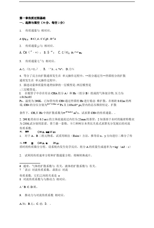
第一章传质过程基础一、选择与填空(30分,每空2分)1.传质通量与相对应。
A Q/q ;B C/_4 .C C.jft .D C A2.传质通量j,\与相对应。
A.C M("・*):B.5“:C.C/村;D. P^A■:3.传质通量七"与相对应。
A C A(U A-U M);B.C^A. c. %*; D.力%4.等分了反方向扩散通常发生在单元操作过程中:-•组分通过另-•停滞组分的扩散通常发生在单元操作过程中。
5.描述动量和质量传递类似律的一层模型是:两层模型是;三层模型是。
I.在根管子中存在有由CHA组分A)和Hc(组分B)组成的气体混合物,压力为1.013x10⁵Pa、温度为298K。
已知管内的CH4通过停滞的He进行稳态维扩散,在相距0.02m的两端,CH4的分压分别为= 6 7 8 08x1 °4 Pa及2.03x10* pa,管内的总压维持恒定。
扩散条件下,CH,在He中的扩散系数为= 675x10-5 m2/s。
试求算CH4的传质通量、。
2.298 K的水以0.5 m/s的主体流速流过内径为25mm的荼管,2知荼溶于水时的施密特数衣为2330,试分别用雷诺、普兰德一泰勒、卡门和柯尔本类比关系式求算充分发展后的对流传质系数。
三、推导(30分,每题15分)1.对于A、B二组元物系,试采用欧拉(Euler)方法,推导沿x、y方向进行二维分了传二、计算(40分,每20分)质时的传质微分方程。
设系统内发生化学反应,组分A的质量生成速率为〜kg/(m3・s)2.试利用传质速率方程和扩散通量方程,将稣转换成片。
6 通常,气体的扩散系数与有关,液体的扩散系数与有关。
7 '表示对流传质系数,取表示对流传质系数,它们之间的关系是o8 对流传质系数与与推动力相对应。
A."B.C.D.矶。
9.推动力与对流传质系数相对应。
A.知;B.匕;C.电;D.。
化工传递过程基础复习题(2009)1.何为“连续介质假定”,这一假定的要点和重要意义是什么?试解释联续性方程的物理意义。
传质分离过程习题答案
传质分离过程习题答案(总65页)--本页仅作为文档封面,使用时请直接删除即可----内页可以根据需求调整合适字体及大小--第二章习题1. 计算在和下苯(1)-甲苯(2)-对二甲苯(3)三元系,当x 1 = 、x 2 =、x 3 =时的K 值。
汽相为理想气体,液相为非理想溶液。
并与完全理想系的 K 值比较。
已知三个二元系的wilson 方程参数(单位: J/mol ): λ12-λ11=-; λ12-λ22= λ23-λ22=; λ23-λ33=- λ13-λ11=; λ13-λ33=-在T = K 时液相摩尔体积(m 3/kmol )为:=×10 -3 ;=×10 -3 ;=×10 -3安托尼公式为(p s :Pa ; T :K ): 苯:1n =(); 甲苯:1n=();对 -二甲苯:1n= ();解:由Wilson 方程得:Λ12=l l V V 12exp[-(λ12-λ11)/RT]=331091.1001055.177⨯⨯×exp[-/×]=Λ21= Λ13= Λ31= Λ23= Λ32= ln γ1=1-ln (Λ12X 2+Λ13X 3)-[3322311313233221122131321211X X X X X X X X X X X X +Λ+ΛΛ+Λ++ΛA +Λ+Λ+] =γ1=同理,γ2=; γ3= lnP 1S = P 1S = lnP 2S = P 2S = lnP 3S = P 3S =作为理想气体实际溶液,K 1=P P S11γ=, K 2=, K 3= 若完全为理想系,K 1=P P S1= K 2= K 3=2. 在361K 和下,甲烷和正丁烷二元系呈汽液平衡,汽相含甲烷%( mol ),与其平衡的液相含甲烷%。
用R -K 方程计算和Ki 值。
解:a 11=115.2242748.0c c p T R ⨯= • dm 6 • • mol -2a 22=225.2242748.0c c p T R ⨯= MPa•dm 6••mol -2b 1=11208664.0c c p T R ⨯= dm 3mol -1b 2=225.2242748.0c c p T R ⨯= dm 3mol -1 其中T c1=, P c1= T c2=, P c2=均为查表所得。
7. 化工原理 传质理论 题目(含答案)
传质理论基础-概念题(题目)[一]单选择题(1) x07a02103单向扩散中的漂流因数__________。
(1) >1 , (2) <1, (3) =1 , (4)不一定(2) x07a02107根据双膜理论,当被吸收组分在液体中溶解度很小时,以液相浓度表示的总传质系数_________。
(1)大于气相分传质系数;(2)近似等于液相分传质系数;(3)小于气相分传质系数;(4)近似等于气相分传质系数。
(3) x07a02110扩散通量式 J A=-D(dC A/dZ):可以用于多组分系统;只能用于双组分系统;只能用于稀溶液;只能用于理想气体;只能用于液相;可以同时用于液相或气相系统。
(4) x07b02100在双膜模型中,气液界面没有传质阻力的假定等同于下述论点____________。
(1)y*=y (2)x*=x (3)x i*=x i(4)y i=x i(5) x07b02104传质速率N A等于扩散通量J A的条件是:(1) 单向扩散,(2) 等分子相互扩散,(3) 湍流流动,(4) 稳定过程(6) x07b02105双组分气体混合物中,组分A的扩散系数是__________。
(1) 系统的物质属性;(2)组分A的物质属性;(3)只取决于系统的状态;(4)以上三者皆不是。
(7) x07b02106双组分气体(A,B)进行稳定分子扩散。
设J A、J B及N A、N B分别表示在传质方向上某截面处溶质A、B 的扩散通量与传质速率。
当整个系统为单向扩散时,有(1) |J A|>|J B|,|N A|>|N B| (2) |J A|=|J B|,|N A|=|N B|(3) |J A|=|J B|,,N A|>|N B| (4) |J A|=|J B|,|N A|>|N B|>0(8) x07b02112双组分气体(A、B)在进行定常分子扩散,J A及N A分别表示在传质方向上某截面处溶质A 的分子扩散速率与传质速率,当整个系统为单向扩散时:┃J A ┃(A 大于、B 等于、C 小于)┃J B ┃┃N A ┃(A 大于、B 等于、C 小于)┃N B ┃(9) x07b05066双组分理想气体混合物中,组分A 的扩散系数是——————(①系统的物质属性;② 组分A 的物质属性;③只取决于系统的状态);当系统总浓度增加时,此扩散系数将——————(①增加、;② 减少;③不变;④ 不定);当系统中组分B 的分子量增加时,此扩散系数将——————(①增加、;② 减少;③不变;④ 不定)。
第章分子传质
第十章1. 在一根管子中存在有由CH 4(组分A )和He (组分B )组成的气体混合物,压力为1.013×10⁵ Pa 、温度为298K 。
已知管内的CH 4通过停滞的He 进行稳态一维扩散,在相距0.02m 的两端,CH 4的分压分别为411008.6⨯=A p Pa 及421003.2⨯=A p Pa ,管内的总压维持恒定。
试求(1) CH 4相对于摩尔平均速度m u 的扩散通量A J ; (2) CH 4相对于静止坐标的通量A N 。
已知CH 4~He 系统在1.013×10⁵ Pa 和298K 时的扩散系数410675.0-⨯=AB D m 2/s 。
解:(1) )(21A A ABA p p zRT D J -∆=44540.67510(6.0810 2.0310) 5.521083142980.02--⨯=⨯⨯-⨯=⨯⨯⨯kmol/(m 2·s)(2) BMAA A BM AB A p pJ p p p p z RT D N =-∆=)(21 12211212ln ln A A A A B B B B BM p p p p p p p p p p p ---=-=445454410846.51008.610013.11003.210013.1ln1003.21008.6⨯=⨯-⨯⨯-⨯⨯-⨯=Pa545510565.910846.510013.11052.5--⨯=⨯⨯⨯⨯=A N kmol/(m 2·s)2. 将温度为298K 、压力为1atm 的He 和N 2的混合气体,装在一直径为5mm 、长度为0.1 m 的管中进行等分子反方向扩散,已知管子两端He 的压力分别为0.06atm 和0.02atm ,在上述条件下扩散系数410687.02--⨯=N He D m 2/s ,试求(1) He 的扩散通量; (2) N 2的扩散通量;(3) 在管的中点截面上的He 和N 2分压。
化工原理课后答案(中国石化出版社) 第8章 传质过程导论
本文由tiger2100贡献doc文档可能在WAP端浏览体验不佳。
建议您优先选择TXT,或下载源文件到本机查看。
第八章传质过程导论第八章传质过程导论1.含有 CCl 4 蒸汽的空气,由 101.3kPa(绝)、293K 压缩到 l013kPa(绝)后,进行冷却冷凝,测出 313K 下开始有 CCl 4 冷凝,混合气出冷凝器时的温度为 300K 求: (l)压缩前、压缩后开始冷凝前与出冷凝器时,CCl 4 蒸汽的质量分率、质量比和摩尔浓度。
(2)出冷凝器时 CCl 4 蒸汽冷凝的百分率。
四氯化碳的饱和蒸汽压数据如下: 273 283 288 T /K 293 89.8 300 123 313 210p / mmHg 33.7 注:1mmHg = 133.3 p a55.671.1解:(1)l013kPa(绝),313K 下开始有 CCl 4 冷凝,则210 × 101.3 760 y= = 0.0276 1013 0.0276 × 154 压缩前: a = = 0.131 0.0276 ×154 + (1 0.0276) × 29 0.0276 × 154 a= = 0.15 (1 0.0276) × 29 yp 0.0276 × 101.3 C= = = 1.15 × 10 3 kmol / m 3 RT 8.314 × 293 压缩后开始冷凝前: a = 0.131 , a = 0.15 yp 0.0276 × 10¹³ C= = = 1.07 × 10 2 kmol / m 3 RT 8.314 × 313 123 × 101.3 760 出冷凝器时: y ' = = 0.0162 1013 0.0162 × 154 a' = = 0.080 0.0162 × 154 + (1 0.0162) × 29 0.0162 × 154 a'= = 0.087 (1 0.0162) × 29第 1 页第八章传质过程导论yp 0.0162 × 1013 = = 6.58 × 10 3 kmol / m 3 RT 8.314 × 300 a a' 0.15 0.087 × 100% = 42% (2) × 100% = a 0.15 C=2.二氧化硫与水在 30℃下的平衡关系为: a (kgSO2 / 100kgH 2 O) 0.1 0.2 0.3 0.5 0.7 52 1.0 79 1.5 1254.7 11.8 19.5 36 试求总压为 101.3kPa(绝)下的 x y 关系,并作图。
- 1、下载文档前请自行甄别文档内容的完整性,平台不提供额外的编辑、内容补充、找答案等附加服务。
- 2、"仅部分预览"的文档,不可在线预览部分如存在完整性等问题,可反馈申请退款(可完整预览的文档不适用该条件!)。
- 3、如文档侵犯您的权益,请联系客服反馈,我们会尽快为您处理(人工客服工作时间:9:00-18:30)。
第一章传质过程基础
1. 质量比与质量分数、摩尔比与摩尔分数有何不同,它们之间的关系如何?
2. 某组分的绝对速度、扩散速度和平均速度各表示什么意义?
3. 传质的速度与通量为何有不同的表达方式,各种表达方式有何联系?
4. 分子传质(扩散)与分子传热(导热)有何异同?
5. 在进行分子传质时,主体流动是如何形成的,主体流动对分子传质通量有何影响?
6. 气体中扩散系数、液体中扩散系数各与哪些因素有关?
7. 对流传质与对流传热有何异同?
8. 提出对流传质模型的意义是什么?
9. 停滞膜模型,溶质渗透模型和表面更新模型的要点是什么,各模型求得的传质系数与扩散系数有何关系,其模型参数是什么?
10. 三传类比具有哪些理论意义和实际意义?
11. 对流传质系数有哪几种求解方法,其适用情况如何?
第二章气体吸收
1. 温度和压力对吸收过程的平衡关系有何影响?
2. 亨利定律为何具有不同的表达形式?
3. 摩尔比与摩尔分数有何不同,它们之间的关系如何?
4. 分子传质(扩散)与分子传热(导热)有何异同?
5. 在进行分子传质时,总体流动是如何形成的,总体流动对分子传质通量有何影响?
6. 讨论传质的机理、吸收过程的机理的意义是什么?
7. 双膜模型,溶质渗透模型和表面更新模型的要点是什么,各模型求得的传质系数与扩散系数有何关系,其模型参数是什么?
8. 吸收速率方程为何具有不同的表达形式?
9. 传质单元高度和传质单元数有何物理意义?
第三章蒸馏
1. 压力对蒸馏过程的汽液平衡关系有何影响,如何确定精馏塔的操作压力?
2. 挥发度与相对挥发度有何不同,相对挥发度在精馏计算中有何重要意义?
3. 为什么说理论板是一种假定,理论板的引入在精馏计算中有何重要意义?
4. 在分离任务一定时,进料热状况对所需的理论板层数有何影响?
5. 进料量对理论板层数有无影响,为什么?
6. 全回流操作的特点是什么,有何实际意义?
7. 对不正常形状的汽液平衡曲线,是否必须通过曲线的切点来确定,为什么?
8. 精馏操作回流比通常为,试分析根据哪些因素确定倍数的大小?
9. 若精馏塔塔顶采用分凝器-全凝器冷却方式,在求解理论板层数时应注意什么?
10.在精馏过程中,影响塔板效率的因素是什么?
第四章气-液传质设备
1.评价塔板性能的指标有哪些方面,开发新的塔板应考虑哪些问题?
2.塔板上有哪些异常操作现象,它们是如何形成的,如何避免这些异常操作现象的发生?
3.塔板负荷性能图的意义是什么?
4.塔板有哪些主要类型,各有什么特点,如何选择塔板类型?
5.综合比较板式塔与填料塔的特点,说明板式塔和填料塔各适用于何种场合?
6.评价填料性能的指标有哪些方面,开发新型填料应注意哪些问题?
7.填料有哪些主要类型,各有什么特点,如何选择填料?
8.填料塔的流体力学性能包括哪些方面,对填料塔的传质过程有何影响?
第五章液-液萃取
1.如何选择萃取操作的温度?
2.压力对萃取分离效果有何影响?
3.如何确定单级萃取操作中可能获得的最大萃取液组成?对于 >1和 <1两种情况确定方法是否相同?
4.如何选择萃取剂用量或溶剂比?
5.对于组分B、S部分互溶的物系如何确定最小溶剂用量?
6.超临界流体萃取有何特点?
7.根据哪些因素来决定是采用错流还是逆流操作流程?
第六章固体物料的干燥
1. 当湿空气的总压变化时,湿空气H–I图上的各线将如何变化? 在t、H相同的条件下,提高压力对干燥操作是否有利? 为什么?
2. 测定湿球温度tw和绝热饱和温度tas时,若水的初温不同,对测定的结果是否有影响?为什么?
3. 如何区别结合水分和非结合水分?
4. 当空气的t、H一定时,某物料的平衡湿含量为X*,若空气的H下降,试问该物料的X*有何变化?
5. 采用一定湿度的热空气干燥湿物料,被除去的水分是结合水还是非结合水?为什么?
第七章其它传质与分离过程
本章无思考题。