开利空调产品手册
开利空调轻商产品手册N-LCML-1111-02

380V-3Ph-50Hz 1.1 1.2 56 67 240 217 5 1.3 1.4 67 78 205 175 8 1.6 1.7 68 74 213 203 8 2.8 3.0 57 65 209 205 12
3.6 3.8 53 64 211 197 12
4.8 4.9 55 57 223 219 35
DN32 DN32 DN32 DN32 DN50 DN50 DN50 DN65 DN65 DN65 DN32 DN32 DN32 DN32 DN50 DN50 DN50 DN65 DN65 DN65 1580 1580 1800 1800 1330 1330 1330 1330 1330 1330 1580 1580 1800 1800 1330 1330 1330 1330 1330 1330 1100 1100 500 500 990 755 990 755 2050 2050 2050 2050 2050 2050 1100 1100 1061 1061 1061 2258 2258 2258 500 500 990 755 990 755 2050 2050 2050 2050 2050 2050 1061 1061 1061 2258 2258 2258
47
电 源 水流量
V-ph-Hz 220-1-50 220-1-50 220-1-50 380-3-50 380-3-50 220-1-50 380-3-50 220-1-50 220-1-50 220-1-50 380-3-50 380-3-50 220-1-50 380-3-50 l/s 高 (mm) 0.33 590 800 300 72 35 / 1 1" 1" 0.39 803 800 300 84 73 / 2 1" 1" 0.47 1264 800 300 107 59 / 2 1" 1" 0.47 1264 800 300 107 59 / 2 1" 1" 0.55 1264 800 300 117 52 / 2 1" 1" 5 1" 1" 0.65 1288 1043 478 165 170 0.71 1288 1043 410 155 160 / 5 1" 1" 0.31 803 800 300 84 / / 2 1" 1" 0.37 803 800 300 87 77 56 2 1" 1" 0.46 1264 800 300 111 60 51 2 1" 1" 0.46 1264 800 300 111 60 51 2 1" 1" 0.55 1264 800 300 122 54 45 2 1" 1" 0.65 1288 1043 478 179 170 145 5 1" 1" 0.68 1288 1043 410 165 166 147 5 1" 1"
开利SL1600F-TH2恒温恒湿控制器操作说明书

柜式恒温恒湿空调机组水冷型使用说明书为了使机组能够保持良好的工作状态,在安装使用之前,请详细阅读该使用说明书。
并放在便于查找的地方。
目录1.恒温恒湿控制器简述1.1.安全要求 (1)1.2.配件清单 (1)1.3.控制板的资源 (1)1.4.主要性能指标及技术特点 (1)1.5.产品简介 (2)2.操作说明 (2)2.1.按键说明 (2)2.2.操作流程图 (3)2.3.开关机 (3)2.4.主菜单页面 (3)2.5.参数设定 (4)2.5.1.用户参数设置 (4)2.6.手动调机功能 (4)2.7.输出输入状态查看 (5)3.控制逻辑 (5)3.1.拔码开关设置 (5)3.2.系统控制 (5)3.3.加湿器控制 (6)3.3.1.工作原理 (6)3.3.2.自检功能 (7)3.3.3.手动排水 (7)3.3.4.加湿开关条件 (7)3.4.冷却水泵控制 (7)3.5.压缩机延时保护 (7)4.故障检测 (8)4.1.故障处理 (8)4.2.故障查看 (9)4.3.故障复位 (9)5.接线图 (9)1.恒温恒湿机控制器简述1.1.安全要求➢请务必详尽阅读“安全要求”,并严格遵守各项安全要求。
➢妥善保管好该使用说明书,以便相关人员随时取阅。
➢指定电源为控制器供电,切勿与其它电器共用同一电源,以免导致负荷过大的危险。
➢务必保证控制器可靠接地并经常检查接地是否牢固,接地不当可能导致触电的意外。
➢安装时请遵守强弱电分离的原则。
➢按照“安装尺寸图”、“电气连接示意图”等图安装连线。
➢把控制器安装在不会有雨雪、废弃物等聚集、阳光暴晒的地方。
➢稳固安装控制器,以防控制器跌落伤人或损坏。
➢开关电源输入,85~264AC。
➢输出继电器AC220V/5A。
➢切勿拉扯、扭曲电源线、通讯线以免产生严重故障。
➢用户如有任何修理的需要,请与制造商联系,切勿自行修理。
1.2.配件清单1.3.控制板的资源1.4.主要性能指标及技术特点1.电源电压:三相380VAC/50Hz,单相220VAC/50Hz;2.控制器空载消耗功率:≤10W;3.使用环境:工作环境温度范围-10~70℃,5%RH≤相对湿度≤95%RH(无凝露);4.保存环境:温度范围-25~85℃,相对湿度≤95%RH(无凝露)。
04_30XW电气手册 开利
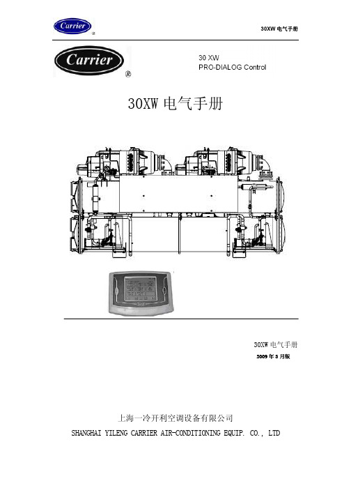
30XW 电气手册
30XW 电气手册
2009 年 3 月版
上海一冷开利空调设备有限公司 SHANGHAI YILENG CARRIER AIR-CONDITIONING EQUIP. CO., LTD
30XW 电气手册
目录
1.安全事项 ...................................................................................................................1 1.1 概述 .................................................................................................................1 1.2 避免触电 .........................................................................................................1
2.一般描述 ....................................................................................................................2 2.1 概述 .................................................................................................................2 2.2 缩写说明 .........................................................................................................3
开利空调30XAXQ电气手册_
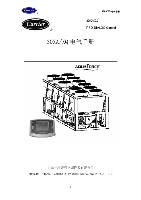
30XA/XQ电气手册上海一冷开利空调设备有限公司 SHANGHAI YILENG CARRIER AIR-CONDITIONING EQUIP. CO., LTD目 录1 安全事项 4 1.1概述 41.2避免触电 42 一般描述 5 2.1概述 52.2缩写使用 63 硬件描述 7 3.1概述 7 3.2电路板供电 8 3.3电路板上的发光二极管 8 3.4传感器 8 3.5控制 10 3.6用户接线端子联接 10 3.6.1概述 10 3.6.2设定点选择的无源触点 11 3.6.3能量限制的无源触点 113.6.4无能量限制的无源触点 114 PRO-DIALOG的设定 13 4.1用户界面板特点 13 4.2运行配置概述 1416 4.3数据显示屏4.3.1特征4.3.2自定义4.4主菜单描述 17 4.4.1表格子菜单描述 18 4.4.2时间表20 4.4.3报警4.4.4复位4.4.5运行时间4.4.6附属4.4.7设置4.4.8登录/注销 22 4.5表格描述 22 4.5.1参数点的读数 22 4.5.2参数点的修改 23 4.6时间表24 4.6.1描述4.6.2修改4.7显示器的重新初始化25 4.8显示与控制的转化4.9机组启动/停止控制4.9.1描述4.9.2启动与操作类型选择4.9.3在本地模式下停机 265.PRO-DIALOG操作方法 27 5.1启/停控制 27 5.2停机功能 28 5.3 制冷制热选择 28 5.4冷水泵控制 28 5.5流量开关 29 5.6控制点 29 5.6.1当前设定点 29 5.6.2修正功能 31 5.7能量限制 315.8电流限制 5.9夜间模式 5.10制冷量控制 5.11背压控制 29 36 36 365.12 除霜控制 36 5.13确定领先回路 37 5.14循环加载顺序 37 5.15主/从机组连接 37 5.16热回收模式选择 38 5.17冷水泵控制 39 5.18能量控制选项 39 5.19蒸发器加热器选项 40 5.20黑箱选择 40 6故障诊断 416.1概述 41 6.2报警显示 41 6.3报警复位 41 6.4报警代码描述 42 7回路能量加载顺序 497.1双回路——平衡能量加载 49 7.2双回路——给定一个回路优先权 50 7.3三回路——平衡能量加载 51 7.4三回路——给定一个回路优先权 53厂家保留设计更改并不预先通知客户的权利!1.安全事项1.1概述若忽视一些安装中的特殊因素诸如:运行压力、电气元件、电压及机组自身的安装位置,那么机组设备的安装、启动和维修将会变得十分危险。
青岛开利机组说明书
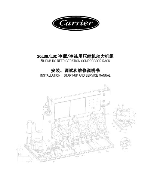
30LDM/LDC冷藏/冷冻用压缩机动力机组30LDM/LDC REFRIGERATION COMPRESSOR RACK安装、调试和维修说明书INSTALLATION,START-UP AND SERVICE MANUAL上海合众-开利空调设备有限公司SHANGHAI HEZHONG-CARRIER AIR-CONDITIONING EQUIPMENT CO., LTD. 内容1.介绍2.使用说明3.机组各主要部件名称以及外形尺寸4.机组的安装5.管路的连接6.开机程序6.1 泄漏测试6.2 抽真空充注制冷剂及开机之前的准备工作充注制冷剂并开机开机后的运行检查控制参数设定7.制冷原理7.1 30LDC制冷原理图7.2 30LDM制冷原理图8.电气原理图附件A. ELLIWELL压缩机控制器介绍A.1 通用描述A.2 人机界面A.3 输入输出A.4 进入编程模式A.5 显示/修改参数A.6 密码保护A.7 配置参数说明A.8 用户界面A.9 用户信息A.10 报警信息A.11 编码列表1.介绍30LDM/LDC冷藏/冷冻用压缩机动力机组适用于超市食品保鲜、冷库以及其它工业低温要求。
机组采用立式并联设计,结构紧凑。
使用Eliwell压缩机控制器,智能化控制系统简单可靠,可以灵活的设定机组正常运行工况点和经济运行工况点,达到节能的目的。
使用06CC单机双级压缩机,有效降低压缩比,提高机组效率和可靠性(30LDC特有)。
2. 使用范围4.机组的安装1)机组为非防雨型,应置于雨、水淋不到处;2)为防止机组结露、结霜后滴水,请对地面进行防水处理,或安装接水盘,同时,为保持并提高性能,请在吸气管上安装绝热材料;3)应做好机房通风系统,使其温度低于40℃;4)基础应采用重量为机组3倍的混凝土基础,机组的倾斜应在1°以内;5)机组采用整体减振设计,压缩机和机组管路均不设置单独的减振装置。
现场安装时,请在基础与机组间安装减振垫。
开利空调30HXC开机操作手册

(2)
->
(2)
56 阀组件
(2)
06DA403844C
(2)
->
(2)
57 压力传感器 (2)
OP12DA039
(2)
->
(2)
58 卡式接头
(2)
DC09SA110
(2)
->
(2)
59 三通
(2)
B4STWWH
(2)
->
(2)
冷凝器
60 端盖甲
(1)
09HX505572
(1)
->
(1)
61 端盖乙
(2)
XL12AL003
(2)
->
(2)
77 干燥过滤器壳体 (2)
XW12GB008
(2)
->
(2)
78 干燥过滤器芯子 (4)
XW12EA003
(4)
->
(4)
供液管组
79 三通
(2)
DE40BA723C
(2)
->
(2)
80 湿度指示仪
(2)
XS12AD003
(2)
->
(2)
81 角阀
(2)
XL12AU047
螺杆冷水机组零件清单
SERVICE PARTS GUIDE INDEX 30HXC
冷量范围(130 – 400 冷吨)
上海一冷开利空调设备有限公司
信息公布日期 29/03/2004
30HXC螺杆冷水机组零件清单
序号 零件名称
30HXC130
机组型号 30HXC165
压缩机
1 压缩机A1
30HXRIN150
XL12AU049 XL12AL005 XW12GB010 XW12EA003
开利30RARH017-033开机手册
技 术 参 数 及 电 气 参 数 ....................................................................................................4 外 形 尺 寸 /安 装 间 隙 ......................................................................................................6 安 装 ................................................................................................................................8 水 系 统 连 接 ....................................................................................................................9 电 气 连 接 ......................................................................................................................12 液 体 制 冷 剂 的 充 注 ......................................................................................................12 电 器 控 制 ......................................................................................................................13 启 动 ..............................................................................................................................14 压 缩 机 更 换 ..................................................................................................................14 水 泵 更 换 ......................................................................................................................15 保 护 装 置 ......................................................................................................................16 运 行 界 限 ......................................................................................................................16 一 般 维 护 ......................................................................................................................18 最 终 说 明 ......................................................................................................................19 故 障 排 除 表 ..................................................................................................................19
开利空调BRC4C82遥控器说明书
OPERATION MANUAL Wireless Remote Controller KitMODELBRC4C82Read these instructions carefully before installation.Keep this manual in a handy place for future reference.This manual should be left with the equipment owner.Fig. 1-1Fig. 2Fig. 1-3COOL/HEA T CHANGEOVERREMOTE CONTROL SWITCHCONTENTSILLUSTRA TIONS (3)1.SAFETY CONSIDERA TIONS (4)S AND FUNCTIONS OF THE OPERA TINGSECTION (4)3.HANDLING FOR WIRELESS REMOTECONTROLLER (5)4.OPERA TION PROCEDURE (6)5.NOT MALFUNCTION OF THE AIR CONDITIONER (9)6.HOW TO DIAGNOSE TROUBLE SPOTS (9)Please read these “SAFETY CONSIDERA TIONS” carefully before installing air conditioning equipment and be sure to install it correctly. After completing the installation, make sure that the unit operates properly during the start-up operation. Please instruct the customer on how to operate the unit and keep it maintained.Also, inform customers that they should store this operation manual along with the installation manual for future reference. This air conditioner comes under the term “appliances not accessible to the general public”.Meaning of warning, caution and note symbols.WARNING.........Indication a potentially hazardous situa-tion which, if not avoided, could result indeath or serious injury.CAUTION..........Indication a potentially hazardous situa-tion which, if not avoided, may result inminor or moderate injury. It may also besued to alert against unsafe practices.NOTE..................Indication situation that may result in equip-ment or property-damage-only accidents. Keep these warning sheets handy so that you can refer to them if needed.Also, if this equipment is transferred to a new user, make sure to hand over this operation manual to the new user.WARNING•It is not good for your health to expose your body to the air flow for a long time.•In order to avoid electric shock, fire or injury, or if you detect any abnormality such as smell of fire, turn off power and call your dealer for instructions.•Ask your dealer for installation of the air conditioner.Incomplete installation performed by yourself may result in a water leakage, electric shock, and fire.•Ask your dealer for improvement, repair, and maintenance.Incomplete improvement, repair, and maintenance mayresult in a water leakage, electric shock, and fire.•Do not put a finger, a rod or other objects into the air inlet or outlet. As the fan is rotating at high speed, it willcause injury.•Ask your dealer to move and reinstall the air conditioner.Incomplete installation may result in a water leakage, electric shock, and fire.•Do not touch the switch with wet fingers.Touching a switch with wet fingers can cause electric shock.•Do not operate the air conditioner with a wet hand. Otherwise, you could receive an electric shock.CAUTION•Do not use the air conditioner for other purposes.In order to avoid any quality deterioration, do not use the unit for cooling precision instruments, food, plants, animals or works of art.•To avoid oxygen deficiency, ventilate the room suffi-ciently if equipment with burner is used together with the air conditioner.•Do not allow a child to mount on the unit or avoid placing any object on it.Falling or tumbling may result in injury.•Do not let children play on and around the unit.If they touch the unit carelessly, it may result in injury.•Do not place a flower vase and anything containing water. Water may enter the unit, causing an electric shock or fire.•Do not operate the air conditioner when using a room fumigation - type insecticide.Failure to observe could cause the chemicals to become deposited in the unit, which could endanger the health of those who are hypersensitive to chemicals.•Never use flammable spray such as hair spray, lacquer or paint near the unit.It may cause a fire.1.2.•Precautions in handling remote controller•Direct the transmitting part of the remote controller to the receiving part of the air conditioner.If something blocks the transmitting and receiving path of the indoor unit and the remote controller as curtains, it will not operate.•Transmitting distance is approximately 23 ft..•Do not drop or get it wet.It may be damaged.•Never press the button of the remote controller with a hard, pointed object.The remote controller may be damaged.•Installation siteIt is possible that signals will not be received in rooms that have electronic fluorescent lighting. Please consult with the salesman before buying new fluorescent lights.If the remote controller operated some other electrical appa-ratus, move that machine away or consult your dealer.Placing the remote controller in the remote controller holderInstall the remote controller holder to a wall or a pillar with the attached screw. (Make sure it transmits.)NOTE•For the sake of explanation, all indications are shown on the display in Fig. 1-1 contrary to actual running situations.•Fig. 1-2 shows the remote controller with the front cover opened.•Fig. 2 shows this remote controller can be used in conjunc-tion with the one provided with the VRV system.•If the air filter cleaning time indicator lamp lights up, clean the air filter as explained in the operation manual provided with the indoor unit.After cleaning and reinstalling the air filter, press the filter sign reset button on the remote controller. The air filter cleaning time indicator lamp on the receiver will go out.•The DEFROST lamp will flash when the power is turned on. This is not a malfunction.3.HANDLING FOR WIRELESS REMOTE CONTROLLERthem whenever the indoor unit doesn’t respond or respondsslowly to commands, or if the display becomes dark.CAUTION•Replace all batteries at the same time, do not use new andold batteries intermixed.•In case the remote controller is not used for a long time takeout all batteries in order to prevent liquid leak of the battery.IN THE CASE OF CENTRALIZED CONTROL SYSTEMIf the indoor unit is under centralized control, it is necessary toswitch the remote controller’s setting.In this case, contact your dealer.•Contact your dealer to confirm your system type.•To protect the unit, turn on the main power switch 6 hoursbefore operation.•If the main power supply is turned off during operation, oper-ation will restart automatically after the power turns back onagain.Operate in the following order.•AUTOMA TIC OPERA TION can be selected only by Heatpump system or Heat recovery system.〈〈FOR SYSTEMS WITHOUT COOL/HEATCHANGEOVER REMOTE CONTROL SWITCH(Fig. 1-1~2 on page 3)〉〉Press OPERATION MODE SELECTOR button severaltimes and select the OPERATION MODE of yourchoice as follows.COOLING OPERATION................................................“”HEA TING OPERA TION.................................................“”AUTOMA TIC OPERA TION............................................“”•In this operation mode, COOL/HEA T changeover is auto-matically conducted.•FAN OPERA TION..........................................................“”DRY OPERA TION.........................................................“”•your room with the minimum temperature decrease.•The microchip automatically determines TEMPERA TUREand FAN SPEED.•This system does not go into operation if the room temper-ature is below 60°F.Press ON/OFF button.OPERA TING INDICA TOR lamp lights up or goes off and thesystem starts or stops OPERA TION.NOTE•Do not turn off power immediately after the unit stops. Then,wait no less than 5 minutes.Water is leaking or there is something else wrong with the unit.〈〈FOR SYSTEMS WITH COOL/HEAT CHANGEOVERREMOTE CONTROL SWITCH (Fig. 2 on page 3)〉〉(1)Select OPERATION MODE with the COOL/HEATCHANGEOVER REMOTE CONTROL SWITCH as follows.COOLING OPERAHEA TING OPERAFAN OPERADRY OPERA TION.....................................................•See “FOR SYSTEM WITHOUT COOL/HEATCHANGEOVER REMOTE CONTROL SWITCH” for detailson dry operation.4.OPERATION PROCEDURECOOLING, HEATING, AUTOMATIC, FAN, AND PRO-GRAM DRY OPERATION(2)Press OPERATION MODE SELECTOR button several times and select “”.Press ON/OFF button.OPERA TING INDICA TOR lamp lights up or goes off and the system starts or stops OPERATION.NOTE•Do not turn off power immediately after the unit stops. Then, wait no less than 5 minutes.Water is leaking or there is something else wrong with the unit.[EXPLANATION OF HEATING OPERATION]DEFROST OPERATION•As the frost on the coil of an outdoor unit increase, heating effect decreases and the system goes into DEFROST OPERA TION.•The fan operation stops and the DEFROST lamp of the indoor unit goes on.•After 6 to 8 minutes (maximum 10 minutes) of DEFROST OPERA TION, the system returns to HEA TING OPERA TION.Heating capacity & Outdoor air temperature•Heating capacity drops as outdoor air temperature lowers.If feeling cold, use another heater at the same time as this air conditioner.•Hot air is circulated to warm the room. It will take some time from when the air conditioner is first started until the entire room becomes warm. The internal fan automatically turns atlow speed until the air conditioner reaches a certain temper-ature on the inside. In this situation, all you can do is wait.•If hot air accumulates on the ceiling and feet are left feeling cold, it is recommended to use a circulator. For details, con-tact the place of purchase.For programming TEMPERA TURE and FAN SPEED, follow the procedure shown below.Press TEMPERATURE SETTING button and program the setting temperature.Each time this button is pressed, setting tempera-ture rises 1°F .Each time this button is pressed, setting tempera-ture lowers 1°F .In case of automatic operationEach time this button is pressed, setting tempera-ture shifts to “H” side.Each time this button is pressed, setting tempera-ture shifts to “L ” side.[°F]•The setting is impossible for fan operation.NOTE•The setting temperature range of the remote controller is 60°F to 90°F .Press FAN SPEED CONTROL button.High or Low fan speed can be selected.The microchip may sometimes control the fan speed in order to protect the unit.Operate in the following order.•The timer is operated in the following 2 ways.•The timer can be programmed a maximum of 72 hours.•The start and the stop time can be simultaneously programmed.Press the TIMER MODE START/STOP button several times and select the mode on the display.The display flashes.Press the PROGRAMMING TIMER button and set the time for stopping or starting the system.When this button is pressed, the time advances by 1 hour.When this button is pressed, the time goes back-ward by 1 hour.Press the TIMER RESERVE button.The timer setting procedure ends.The display changes from flashing light to a constant light.Press the TIMER CANCEL button to cancel programming.The display vanishes.ADJUSTMENTH•M •L Setting temperature7773717066PROGRAM TIMER OPERATIONFor example.When the timer is programmed tostop the system after 3 hours andstart the system after 4 hours, thesystem will stop after 3 hours andthen 1 hour later the system will start.NOTE•After the timer is programmed, the display shows the remain-ing time.•When the system is installed as shown below, it is necessary to designate the master remote controller.For Heat pump systemWhen 1 outdoor unit is connected with several indoor units.For Heat recovery systemWhen 1 BS unit is connected with several indoor units.•Only the master remote controller can select HEA TING,COOLING or AUTOMA TIC OPERA TION.When the indoor unit with master remote controller is set to “COOL”, you can switch over operation mode between “FAN”, “DRY” and “COOL”.When the indoor unit with master remote controller is set to “HEA T”, you can switch over operation mode between “FAN” and “HEA T”.When the indoor unit with master remote controller is set to “FAN”, you cannot switch operation mode.1 long beep..............When attempting settings than that con-sented above.Only with Heat recovery system, you canset the indoor unit to AUTOMA TIC.Attempting to do so.How to designate the master remote controller Operate in the following order.Continuously press the OPERATION MODE SELEC-TOR button for 4 seconds.Press the OPERATION MODE SELECTOR button tothe indoor unit that you wish to designate as the mas-ter remote controller. Then designation is completed.This indoor unit is designated as the master remotecontroller and the display showing “•To change settings, repeat steps and .When the remote controller does notwork due to battery failure or theabsence there of, use this switch whichis located beside the discharge grille onthe indoor unit. When the remote con-troller does not work, but the battery lowindicator on it is not lit, contact yourdealer.[START]Press the EMERGENCY OPERATIONswitch.The machine runs in the previous mode.[STOP]Press the EMERGENCY OPERATIONswitch again.This system provides 2 other control systems beside individualcontrol (1 remote controller controls 1 indoor unit) system. Confirmthe following if your unit is of the following control system type. HOW TO SET MASTER REMOTE CONTROLLER(For VRV system)EMERGENCY OPERATIONPRECAUTIONS FOR GROUP CONTROL SYSTEMOR 2 REMOTE CONTROLLERS CONTROL SYSTEM1212Group control system1 remote controller controls up to 16 indoor units.All indoor units are equally set.2 remote controllers control system2 remote controllers control 1 indoor unit.(In case of group control system, 1 group of indoor units) The unit follows individual operation.NOTE•Cannot have 2 remote controllers control system with only wire-less remote controllers. (It will be a 2 remote controllers control system having 1 wired and 1 wireless remote controllers.)•Under 2 remote controllers control system, wireless remote controller cannot control timer operation.•Only the operating indicator lamp out of 3 other lamps on the indoor unit display functions.•Contact your dealer in case of changing the combination or set-ting of group control and 2 remote controllers control systems. The following symptoms do not indicate air condi-tioner malfunction.THE SYSTEM DOES NOT OPERATE•The system does not restart immediately after the ON/ OFF button is pressed.If the OPERA TING INDICA TOR lamp lights, the system is in normal condition. It does not restart immediately because a safety device operates to prevent overload of the system.After 3 minutes, the system will turn on again automatically.•The system does not restart immediately when TEM-PERATURE SETTING button is returned to the former position after pushing the button.It does not restart immediately because a safety device oper-ates to prevent overload of the system. After 3 minutes, the system will turn on again automatically.•If the reception beep is rapidly repeated 3 times.(It sounds only 2 times when operating normally.)Control is set to the optional controller for centralized control.•If the DEFROST lamp on the indoor unit’s display is lit when heating is started.This indication is to warn against cold air being blown from the unit. There is nothing wrong with the equipment.The unit stops operation from time to time.•With “U4” “U5” displayed on the remote controller, the unit stops, but it resumes operation in a few minutes.Since electric noises produced from other equipment than the air conditioner interrupt communication between theunits, the unit stops operation.If these electric noises subside, operation is restarted auto-matically.COOLING / HEATING changeover is impossible.•If the indoor unit emits a receiving sound “1 long beep”.It is because the indoor unit under the control of operation changeover is set to the mode that cannot be selected. Display Indicates only a part.•Even if the unit is in operation, the display shows only operational indication. Even if the indication is shown, the indication other than operation disappears after a while.It is because the remote controller is set to multi-system.Display disappears or shows all indication.•It happens when the button of the remote controller is pressed.It is because the battery is dead.No favorable cooling is achieved.•The unit is in DRY OPERATION.DRY OPERA TION is carried out to perform operation such that the room temperature is not decreased as much as possible. EMERGENCY STOPWhen the air conditioner stops in emergency, the run lamp on the indoor unit starts blinking. T ake the following steps yourself to read the malfunction code that appears on the display. Con-tact your dealer with this code. It will help pinpoint the cause of the trouble, speeding up the repair.Press the INSPECTION/TEST OPERATION button toselect the inspection mode “ ”.Press PROGRAMMING TIMER button and change the unit number.Press to change the unit number until the indoor unit beeps and perform the following operation according to the number of beeps. Number of beeps3 short beeps...........Perform all steps from to .1 short beep.............Perform and steps.1 long beep..............Normal state5.6.3636Press OPERATION MODE SELECTOR button.“” on the left-hand of the malfunction code blinks.Press PROGRAMMING TIMER button and change the malfunction code.Press until the indoor unit 2 beeps.Press OPERATION MODE SELECTOR button.“” on the right-hand of the malfunction code blinks.Press PROGRAMMING TIMER button and change the malfunction code.Press until the indoor unit makes 1 long beep.The malfunction code is fixed when the indoor unit makes 1 long beep.Reset of the displayPress OPERATION MODE SELECTOR button to get the display back to the normal state.IN CASE BESIDES EMERGENCY STOP •The unit does not operate at all.•Check if the receiver is exposed of sunlight or strong light. Keep receiver away from light.•Check if there are batteries in the remote controller. Place the batteries.•Check if the indoor unit number and wireless remote con-troller number are equal.Operate the indoor unit with the remote controller of the same number.Signal transmitted from 1 remote controller of a different number cannot be accepted. (If the number is not mentioned, it is con-sidered as “1”.)The system operates but it does not sufficiently cool or heat.•If the set temperature is not proper. (See page 7)•If the FAN SPEED is set to LOW SPEED. (See page 7)Contact the place of purchase in the following case.WARNINGWhen you detect a burning odor, shut OFF power immedi-ately and contact the place of purchase. Using the equipment in anything but proper working condition can result in equip-ment damage, electric shock or fire.[Trouble]The OPERATING INDICATOR lamp of the indoor unit is flashing and the unit does not work at all.Check the malfunction code (A1 - UF) on the remote controller and contact the place of purchase. (Refer to indoor unit installa-tion manual.)3P153711-1EM04A060(0505)FS。
开利模块机控制器说明书
开利模块机控制器说明书开利模块机控制器是一种用于控制家用空调和供暖设备的设备。
它通过接收用户的输入信号,并根据预设的程序来控制空调和供暖设备的运行。
这篇文章将详细介绍开利模块机控制器的功能和使用方法。
第一部分:开利模块机控制器的功能开利模块机控制器具有多种功能,可以满足不同用户的需求。
首先,它可以实现温度控制功能。
用户可以通过控制器上的温度调节按钮来调整室内温度。
控制器会根据用户设定的温度值来自动调节空调或供暖设备的运行。
其次,开利模块机控制器还具有定时功能。
用户可以设置定时开关机时间,使空调或供暖设备在预设时间自动启动或关闭。
此外,控制器还可以根据用户的需求调整风速和模式,如自动、制冷、制热和通风等。
第二部分:开利模块机控制器的使用方法使用开利模块机控制器非常简便。
首先,用户需要将控制器与空调或供暖设备进行连接。
通常,控制器会提供一个与设备连接的接口,用户只需将接口插入设备的控制端口即可完成连接。
接下来,用户需要按照说明书上的指引进行设置。
首先,用户需要设置温度值。
通过按下温度调节按钮,用户可以逐步增加或减少温度值,直至达到所需温度。
然后,用户可以根据需要设置定时开关机时间。
通过按下定时设置按钮,用户可以进入定时设置界面,然后按照提示设置预设时间。
最后,用户可以选择风速和模式。
通过按下风速和模式设置按钮,用户可以选择不同的风速和模式。
第三部分:开利模块机控制器的优势开利模块机控制器具有多种优势。
首先,它可以提高空调和供暖设备的使用效率。
通过精确的温度控制和定时开关机功能,控制器可以避免不必要的能源浪费,从而降低能源消耗。
其次,控制器的使用也非常方便。
用户只需按下几个按钮即可完成所有设置,无需复杂的操作步骤。
此外,控制器还可以提供实时的温度显示,方便用户了解当前室内温度。
最后,开利模块机控制器还具有良好的稳定性和可靠性。
它采用先进的控制技术和高质量的元件,能够长时间稳定运行,减少故障率。
第四部分:开利模块机控制器的适用范围开利模块机控制器适用于各种家用空调和供暖设备。
开利30RA&30RH040A-240A开机运行维护手册
30RA/RH 040-240 A涡旋式风冷冷水/热泵机组制冷量:38.3~245kW制热量:39.2~229kW上海一冷开利空调设备有限公司SHANGHAI YILENG CARRIER AIR-CONDITIONING EQUIPMENT CO.,LTD目录1 介绍...............................................................................3 1.1 安装安全要求...................................................................3 1.2 压力设备和部件.................................................................3 1.3 维护安全事项...................................................................3 1.4 维修安全措施...................................................................4 2 预检...............................................................................5 2.1 设备进场的检验.................................................................5 2.2 机组的搬运和就位...............................................................6 3 外形尺寸/安装间隙..................................................................7 4 机组技术参数.......................................................................9 5 电气数据..........................................................................11 6 运用数据..........................................................................13 6.1机组运行范围...................................................................13 6.2交换器水流量...................................................................14 6.3 最小水流量....................................................................14 6.4 热交换器中的最大流量..........................................................14 6.5 循环水量......................................................................14 6.6机组在满负荷和部分负荷下的运行范围.............................................15 6.7 板式热交换器中的压降..........................................................17 7 电气连线..........................................................................18 7.1电源...........................................................................19 7.2电压不平衡率(%)..............................................................19 8 推荐连线部分......................................................................19 8.1 30RH现场控制连线..............................................................20 8.2 30RA现场控制连线..............................................................20 9 水管连接..........................................................................20 9.1管路设计安装注意事项...........................................................21 9.2水系统的连接...................................................................21 9.3防冻保护.......................................................................21 10 流量控制.........................................................................23 10.1水流量控制流程................................................................23 10.2系统压降作用下的水泵的曲线和流量控制..........................................24 10.3水泵压力/流量曲线.............................................................25 10.4可用的系统静压................................................................26 11 启动.............................................................................27 11.1 预检.........................................................................27 11.2 开机.........................................................................27 11.3 两台机组在主/从联动模式下运行................................................27 11.4辅助电加热器..................................................................28 12 维护.............................................................................30 12.1制冷剂环路的维护..............................................................30 12.2电气维护......................................................................33 12.3冷凝盘管......................................................................34 13 AQUASNAP维护程序...............................................................34 13.1维护时间表....................................................................34 13.2维护说明......................................................................34 14 AQUASNAP遥控操作器使用说明.......................................................37 15 30RA/RH冷水/热泵机组启动调查表(供现场安装使用).................................41 本公司保留对此说明书有关内容进行修改而不预先通知用户的权利 1 介绍在启动30RA/RH机组前,所有涉及现场安装、开机、运行和维护的人员应当仔细阅读本操作说明书。