
无线电导航原理和机载设备简介(Principles of radio navigation and airborne equipment)
无线电导航原理和机载设备简介(Principles of radio navigationand airborne equipment)Principles of radio navigation and airborne equipmentEarly aircraft flying in the air relied solely on landmark navigation - the linear landmarks that looked at roads, railways, rivers, etc.; landmarks such as peaks, lighthouses, road interchanges, etc.; landmarks such as lakes and towns. Later, aviation map, compass, slipstick, clock and other tools and their astronomy, geography, mathematics knowledge by aircrew, according to the wind speed and wind direction calculation route angle, combined with landmark fix route deviation, this work is called "air navigation". This method is the "original", but Lin Bo aviation pioneer is to rely on these things when driving a single engine piston aircraft "spirit of Saint Louis" alone from the west coast of the United States set out directly over the Atlantic arrived in Paris, he flew over the vast the Atlantic is through observation of the sea currents, the night sky in the constellation to identify the direction determine the position. Air navigation is a required course for pilots. The key is to modify the influence of wind on flight path by using the principle of vector composition.With the development of radio technology, every kind of electronic equipment provide accurate navigation information for aircraft: for the Omega Navigation System (OMEGA), intercontinental navigation Loran system suitable for a wide sea level (LORAN-A, LORAN-C), for VHF omnidirectional radio short-range navigation standard navigation system (VORTAC),and some for the military development of navigational beacons and radar system. Now, the global positioning system (GPS), which uses geostationary satellites, has begun to be widely used. But VORTAC is still the mainstream of short-range navigation, and most modern military and civilian aircraft, including civil aircraft and small general-purpose aircraft, are equipped with VOR receivers (VOR, very, high, frequency, ommi-directional, range).VORTAC is a general term for VOR/DME and TACAN. VOR/DME is a civilian system, TACAN is developed for shipborne mobile stations, military tactical air navigation system (i.e. the TACAN navigation system). Both work principles and technical specifications are different, but the use of them is exactly the same. In fact, some VOR/DME and TACAN transmitting stations is built together, using the same frequency, the aircrew, just a VOR beacon. VOR beacons are the most important and important radio navigation points in the world. Many of the VOR stations separated by a distance into a network like distribution, when the signal receiver on the aircraft received the VOR beacon, pilots can determine the relative position of the aircraft and the launch station through a special instrument, if the station signal is band ranging (DME, distance measuring equitment), and also know the plane and the station distance, so as to determine the current position of the aircraft, and to know the degree of the flight angle to fly to the destination.Fundamentals of VOR/DME/NDBVOR:very, high, frequency, ommi-directional, range, VHF omnidirectional radio beaconThe operating frequency of the VOR signal transmitter and receiver is between 108.0-117.95 and MHz. The VOR signal transmitted by the transmitter stations have two: one is the phase of the reference signal of the stationary phase; another signal is changing, at the same time as the lighthouse to rotate searchlights every 360 degrees and launch phase signal to launch various angles are different, and their reference signal the phase difference is naturally different. A signal to the 360 degree (pointing to the magnetic north pole) is in phase with the reference signal, while the signal to the 180 degree (pointing to the magnetic pole) is 180 degrees from the reference signal. The VOR receiver on the aircraft can determine the angle at which the aircraft is at the station, based on the phase difference between the two signals received. That is to say, it is possible to determine which radius of the aircraft is at the center of the station transmitter.The signals sent by VOR stations form 360 "radii" that radiate in all directions, each of which is called a "Radial"".If the plane is located in the flat state: VOR station (the station codenamed POU) the South East, toward the station to station, which changed over the course, to the southwest. Navigation terms: aircraft along the POU 135 Radial (R-135), (inbound) to the station, namely the magnetic heading of 315 degrees at POU, along the R-225, fly away from the station (outbound), namely the magnetic heading of 225 degrees. Note: when the plane along a Radial fly away from the station, which is the magnetic heading Radial number; but when the plane flew along a Radial station, the magnetic heading and the Radialnumber 180.Because the radio signal VOR and television broadcast, radio FM radio, is a straight line, the mountain will be obstructions such as, so even if the distance is very near, on the ground are rarely able to receive a VOR signal, usually to fly up to 2000-3000 from the ground feet to receive signals, fly higher, receiving the distance is far away. At 18000 feet (5486 meters), the maximum receiving distance of VOR is about 40 to 130 nautical miles (1 nautical miles =1.852 kilometers), depending on factors such as visual impairment and obstruction. Above 18000ft, the maximum receiving distance is about 130 nautical miles.DME:distance, measuring, equitment, ranging deviceAs mentioned earlier, some VOR stations with DME, DME in UHF band. But the aircrew ignore its frequency, as long as a good tune the frequency of VOR, the signal is received, after a while, the distance calculated numbers will be displayed on the dashboard. Simple working principle is this: Airborne DME transmitting signals to the ground station on the DME, and receives the DME response back ground signal, measuring the transmitted signal and should sign signal time difference, half the time difference, can be calculated distance between aircraft and ground stations. However, it should be noted that the distance shown on the instrument panel is the distance from the slope of the aircraft to the ground station, and the unit is nautical mile. By the Pythagorean theorem, the plane projection and the ground station in the distance should be slightly less than the distance from the edge. Similarly, DMEdisplay on the dashboard of speed is "oblique", said the plane and station "distance shortening rate", is a unit of festival, it is not equal to the speed, is not equal to the speed. According to the DME display range and speed, can roughly estimate the aircraft ground speed and the time required to reach the station.NDB:non-directional beacon, NDB, or "radiophare"NDB is the oldest electronic navigation device still in use today, with inexpensive Chang Jianyou stations near NDB, where there is no instrument landing system, used as navigation and landing guidance. The name "non directional" means that the signals transmitted by each station in the same direction are not the same as each other in VOR. The NDB signal receiver on the aircraft is called ADF (automatic, direction, finder, azimuth indicator). The instrument head of ADF has only one pointer, and when the NDB signal is received, the pointer of ADF points to the direction in which the NDB station is located. If the plane flew straight toward the station, pointer is pointing to the front, when the plane flew over the station and continue to fly forward, the pointer will turn 180 degrees toward the rear.Introduction of airborne electronic navigation equipmentHere is the first clear look at: VOR and NDB are respectively the ground stations, transmitting VOR signal and NDB signal to the plane Nav1, Nav2 and ADF receiver in FS98, Cessna182S or Shift-2 button fly below Mouse click on the dashboard "avionics master switch control panel you can see these receivers (alsosee airborne DME, automatic control panel driving equipment).The three receivers, Nav1, Nav2 and ADF, have a circular instrument head mounted on the right side of the aircraft's main dashboard, in addition to the control panel, indicating specific navigation information.The instrument heads connected to the Nav1 and Nav2 receivers are called OBI, OBI1 and OBI2, respectively. The airborne DME also connects to a rectangular digital header,Install on top of these three round heads.COM1 and Nav1 panelsCOM1: VHF radio station, frequency range 118.0-136.975MHz.Nav1: can receive VOR signal and complete ILS signal, frequency range 108.0-117.95MHz.Nav2 panelNav2 is only used to receive VOR signals. Click the number with Mouse to change the reception frequency.ADF panelReceive NDB signal, frequency range 200-400KHzAirborne DME panelThe number on the left is the calculated distance and speed. The R1/R2 switch on the right is used to toggle the DME calculations that show Nav1 and Nav2.Responder panel (transponder)Receive air traffic control radar signals, and respond to the launch of four bit digital signals to air traffic control radar, allowing air traffic controllers to see the plane's position on the radar, or even height.Autopilot control panel (autopilot)DME headerDisplays distance, speed, and time to the selected VOR station from left to right, with Nav1, Nav2 display switches below.OBI2The Omni-Bearing Indicator, the instrument connected to the Nav2 receiver, displays the VOR information.OBS knobOmni-Bearing Selector, so that the dials rotate to select the line (Radial)CDI pointerCourse, Deviation, Indicator, line deviation indicator,indicating the current position of the aircraft on the selected route (Radial) of the OBS, leaning to the left or leaning to the right.To/From/Off signThe triangle represents the To upward; the triangle down indicates From; the red white bar indicates that Off-- has not received the selected Radial signal of the OBSOBI1Omni-Bearing Indicator, the instrument connected with the Nav1 receiver, besides the function of OBI2, it also shows the horizontal and vertical position information of the approach landing of instrument landing system (ILS).GS signThe To/From/Off flag moves below. The GS flag is added to indicate whether or not the ILS (Glide Slope) signal is received. The red and white bars indicate that the signal cannot be received. At this point, the slide indicator is not activated and does not work.Glide slope pointerIndicates the deviation between the current height of the aircraft and the required height of the ILS slipway.ADFThe Automatic, Direction, Finder, and header connected to the NDB receiver are called "azimuth indicators"".After receiving the signal, the pointer points directly to the location of the station.The knob and dial are purely mechanical auxiliary display devices, independent of pointer pointing and signal reception.The function of the knob and dial is to indicate the degree of difference between the heading to be taken from the station and the current course of the aircraft. The chart shows, stations in the left front of the aircraft, the deviation angle between 20-25 degrees.Sum up:1 and VOR are ground-based transmitting stations, and Nav is an airborne receiver.2, receiver Nav has control panel, press Shift-2 to open is the control panel, in the above can adjust the Nav receiving frequency.3, receiver Nav and instrument head, called OBI, it is installed on the main dashboard of the aircraft to the right, showing specific navigation information.4, the whole OBI (instrument head) consists of four parts: CDI pointer, To/From/Off mark, OBS knob, dial.5, the instrument head OBI1 connected by Nav1 itself can indicate the VOR information (same as OBI2).6, in order to indicate the ILS information of the instrument landing system, OBI1 has more than one GS sign and a glide path pointer over the OBI2. The GS flag indicates whether to receive the signal, the glide slope pointer, and the CDI two pointers, respectively, indicating the horizontal and vertical position information of the ILS.The next article begins with a detailed description of how to navigate and land using VOR/DME, NDB, ILS signals, and airborne electronic devices. But first we must understand the principles mentioned above and memorize the concepts and their abbreviations.Redstar (CFSO002)。
106-5元-模拟飞行-NDB使用方法及举例--澳门飞香港-文章

★NDB使用方法及举例--澳门飞香港★从澳门国际机场飞往香港启德机场,练习沿指定航向飞向NDB、用IGS 进近、目视转弯着陆。
请先参阅前文《无线电导航原理和机载设备简介》,了解NDB的信号特点、座舱中的方位角指示器(ADF表头)的组成和航电设备控制面板上的接收频率设置。
NDB的使用比VOR简单得多,接收到信号时无论飞机怎样转向,ADF指针都会指向NDB发射台所在方位,就象指南针总是指向磁北极一样。
表头上的刻度盘是用来读取角度差的,与信号接收无关,一般不必旋转这个刻度盘。
一、飞行计划(Flight Plan)二、资料准备查阅下面的启德机场13跑道进近航线图,了解有关信息:跑道(磁)航向为135度,而进近航向为88度,IGS跑道,与一般的ILS跑道的差别在于进近的末段要向右作47度(135-88=47)的目视转弯才能对准跑道中心线。
这就是启德机场“举世闻名”的直接原因。
IGS频率为111.9。
跑道接地区海拔标高为15英尺,ATIS频率为128.2,用COM收听可得知场压(这里通常是29.91),以校正高度表。
沙螺湾NDB(SHA LO WAN,SL)在88度最后进近航线(Final Approch)的南面,从下面的进近航线剖面图可见,切入进近航线的方法是:在4500英尺高度上通过沙螺湾NDB,以45度磁航向进入。
正常的进近航线是应从长洲VOR(CHEUNG CHAU,CH)、在6000英尺高度上开始的。
这次我们为了练习使用NDB,从沙螺湾开始飞进近航线。
三、飞行过程空中飞行过程包括:起飞离场,左转飞向沙螺湾NDB,同时爬升到巡航高度4500英尺,之后增速至120节,通过沙螺湾后,以45度航向切入IGS进近航线,最后目视右转弯着陆。
选机型Cessna182S,按键Shift-数字8,然后Ctrl-Enter三次,调整前视角度。
在FS98选菜单/World / go to .../ Airport.../,在airport name...栏打入macau,将飞机的位置移到澳门国际机场的RWY16上。
无线电导航的原理与应用

无线电导航的原理与应用一、导言无线电导航是一种利用无线电信号进行定位和导航的技术。
它广泛应用于航空、航海、车载导航和无人机系统等领域。
了解无线电导航的原理与应用对于理解现代导航系统的工作方式至关重要。
本文将深入介绍无线电导航的原理和其在不同领域的应用。
二、无线电导航原理无线电导航是基于无线电波传播的定位和导航技术。
其原理基于以下几个关键要素:1. 信号发射器无线电导航的系统中,会有一个或多个信号发射器,常用的是卫星导航系统中的卫星。
信号发射器会发送特定频率的无线电波信号。
2. 接收器接收器负责接收信号发射器发出的无线电波信号,并将其转化为导航系统能够识别和处理的信息。
3. 测距原理无线电导航中常用的测距原理包括时间测距、多普勒效应和信号强度测距等。
这些原理可以通过接收到的信号特征来确定位置和距离。
4. 三角定位法利用多个信号发射器和接收器,可以采用三角定位法来确定准确的位置。
通过测量不同信号到达接收器的时间差和距离,可以计算出接收器的位置。
三、无线电导航的应用1. 航空导航航空领域是无线电导航最常见的应用之一。
航空导航系统利用全球定位系统(GPS)等技术,能够实时、准确地定位飞机的位置。
无线电导航在航空领域中的应用使得飞行变得更加安全和高效。
2. 航海导航航海导航依赖于无线电导航系统来确定船只的位置和航向。
借助GPS和其他卫星导航系统,船只可以在海上定位和导航,避免撞船和迷航等危险情况。
3. 车载导航车载导航系统利用无线电导航原理来为驾驶员提供路线指引和实时导航。
通过全球定位系统和地图数据,驾驶员可以更好地规划行驶路线并避开交通拥堵。
4. 无人机导航无人机的导航是依赖于无线电导航技术实现的。
无人机可以利用GPS等定位系统精确导航,实现自主飞行和遥控飞行。
5. 军事应用无线电导航在军事领域也有广泛的应用。
军事导航系统能够为士兵和战机提供准确的定位和导航信息,提升军事行动的效率。
结论无线电导航作为一种基于无线电信号的定位和导航技术,广泛应用于航空、航海、车载导航和无人机等领域。
07无线电导航设备

莫尔斯电码
基本单位:. -= … . –间隔= .. 字母、数字间隔= ……. SOS = … --- …
2.机载设备
⑴ 天线
垂直天线 环形天线
自动接收机
接收机
音频信号 低频信号 低频信号
耳机 指示器 环形天线
控制盒 OFF:设备断电; ANT:垂直天线位置; ADF:自动定向; TEST:测试。
测距机 DME
功用
• 测距机系统是一种能够测量由询问器到某个固定应答器(地面 台)距离的二次雷达系统,工作在L频段。
• 测距机是目前民用飞机普遍装备的一种无线电导航系统,它与 VOR台常安装在一起,可用于飞机定位、测高、等待飞行、进近 着陆、航路间隔、避开保护空域及计算地速等。
• 机载测距机与地面测距信标台配合工作,用于测量飞机与地面 测距台的斜距。最大测量范围为0 390海里。
飞机不在预选航道上,过台情况。
例4:已知:CDI如图所示。 求:判断偏航情况画出飞机与VOR台的位置关系图 解:预选航道0°,偏离7°;飞机偏右。
利用CDI实现VOR导航和定位
利用CDI测定VOR径向方位
1.调好频率,听清电码; 2.调偏离杆回中; 3.CDI指示的就是VOR方位; 4.向背台指标指示背台,
无线电方位的测量
自动定向仪ADF(无方向信标机)系统 甚高频全向信标VOR系统
自动定向仪 ADF
ADF系统概述
自动定向机ADF(Automatic Direction Finder)又称 无线电罗盘,他与地面导航台NDB(Non-direction Radio beacon)配合,通过机载的环形天线测量地面导 航台发射的无线电波的来波方向测得RB。ADF系统是一 种典型的测角系统。
无线电导航设备与系统
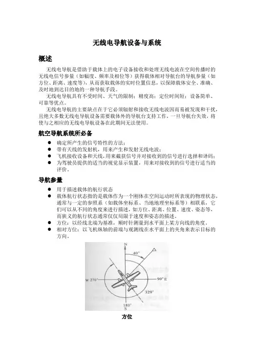
无线电导航设备与系统概述无线电导航是借助于载体上的电子设备接收和处理无线电波在空间传播时的无线电信号参量(如幅度、频率及相位等)获得载体相对导航台的导航参量(如方位、距离、速度等),从而获取载体的实时位置信息,以保障载体安全、准确、及时地到达目的地的一种导航手段。
无线电导航具有不受时间、天气的限制;精度高;定位时间短;设备简单、可靠等优点。
无线电导航的主要缺点在于它必须辐射和接收无线电波因而易被发现和干扰,且绝大多数无线电导航设备需要载体外的导航台支持工作,一旦导航台失效,将使与之相应的无线电导航设备在此期间无法使用。
航空导航系统所必备●确定所产生的信号特性的方法;●带有天线的发射机,用来产生和发射无线电波;●飞机接收设备和天线,用来截获信号并对接收到的信号进行选择和译码;●为驾驶员提供的适当的视觉显示装置,用来对接收到的信号进行适当的评价。
导航参量●用于描述载体的航行状态●载体航行状态指的是载体作为一个刚体在空间运动时所表现的物理状态,通常与一定的参照系(如载体坐标系、当地地理坐标系等)相联系,它们可以从不同的角度来进行描述,如方位、距离、位置、速度、姿态等,而狭义的航行状态通常仅仅局限于速度和姿态的描述。
●方位:以经线北端为基准,顺时针测量到水平面上某方向线的角度。
●相对方位:以飞机纵轴的前端与观测线在水平面上的夹角来表示目标的方向。
方位相对方位基本原理在二维或三维空间中,若导航台的位置已知,相对于该位置的某一导航参量相同的点的轨迹应为一条曲线或一个曲面,该曲线或曲面称为位置线或位置面;单值确定载体的位置,至少需要测定两条位置线(在二维空间内)或三个位置面(在三维空间内),根据相交定位法实现定位。
位置线(a)圆位置线;(b)直线位置线;(c) 等高线;(d)双曲线位置线相交定位 位置线定位原理☐ 如果通过无线电方式测量到了三个独立的几何参量,则可以得到,三个独立的位置面方程:⎪⎩⎪⎨⎧===),,(),,(),,(332111z y x f u z y x f u z y x f u☐ 因而可以得到载体在空间中的三维位置。
无线电导航原理与系统-

引导各种运载体飞机船舶车辆等以及个人按既定航线航行的过程称为导航它是保证运载体安全准确地沿着选定路线准时到达目的地的一种手段无线电导航系统一般由装在运载体上的导航设备和设在地面或卫星上的导航台站组成通过在导航设备和导航台站之间的无线电信号传播和通信获得导航信息给飞机或船只指示出它们的实时位置或方位使运载体在不同的运动空间和环境不同的气象气候条件下都能够顺利地完成导航任务确定运载体当前所处的位置及其航行参数包括航向速度姿态等实时运动状态
二. 无线电导航的基本知识
导航系统的分类 按所测量的电气参量 振幅式,相位式,频率式, 脉冲(时间)式,复合式 测角 ,测距 ,测距差
按所测量的几何参量 按系统的组成情况
自主式(自备式) ,非自主 式(它备式) 按无线电导航台(站)的 陆基 ,空基,星基 安装地点 按有效作用距离 近程 ,远程
按工作方式 有源 ,无源
三.无线电导航的应用及发展历史
②
GPS和GLONASS卫星导航系统:
1973 年美国国防部开始研制第二代卫星导 航 系 统 , 即 现 在 的 GPS ( Navigation Satellite Timing And Ranging/Global Positioning System, NAVSTAR GPS),其全称为“导航星授时和测距 全球定位系统”。 GPS 于 1994 年部署完毕,全部 24 颗卫星升 空, 1996 年进入“完全工作能力( FOC)阶段”。
【无线电导航原理】第2章_自动定向机

sin
b
cos
cos
ωct
E
h O,,
O,
O
x ✓ 天线在水平面具有方向
A
F D Sk
性✓ ;e0(t)与 (t)存在90 相
y
位差。
中国民航大学 CAUC
2.2 环形天线特性分析
二、天线的方向性图(1)
(t)
2Emoh
sin
b
cos
cos
ωct
令F (
)
2
Emoh
s
in
b
cos
垂直面
中国民航大学 CAUC
2.4 无方向信标
二、莫尔斯(Morse)识别码(1) ➢ 每个NDB台都必须辐射台站识别码,否则其 辐射的场无效; ➢ 一个NDB台的台站识别码一般是本地地名的 2~3个英文字母缩写的Morse电报码; ➢ ICAO规定:
✓ “点”的持续时间为0.1~0.160 s ,“划”的 持续时间为“点”的3倍,即0.3~0.480s ;
;✓ 终端NDB必须工作在“调幅报
”状态。
e(t)=Emcos ct
NDB
中国民航大学 CAUC
2.5 自动定向机工作原理
一、ADF的一般特性(1)
➢ 工作频段与波道
f =190.00~535.00kHz,
道。 ➢
波的传播与极化方式
✓ 地波传播;
✓ 垂直极化。
➢ 工作体制
f =1kHz,共345个频
2.1 概 述
四、ADF-NDB在导航中的应用(1)
1. 定位
N
A
NDB-A
LB
LA
N
M
B
NDB-B
导航工程技术专业学习教程无线电导航原理与技术
导航工程技术专业学习教程无线电导航原理与技术导航工程技术专业学习教程:无线电导航原理与技术无线电导航是现代导航系统中的重要组成部分,它利用无线电信号来确定目标位置和导航航行的技术。
本文将介绍无线电导航的原理及相关技术。
一、无线电导航原理无线电导航的原理基于无线电信号的传播和接收。
导航系统通过测量无线电信号的时间、频率和幅度等参数,来判断接收器与发射器之间的距离和方向,从而实现目标的定位和导航。
1. 无线电信号传播无线电信号在空间中传播时会受到衰减和干扰。
衰减是指信号在传播过程中损失能量,其程度与距离和介质特性有关。
干扰是指其他无线电信号或物体对信号传播造成的影响。
了解信号传播的特性对于设计和优化导航系统至关重要。
2. 接收信号处理导航系统的接收器通过接收信号并进行处理来获取目标的位置和导航信息。
接收信号处理的关键是信号的解调和解调。
解调是指恢复信号的调制特性,包括频率、幅度和相位等。
解调则是指从解调信号中提取目标信息,例如距离、速度和方向等。
二、无线电导航技术无线电导航技术应用广泛,包括卫星导航系统、无线电信标和无线电方位器等。
1. 卫星导航系统卫星导航系统是利用卫星发射无线电信号,通过接收卫星信号来确定目标位置和导航。
全球定位系统(GPS)是最常用的卫星导航系统之一,它由多颗卫星组成,可提供全球覆盖的导航服务。
其他卫星导航系统还包括伽利略导航系统和北斗导航系统等。
2. 无线电信标无线电信标是一种用于导航的无线电设备,它发射特定的无线电信号,标记着特定的位置。
航空器和船舶等可以通过接收和识别无线电信标的信号,来确定自身的位置和导航航行。
无线电信标的种类有很多,例如雷达信标、无线电信号灯和无线电浮标等。
3. 无线电方位器无线电方位器是一种利用无线电信号进行方位测量的设备,常用于航空和海洋导航中。
通过测量接收到的信号到达时间差异和信号强度,无线电方位器可以确定目标相对于其位置的角度和方向。
无线电方位器的应用包括无线电导航台和无线电方位查找器等。
空中领航学5.1无线电领航概述课件
按工作方式分类
法,但无法双向通信和 指挥。
有源工作式、无缘工作式系统。
5.1.5 无线电导航系统发展历程
早期阶段
早期阶段从20世纪初至第二次世界大战前,这 一时期的特点是开始了无线电测向理论和实践的研 究,并研制出无线电罗盘和无线电信标等设备。
无线电罗盘Radio Compass
无方向性信标NDB Nondirectional Radiobeacon
测距/近程/它备式系统 1959年ICAO定为标准导航系统
测角测距/它备式系统
5.1.5 无线电导航系统发展历程
成熟阶段
成熟阶段从20世纪60年代至今,这一时期的 特点是以卫星导航技术为基础,无线电波发射频 率高,导航设备自动化程度高、可靠性强,导航 信号覆盖范围更大,导航精度高。包括卫星导航 系统、微波着陆系统、地形辅助导航系统、组合 导航系统等。
位置线为直线和圆——测角测距系统
这是一种测角与测距系 统的合成系统。
测角测距系统包括:
VOR/DME NDB/DME ILS/DME TACAN
测角测距系统及ρ-θ定位
5.1.3 位置线与导航系统
位置线为等高线——测高系统
如果位置线是等高线,这样的系统称为测高无 线电导航系统。
测高系统测量飞机到地面的垂直距离。 测高系统:
如果位置线是以导航台为圆心,飞机与电台间 的距离为半径的圆,这样的系统称为测距无线电导 航系统,或圆周无线电导航系统。
测距系统测量的是飞机
和地面导航台之间的斜距。
位置线
测距系统:
R
测距机DME
斜距
剖面图
距离为参数
5.1.3 位置线与导航系统
位置线为圆——测距(圆周)系统
船用无线电导航系统
(3)优缺点
无线电导航: 优点:不受时间、天气限制,精度高, 作用距离远方,定位时间短,设备简单可靠; 缺点:必须辐射和接收无线电波而易 被发现和干扰,需要载体外的导航台支持, 一旦导航台失效,与之对应的导航设备无 法使用;同时,易发生故障。
(4)分类
无线电导航根据运载工具的不同有不同的分类: 船舶无线电导航和飞行器导航。 船舶无线电导航,又称无线电航海,是利用 无线电波测定船位和引导船舶沿预定航线航行的 技术。 飞行器导航指利用无线电引导飞行器沿规定 航线安全达到目的地的技术。利用无线电波,可 以测定飞行器的方位、距离、速度等参数,计算 出与规定航线的偏差,再由驾驶员或自动驾驶仪 进行操作消除偏差。
2、排除罗盆气泡 1) 气泡产生的原因: a. 因胶皮垫圈老化导致罗盆密封处漏水; b. 浮室漏水。 2) 罗盆内有气泡,会影响观测航向和方位, 应及时予以排除。 3) 消除气泡方法: a. 先鉴别罗盆内是何种液体; b. 配制相同的液体; c. 注液孔朝上,用注射器注入液体,直 至气泡完全消除为止。
•
•
罗盘(compass card) 罗盘是指示方向的灵敏部件. 罗盘组成:刻度盘,浮室,磁钢和轴帽 1) 刻度盘由铜片,环氧玻璃布等非磁性材制作,上面刻有0- 360度刻度和方向点。 2) 浮室:为水密空气室以增加罗盘浮力减小轴针与轴帽之 间的摩擦力。 3) 轴帽:轴帽中心处嵌有宝石,轴针尖端由铱金等硬金属 制成,以减小与轴帽间的摩擦力。 4) 磁钢:磁钢轴线与刻度盘0-180度对称平行罗盘磁钢有 条形磁棒和环形磁钢两种类型。
2.罗经柜 (binnacle stand)
罗经柜由非磁性材料制作,用于放置罗盆 和自差校正器。
③磁罗经的安装
1.磁罗经安装位置应满足的条件: 1) 罗经应安装在船首尾面内,否则因船铁不 对称,易使罗经产生较大的剩余自差; 2) 船舶上特别是顶甲板上的钢铁器件应尽量 远离罗经,至少大于1米以上; 3) 罗经周围应是开敞的,以便于观测方位。
第2章 无线电导航基本原理
第二章 无线电导航基本原理所谓无线电导航就是通过测量电磁波在空间传播时的电信号参量(如电波的幅度、频率及相位等)进行导航定位。
由于导航是一个时间和空间的联合概念,因此需要在特定的时刻描述在特定空间位置的状态,从而使得对载体的导引能够有的放矢。
空间的描述可以采用极坐标,也可用直角坐标,甚至是斜坐标。
由于导航通常是相对于某一具体目的地而言的,因此用空间极坐标(角度和距离)是方便和合理的。
因此,在无线电导航的设计中往往构建一定的机制使得实际中测量的无线电电参量与着几何上的角度(电台方位角、载体姿态角)、距离(距离、距离差、距离和)等几何参量建立对应关系,这些参量称为导航几何参量。
然后利用几何参量与待求导航参数之间的数学关系,即可通过解方程或者其他等效的方法求得所需导航参数。
上一章中,我们介绍了载体航行时需要的基本导航参数。
其中的一些导航参数直接可以与几何参量对应,另外一些则需要较复杂的数学映射。
下面,我们就介绍上述两类基本几何参量的电测量原理及导航定位方法。
2.1 角测量原理导航中的角参量可以分为两类:一类是用于描述载体与导航台站之间的相对角度关系的,如电台方位、飞机方位、电台航向、偏航角等;另一类用于描述载体的飞行状态,如航向、俯仰、横滚等。
下面我们分解介绍两类角参量的测量方法。
要完成电台方位、飞机方位等角参量的测量,通常需要导航台发射一定的无线电信号,然后由安装在载体上的接收设备,称为无线电测向器,完成角度的测量。
角度测量通常有两种方法,振幅法和相位法。
其中,振幅法主要用于第一类角的测量,相位法根据系统构制的不同可以进行两类角的测量。
2.1.1、振幅法振幅法的基本出发点是利用天线的方向性图实现振辐与导引角的对应关系,有两种实现体制。
一种是导航站台采用方向性天线发射信号,用户采用无方向性天线接收,定义为站台主动式;另一种是导航台站采用无方向性天线发射信号,用户端采用方向性天线接收,定义为用户主动式。