奥氏体不锈钢晶间腐蚀试验
晶间腐蚀方法
6.4不锈钢局部腐蚀(晶间腐蚀、点蚀)试验结果与对比6.4.1不锈钢晶间腐蚀试验方法1)沸腾硝酸法(E法,用于304、410S、430、409L)目的:检测304(敏化后)和410S、430、409L(热轧态)的耐晶间腐蚀性能;实验条件:试样在65%硝酸溶液中微沸48h(304)或24h(其他);试样情况:试样表面抛光,并用乙醇清洗;检测:测量失重;腐蚀后的特征形貌;标准:GB 4334.32)硫酸-硫酸铜法(用于奥氏体不锈钢304)目的:检测304(敏化后)的耐晶间腐蚀性能;实验条件:试样在CuSO4+H2SO4+铜屑的微沸溶剂中24h(对于≤18%C r的不锈钢);试样情况:试样表面抛光,并用乙醇清洗;检测:测量失重;腐蚀后的金相特征;溶剂配方:100g CuSO4+100ml H2SO4加蒸馏水稀释至1000ml。
标准:GB 4334.2注1:304不锈钢为热轧后再经650℃、2h处理的敏化态,铁素体不锈钢为热轧态。
注2:以上二法对304都适用;对铁素体不锈钢,试验表明:410、430、409L 在硫酸-硫酸铜溶液中试样表面发生较严重的镀铜现象,故仅采用沸腾硝酸法。
因此,为了便于304与其它3种铁素体不锈钢进行耐晶间腐蚀性能的对比分析,以下以沸腾硝酸法为主,此外还要与晶间腐蚀的电化学试验、分析相结合(参6.7)。
图0-1 晶间腐蚀试验装置图0-2 点蚀试验装置(恒温水浴锅)6.7 不锈钢局部腐蚀的电化学分析与对比6.7.1不锈钢晶间腐蚀电化学试验方法主要目的:对不锈钢耐晶间腐蚀的电化学性能的测定和对比分析,与浸泡试验结果相辅相成。
测试项目:用动电位再活化法测得晶间腐蚀的电化学曲线,可得阳极化环和再活化环的最大电流Ia和Ir,并以其比值Ir/Ia作为耐晶间腐蚀性能的度量。
试样状态:304---650o C 2h、空冷;430、410、409L---热轧态;均经机械抛光。
所用仪器:CHI600C电化学分析仪标准:JIS G0580-1986,ASTM G108,GB/T 15260-1994晶间腐蚀电化学测定方法:采用电化学动电位再活化法(EPR):以0.5mol/L的H2SO4为腐蚀介质(30o C),采用双环EPR法,以6V/h的扫描速度从腐蚀电位[约-400mv(SCE)] 极化到+300mv(SCE),一旦达到这个电位则扫描方向反转,以相同速度降低到腐蚀电位。
晶间腐蚀4334e法
晶间腐蚀试验的标准方法之一是GB/T 4334—2020《金属和合金的腐蚀奥氏体及双相(铁素体-奥氏体)不锈钢晶间腐蚀试验方法》。
该标准适用于检验奥氏体不锈钢及铁素体-奥氏体双相不锈钢的晶间腐蚀倾向。
它规定了奥氏体及铁素体-奥氏体(双相)不锈钢晶间腐蚀试验方法的取制样、试验溶液、试验仪器和设备、试验条件和步骤、试验结果评定及试验报告的内容。
这个标准的修订提高了不锈钢晶间腐蚀试验方法标准的科学性、经济性和实用性,有助于指导和规范高铬钼奥氏体不锈钢及双相不锈钢生产和验收,提高我国不锈钢产品的技术性能、安全可靠性及环保性能。
需要注意的是,GB/T 4334标准中的方法E是一种特定的晶间腐蚀试验方法,它通过特定的敏化处理和弯曲试验来评估不锈钢材料的晶间腐蚀敏感性。
此外,GB/T 4334标准还包括了其他几种方法,如方法F(铜-硫酸铜-35%硫酸腐蚀试验方法)和方法G(40%硫酸-硫酸铁腐蚀试验方法),这些方法用于不同类型或条件下的晶间腐蚀测试。
奥氏体不锈钢耐晶间腐蚀性研究

奥氏体不锈钢耐晶间腐蚀性的研究摘要:本文通过对三种奥氏体不锈钢,304l,304,310在相同条件下用不同热处理工艺进行处理,将处理后的试样在硫酸-硫酸铜+铜屑沸腾腐蚀液中进行加热腐蚀,利用光镜和sem观察三种钢耐晶间腐蚀情况;对腐蚀结果进行比较,得出结论。
关键词:晶间腐蚀固溶处理敏化处理1、论述不锈钢从20世纪初发明至今不足百年,但其发展势头却异常迅猛,特别是在二次世界大战后,全球不锈钢的产量每年都在稳步提升。
不锈钢的应用范围也逐步扩大到国民经济的各个领域。
不锈钢之所有如此广泛应用,并持续快速发展,重要的因素是其优异的耐蚀性和耐热性。
另外,其优异的力学性能和工艺性能,也是重要因素。
为了满足现代工业、农业发展需要,大约已研制出上百种不锈钢。
炉外精炼技术的发展进步,使不锈钢正在向高纯、超纯方向发展,并且已实现工业化生产。
而各类不锈钢中,奥氏体不锈钢是其中的佼佼者,它以较好的耐蚀性,冷加工成型性、可焊性等优点,被广泛运用,其约占不锈钢总产量的60%,研究这类钢的耐蚀性有重要的现实意义。
2、实验目的(1)、通过实验研究比较304l和304奥氏体不锈钢之间的抗晶间腐蚀性。
(2)、通过实验看能否发现310奥氏体不锈钢存在晶间腐蚀现象。
2、实验材料3、实验设备箱式热处理炉,光学显微镜,扫描电子显微镜,直通式光谱分析仪等。
4、实验方法及过程4.1 固溶处理(1)工艺:加热温度,t=1050±10?c;保温时间,t=150min;冷却方式,常温水冷却;(2)目的:将不锈钢加热到单一奥氏体区,得到成分均匀的单一奥氏体,快冷,使高温成分均匀过饱和固溶体组织保持到室温,此时钢具有最高的耐蚀性。
4.2敏化处理(1)工艺:加热温度,t=650±10?c;保温时间,t=16h;冷却方式,空冷;(2)目的:奥氏体不锈钢450-850?c进行长时间保温停留,将在晶界处充分析出cr23c6等碳化物或σ相,从而造成晶界周围出现贫cr区,或让s、p、si等杂质元素在晶界出偏聚,为后续硫酸-硫酸铜+铜屑晶间腐蚀实验创造条件,以便晶界发生腐蚀。
奥氏体不锈钢焊接中的晶间腐蚀敏感性试验简述

Gongyi yu Jishu♦工艺与技术奥氏体不锈钢焊接中的晶间腐蚀敏感性试验简述贾飞_(懸美德沖国3有観公:爾,上海201.809)摘要:奥氏体不锈钢捧接中的晶间腐魏是:一个无滚两滅的间《,国内外也对乎IB何确定晶_腐蚀的敏感性出台了相关的标准=现 从虜内晶间腐蚀敏感性试验标准入篆.播要刻举f國内外的晶向腐蚀驗感性试藥雜对此做出T简要分析。
关键词奧氏体不锈钢;晶间腐蚀r焊掾r敏薄性n.试轂0引言奥氏体不锈钢具体良好的耐_温和耐腐蚀性以及较好的焊翻生,便于机加工,圃此广泛用乎化工设备及其他行业。
晶 间腐蚀暴奥氏体不锈钢常见的一种电化学腐蚀,较之其他腐蚀藤式,诸如点蚀縫:隙腐蚀和应力腐蚀晶间腐蚀:尤其蓉'S 扭现在焊接过蠢中,:虜焊縫又是设备中最知静弱的环节,因 此,在_产生爾中:要对晶间腐蚀给予足够的重视4产&焊缝晶间腐蚀的不镑钢构件在外形上役有祍何变化,餘焊缝区域外,其余母材均未被腐蚀,仍保持着明亮的金属,光泽^因此,晶间腐蚀不易通过常规手段进行检查,往往发生破坏时,已经为时 晚矣,難#f t极大。
晶间腐蚀能被坏晶粒间的结合力,造成备项机械性能大范围下降,形成晶羿失效的结构,即#晶粒:的机械性能完好爾互相聪系的晶界却=脆截不堪奧氏体不锈钢之所以不镑是因为有大于12%的铬元素形成的钝化层。
但是在加热状态下,晶内碳元素的扩散速度大于 铬元素的扩散速度,晶界载会富檗太暈M嵌元素,由于撰:元素 与铬元素的亲和力较强,会与处于義弄处的铬元素:形成m2a(m表示铬和铁元素),从而第耗掉晶猙:;|暈:的铬元素,使 晶界贫铬(:小子12%)而形成腐蚀。
另外,西格玛灌在勗界的析出同祥会造成类似的贫锡区,也会导致晶间腐蚀的发生,这是超低碳奥氏你不锈钢发隹晶间腐蚀:的原厲捧接过靈中,加热过麓会加速勗界附近元素的迁移,使屬本没有勗眞腐蚀性能的母材也在焊缝附近产生贫铬区,因此,在焊接工艺评定中,晶间腐蚀敏感性试验長十分必要的。
普通304奥氏体不锈钢晶间腐蚀性能及测试方法
4 5 拌 6 8 拌 9 A
% F e
测试 装置见 图2 :浸泡实验结束 后 ,取 H { 样 品并用无
所示 。合金 中其他合金元 素及杂质的 含量( 质量分数) 水 乙醇 清洗 ,干燥 、称 重 。然 后将 试样 弯 曲1 8 0 。 = 观察u弯弯曲部位形态 .检查是 否有 裂纹 以评价合金 的抗 品间腐蚀性 能 =
的6 种普通3 0 4 型奥 氏体不锈 钢的主要 化学组 成如表 1 分别 为 :约0 . 3 2 %S i ,约 1 . 3 0 %Mn .低 于0 . 0 3 %P.
0 . 0 0 1 9 %~ 0 . 0 0 2 4 %的 S,及0 . 0 0 3 6 %~ 0 . 0 0 8 1 %的 N~
c
0 . 0 4 9 0 . O 61 0 . 0 6 0 0 . 0 4l 0 . 0 4 8 0 . 0 4 4
Cr
1 8 . 8 2 l 8 . 93 1 7. 95 1 7. 9 O l 6. 95 1 8. 8 7
Ni
7 . 9 9 9 . 0 3 7 . 9 8 9 . 9 3 9 . 9 2 8 . 1 5
( I
、
合 金成 分与试 样 准备
5 O
1
O 5
l
5 O
l
5 O
1
5 O
1
.
于 最上层样 品2 c m以上 。连接 蛇形 冷凝 管并通 入冷
l
高性能 隔磁 片研制项 目中 ,采 用真 空熔炼 制备 却水 ,锥形瓶底部持续加热保持 腐蚀 溶液微沸2 4 h
晶间腐蚀性能的检测
ASTM A262 2015 奥氏体不锈钢晶间腐蚀敏感性检测标准方法

Designation:A262−15Standard Practices forDetecting Susceptibility to Intergranular Attack in Austenitic Stainless Steels1This standard is issued under thefixed designation A262;the number immediately following the designation indicates the year of original adoption or,in the case of revision,the year of last revision.A number in parentheses indicates the year of last reapproval.A superscript epsilon(´)indicates an editorial change since the last revision or reapproval.This standard has been approved for use by agencies of the U.S.Department of Defense.1.Scope*1.1These practices cover the followingfive tests:1.1.1Practice A—Oxalic Acid Etch Test for Classification of Etch Structures of Austenitic Stainless Steels(Sections4to 13,inclusive),1.1.2Practice B—Ferric Sulfate-Sulfuric Acid Test for De-tecting Susceptibility to Intergranular Attack in Austenitic Stainless Steels(Sections14to25,inclusive),1.1.3Practice C—Nitric Acid Test for Detecting Suscepti-bility to Intergranular Attack in Austenitic Stainless Steels (Sections26to36,inclusive),1.1.4Practice E—Copper–Copper Sulfate–Sulfuric Acid Test for Detecting Susceptibility to Intergranular Attack in Austenitic Stainless Steels(Sections37to46,inclusive),and 1.1.5Practice F—Copper–Copper Sulfate–50%Sulfuric Acid Test for Detecting Susceptibility to Intergranular Attack in Molybdenum-Bearing Austenitic Stainless Steels(Sections 47to58,inclusive).1.2The Oxalic Acid Etch Test is a rapid method of identifying,by simple etching,those specimens of certain stainless steel grades that are essentially free of susceptibility to intergranular attack associated with chromium carbide precipitates.These specimens will have low corrosion rates in certain corrosion tests and therefore can be eliminated (screened)from testing as“acceptable.”The etch test is applicable only to those grades listed in the individual hot acid tests and classifies the specimens either as“acceptable”or as “suspect.”1.3The ferric sulfate-sulfuric acid test,the copper–copper sulfate–50%sulfuric acid test,and the nitric acid test are based on weight loss determinations and,thus,provide a quantitative measure of the relative performance of specimens evaluated.In contrast,the copper–copper sulfate–16%sulfuric acid test is based on visual examination of bend specimens and,therefore, classifies the specimens only as acceptable or nonacceptable.1.4The presence or absence of intergranular attack in these tests is not necessarily a measure of the performance of the material in other corrosive environments.These tests do not provide a basis for predicting resistance to forms of corrosion other than intergranular,such as general corrosion,pitting,or stress-corrosion cracking.N OTE1—See Appendix X1for information regarding test selection.1.5The values stated in SI units are to be regarded as standard.The inch-pound equivalents are in parentheses and may be approximate.1.6This standard does not purport to address all of the safety concerns,if any,associated with its use.It is the responsibility of the user of this standard to establish appro-priate safety and health practices and determine the applica-bility of regulatory limitations prior to use.Some specific hazards statements are given in10.1,20.1.1,20.1.9,31.3,34.4, 53.1.1,and53.1.10.2.Referenced Documents2.1ASTM Standards:2A370Test Methods and Definitions for Mechanical Testing of Steel ProductsA380/A380M Practice for Cleaning,Descaling,and Passi-vation of Stainless Steel Parts,Equipment,and Systems D1193Specification for Reagent WaterE3Guide for Preparation of Metallographic Specimens 2.2ASME Code:3ASME Boiler&Pressure Vessel Code,Section IX2.3ACS Specifications:4Reagent Chemicals,Specifications and Procedures1These practices are under the jurisdiction of ASTM Committee A01on Steel, Stainless Steel and Related Alloys and are the direct responsibility of Subcommittee A01.14on Methods of Corrosion Testing.Current edition approved Sept.1,2015.Published September2015.Originally approved st previous edition approved in2014as A262–14.DOI: 10.1520/A0262-15.2For referenced ASTM standards,visit the ASTM website,,or contact ASTM Customer Service at service@.For Annual Book of ASTM Standards volume information,refer to the standard’s Document Summary page on the ASTM website.3Available from American Society of Mechanical Engineers(ASME),ASME International Headquarters,Two Park Ave.,New York,NY10016-5990,http:// .4Available from American Chemical Society(ACS),1155Sixteenth Street,NW, Washington,DC20036,*A Summary of Changes section appears at the end of this standard Copyright©ASTM International,100Barr Harbor Drive,PO Box C700,West Conshohocken,PA19428-2959.United States2.4ISO Standard:5ISO 3651-2Determination of Resistance to Intergranular Corrosion of Stainless Steels—Part 2:Ferritic,Austenitic,and Ferritic-Austenitic (Duplex)Stainless Steels—Corrosion Test in Media Containing Sulfuric Acid 3.Purity of Reagents3.1Purity of Reagents—Reagent grade chemicals shall be used in all tests.Unless otherwise indicated,it is intended that all reagents conform to the specifications of the Committee on Analytical Reagents of the American Chemical Society 6where such specifications are available.Other grades may be used,provided it is first ascertained that the reagent is of sufficiently high purity to permit its use without lessening the accuracy of the test result.3.2Purity of Water—Unless otherwise indicated,references to water shall be understood to mean reagent water as defined by Type IV of Specification D1193.PRACTICE A—OXALIC ACID ETCH TEST FOR CLASSIFICATION OF ETCH STRUCTURES OFAUSTENITIC STAINLESS STEELS (1)74.Scope4.1The Oxalic Acid Etch Test is used for acceptance of wrought or cast austenitic stainless steel material but not for rejection of e of A262Practice A as a stand-alone test may reject material that the applicable hot acid test would find acceptable;such use is outside the scope of this practice.4.2This test is intended to be used in connection with other evaluation tests described in these practices to provide a rapid method for identifying qualitatively those specimens that are certain to be free of susceptibility to rapid intergranular attack in these other tests.Such specimens have low corrosion rates in the various hot acid tests which require from 15to 240h of exposure.These specimens are identified by means of their etch structures,which are classified according to the criteria given in Section 11.4.3The Oxalic Acid Etch Test may be used to screen specimens intended for testing in Practice B—Ferric Sulfate-Sulfuric Acid Test,Practice C—Nitric Acid Test,Practice E—Copper-Copper Sulfate–16%Sulfuric Acid Test,and Prac-tice F—Copper-Copper Sulfate–50%Sulfuric Acid Test.4.4Each of these other practices contains a table showing which classifications of etch structures on a given stainless steel grade are equivalent to acceptable or suspect performance in that particular test.Specimens having acceptable etch structures need not be subjected to the hot acid test.Specimens having suspect etch structures must be tested in the specified hot acid solution.4.5There are two classes of specimens to be considered:base metal,and process-affected metal.4.5.1Process-affected metal contains any condition that affects the corrosion properties of the material in a non-uniform way,such as (but not limited to)welds;carburized.nitrided,or oxidized surfaces;mechanical deformation;and areas affected by heat.Base metal has none of these conditions.4.5.2Because Practices B,C,and F involve immersing the entire specimen and averaging the mass loss over the total specimen area,and because welding,carburization,mechanical deformation,and the like affect only part of a specimen,the presence of process-affected metal in a specimen can affect the test result in an unpredictable way depending on the propor-tions of the area affected.4.5.3If the presence of these or other localized conditions is a concern to the purchaser,then tests that do not average the mass loss over the total specimen surface area,such as Practice A,the Oxalic Acid Etch Test,or Practice E,the Copper–Copper Sulfate–Sulfuric Acid Test for Detecting Susceptibility to Intergranular Attack in Austenitic Stainless Steels,should be considered.5.Summary of Practice5.1A specimen representative of the material to be evalu-ated is polished to a specified finish and over-etched using oxalic acid electrolytically.The etched specimen is then examined using a metallurgical microscope.The etched struc-ture is compared with reference photographs to determine whether the material is acceptable or suspect.Suspect material is then subjected to the specified hot acid immersion test.6.Significance and Use6.1Use of the etch test allows rapid acceptance of specific lots of material without the need to perform time-consuming and costly hot acid immersion tests on those lots.7.Apparatus7.1Etching Cell:7.1.1An etching cell may be assembled using components as described in this section.Alternatively,a commercial electropolisher/etcher (as used for metallographic sample preparation)may be used for small specimens provided the current density requirement of 10.2is met.7.1.2Source of Direct Current—Battery,generator,or rec-tifier capable of supplying about 15V and 20A.7.1.3Ammeter—For direct current;used to measure the current on the specimen to be etched.7.1.4Variable Resistance—Used to control the current on the specimen to be etched.7.1.5Cathode—A stainless steel container,for example,a 1-L (1-qt)stainless steel beaker.7.1.5.1Alternate Cathode—A piece of flat stainless steel at least as large as the specimen surface.7.1.6Electrical Clamp—To hold the specimen to be etched and to complete the electrical circuit between the specimen and the power source such that the specimen is the anode of the cell.5Available from International Organization for Standardization (ISO),1,ch.de la V oie-Creuse,CP 56,CH-1211Geneva 20,Switzerland,.6For suggestions on the testing of reagents not listed by the American Chemical Society,see Analar Standards for Laboratory Chemicals ,BDH Ltd.,Poole,Dorset,U.K.,and the United States Pharmacopeia and National Formulary ,U.S.Pharma-copeial Convention,Inc.(USPC),Rockville,MD.7The boldface numbers in parentheses refer to a list of references at the end of thisstandard.--`,`,``,``,`,,`,,,,,,```,`,,```-`-`,,`,,`,`,,`---7.1.7The power source,resistor,and ammeter must be sized appropriately for providing and controlling the current as specified in10.2of this practice.7.1.8As described,the electrolyte container is the cathode; it may be a stainless steel beaker or fabricated from stainless steel such as by welding a section of tube or pipe to aflat plate or sheet.Alternatively,the electrolyte container may be glass (or other non-conducting,corrosion resisting material)in lieu of a stainless steel container,and the cathode may be aflat plate or sheet of a corrosion resisting alloy.In this latter case,theflat surface of the cathode must be at least as large as,facing,and approximately centered on,the prepared surface of the speci-men.Other configurations of the electrodes might not provide uniform etching over the specimen surface.In any case,the size and shape of the specimen dictate the size and construction of the etching cell and of the power source and controls.The overriding principle is that the etch needs to be uniform over the surface to be examined.7.2Metallurgical Microscope—For examination of etched microstructures at250to500diameters.8.Reagents and Materials8.1Etching Solution(10%)—Dissolve100g of reagent grade oxalic acid crystals(H2C2O4·2H2O)in900mL of reagent water.Stir until all crystals are dissolved.8.1.1Alternate Etching Solution(See10.7)—Dissolve100g of reagent grade ammonium persulfate((NH4)2S2O8)in 900mL of reagent water.Stir until dissolved.9.Sampling and Test Specimens9.1The specified hot acid test provides instructions for sampling and for specimen preparation such as a sensitization heat treatment.Additional instructions specific to Practice A follow:9.2The preferred specimen is a cross-section including the product surface to be exposed in service.Only suchfinishing of the product surface should be performed as is required to remove foreign material.9.3Whenever practical,use a cross-sectional area of1cm2 or more.If any cross-sectional dimension is less than1cm, then the other dimension of the cross-section should be a minimum of1cm.When both dimensions of the product are less than1cm,use a full cross section.9.4Polishing—On all types of materials,polish cross sec-tional surfaces through CAMI/ANSI600[FEPA/ISO P1200]in accordance with Guide E3prior to etching and examination. Not all scratches need to be removed.10.Procedure10.1(Warning—Etching should be carried out under a ventilated hood.Gas,which is rapidly evolved at the electrodes with some entrainment of oxalic acid,is poisonous and irritating to mucous membranes.)10.2Etch the polished specimen at1A/cm2for1.5min.10.2.1To obtain the correct specified current density: 10.2.1.1Measure the total immersed area of the specimen to be etched in square centimetres.10.2.1.2Adjust the variable resistance until the ammeter reading in amperes is equal to the total immersed area of the specimen in square centimetres.10.3A yellow-greenfilm is gradually formed on the cath-ode.This increases the resistance of the etching cell.When this occurs,remove thefilm by rinsing the inside of the stainless steel beaker(or the steel used as the cathode)with an acid such as30%HNO3.10.4The temperature of the etching solution gradually increases during etching.Keep the temperature below50°C. This may be done by alternating two containers.One may be cooled in tap water while the other is used for etching.10.4.1The rate of heating depends on the total current (ammeter reading)passing through the cell.Therefore,keep the area to be etched as small as possible while at the same time meeting the requirements of desirable minimum area to be etched.10.5Avoid immersing the clamp holding the specimen in the etching solution.10.6Rinsing—Following etching,rinse the specimen thor-oughly in hot water and then in acetone or alcohol to avoid crystallization of oxalic acid on the etched surface during drying.10.7It may be difficult to reveal the presence of step structures on some specimens containing molybdenum(AISI 316,316L,317,317L),which are free of chromium carbide sensitization,by electrolytic etching with oxalic acid.In such cases,an alternate electrolyte of ammonium persulfate may be used in place of oxalic acid.(See8.1.1.)An etch for5or10 min at1A/cm2in a solution at room temperature readily develops step structures on such specimens.11.Classification of Etch Structures11.1Examine the etched surface on a metallurgical micro-scope at250×to500×for wrought steels and at about250×for cast steels.11.2Examine the etched cross-sectional areas thoroughly by complete traverse from inside to outside diameters of rods and tubes,from face to face on plates.11.2.1Microscopical examination of a specimen shall be made on metal unaffected by cold-working,carburization, welding,and the like.If any of these conditions are found,note their presence in the report.11.3Classify the etch structures into the following types (Note2):11.3.1Step Structure(Fig.1)—Steps only between grains, no ditches at grain boundaries.11.3.2Dual Structure(Fig.2)—Some ditches at grain boundaries in addition to steps,but no single grain completely surrounded by ditches.11.3.3Ditch Structure(Fig.3)—One or more grains com-pletely surrounded by ditches.11.3.4Isolated Ferrite(Fig.4)—Observed in castings and welds.Steps between austenite matrix and ferrite pools. 11.3.5Interdendritic Ditches(Fig.5)—Observed in castings and welds.Deep interconnectedditches.--` , ` , ` ` , ` ` , ` , , ` , , , , , , ` ` ` , ` , , ` ` ` -` -` , , ` , , ` , ` , , ` ---11.3.6End-Grain Pitting I (Fig.6)—Structure contains a few deep end-grain pits along with some shallow etch pits at 500×.(Of importance only when the nitric acid test is used.)11.3.7End-Grain Pitting II (Fig.7)—Structure contains numerous,deep end-grain pits at 500×.(Of importance only when nitric acid test is used.)N OTE 2—All photomicrographs were made with specimens that were etched under standard conditions:10%oxalic acid,room temperature,1.5min at 1A/cm 2.11.4The evaluation of etch structures containing only steps and of those showing grains completely surrounded by ditches in every field can be carried out relatively rapidly.In cases that appear to be dual structures,more extensive examination is required to determine if there are any grains completely encircled.If an encircled grain is found,classify the steel as a ditch structure.11.4.1On stainless steel castings (also on weld metal),the steps between grains formed by electrolytic oxalic acid etching tend to be less prominent than those on wrought materialsorFIG.1Step Structure (500×)(Steps Between Grains,No Ditchesat GrainBoundaries)FIG.2Dual Structure (250×)(Some Ditches at Grain Boundaries in Addition to Steps,but No One Grain CompletelySurrounded)FIG.3Ditch Structure (500×)(One or More Grains CompletelySurrounded byDitches)FIG.4Isolated Ferrite Pools (250×)(Observed in Castings and Welds.Steps Between Austenite Matrix and FerritePools)--`,`,``,``,`,,`,,,,,,```,`,,```-`-`,,`,,`,`,,`---are entirely absent.However,any susceptibility to intergranular attack is readily detected by pronounced ditches.11.4.2Some wrought specimens,especially from bar stock,may contain a random pattern of pits.If these pits are sharp and so deep that they appear black (Fig.7)it is possible that the specimen may be susceptible to end grain attack in nitric acid only.Therefore,even though the grain boundaries all have stepstructures,specimens having as much or more end grain pitting than that shown in Fig.7cannot be safely assumed to have low nitric acid rates and should be subjected to the nitric acid test whenever it is specified.Such sharp,deep pits should not be confused with the shallow pits shown in Figs.1and e of Etch Structure Classifications12.1The use of these classifications depends on the hot acid corrosion test for which stainless steel specimens are being screened by etching in oxalic acid and is described in each of the practices.13.Precision and Bias13.1Precision and Bias—No information is presented about either the precision or bias of Practice A—Oxalic Acid Etch Test for classification of Etch Structures of Austenitic Stainless Steels since the test result is nonquantitative.PRACTICE B—FERRIC SULFATE–SULFURIC ACID TEST FOR DETECTING SUSCEPTIBILITYTO INTERGRANULAR ATTACK IN AUSTENITIC STAINLESS STEELS (2)14.Scope14.1This practice describes the procedure for conducting the boiling 120-h ferric sulfate–50%sulfuric acid test which measures the susceptibility of austenitic stainless steels to intergranular attack.14.2The presence or absence of intergranular attack in this test is not necessarily a measure of the performance of the material in other corrosive environments.The test does not provide a basis for predicting resistance to forms ofcorrosionFIG.5Interdendritic Ditches (250×)(Observed in Castings andWelds.Deep InterconnectedDitches)N OTE 1—To differentiate between the types of pits,use a magnification of 500×and focus in the plane of etched surface.The pits which now appear completely black are end grain pits.FIG.6End Grain Pitting I (500×)(A Few Deep End Grain Pits(See 1in Figure)and Shallow Etch Pits(2))N OTE 1—This or a greater concentration of end grain pits at 500×(using standard etching conditions)indicates that the specimen must be tested when screening is for nitric acid test.FIG.7End Grain Pitting II(500×)--`,`,``,``,`,,`,,,,,,```,`,,```-`-`,,`,,`,`,,`---other than intergranular,such as general corrosion,pitting,or stress-corrosion cracking.15.Summary of the Ferric Sulfate-Sulfuric Acid PracticeB15.1A specimen representative of the material to be evalu-ated is immersed in a boiling solution of ferric sulfate and sulfuric acid for a specified time.The resulting mass loss is converted to a corrosion rate,which is compared to a specified maximum value to determine whether the material has the resistance to attack expected of the grade of material being tested.16.Significance and Use16.1The ferric sulfate-sulfuric acid test detects susceptibil-ity to intergranular attack associated primarily with chromium carbide precipitate in unstabilized austenitic stainless steels, and to intergranular attack associated with sigma phase. 16.2The corrosion potential of the ferric sulfate-sulfuric acid test has been reported as0.6V versus a standard calomel electrode(SCE),as compared with0.75to1.0V for Practice C, and0.1V for Practices E and F.(3)N OTE3—A higher corrosion potential indicates more severely oxidizing conditions.17.Rapid Screening Test17.1Before testing in the ferric sulfate-sulfuric acid test, specimens of certain grades of stainless steels(see Table1) may be given a rapid screening test in accordance with procedures given in Practice A,Oxalic Acid Etch Test for Classification of Etch Structures of Austenitic Stainless Steels. Preparation,etching,and the classification of etch structures are described therein.The use of etch structure evaluations in connection with the ferric sulfate-sulfuric acid test is specified in Table1.17.2Heat treat the material in accordance with22.1prior to performing the etch test.17.3Ignore“process-affected”areas(see Section21);ap-plication of the ferric sulfate-sulfuric acid test to process-affected areas is currently outside the scope of Practice B. 17.4Corrosion test specimens having acceptable etch struc-tures in the Oxalic Acid Etch Test will be essentially free of intergranular attack in the ferric sulfate-sulfuric acid test.Such specimens are acceptable without testing in the ferric sulfate-sulfuric acid test.All specimens having suspect etch structures shall be tested in the ferric sulfate-sulfuric acid test.18.Apparatus18.1The apparatus is illustrated in Fig.8.N OTE4—Other ground glass joints,such as the45/40joint may also be used.18.1.1An Allihn condenser with a minimum of four bulbs and with a ground glass joint to match that of theflask. 18.1.1.1Substitutions for this condenser orflask are not allowed.Specifically,the cold-finger type of condenser with standard Erlenmeyerflasks shall not be used.Corrosion rates obtained using the cold-finger type of condenser are lower than those obtained using the Allihn type of condenser whether due to loss of vapor or to higher oxygen content in the solution or both.Such lower corrosion rates lead to acceptance of material that should be rejected.18.1.2A1-L Erlenmeyerflask with a ground glass joint to match that of the condenser.Theflask opening limits the size of the specimen;a larger opening is desirable.TABLE1Use of Etch Structure Classifications from the Oxalic Acid Etch Test with Ferric Sulfate-Sulfuric Acid Test AGrade Acceptable EtchStructuresSuspect Etch Structures B304Step,dual,end grain,I&II Ditch304L Step,dual,end grain,I&II Ditch316Step,dual,end grain,I&II Ditch316L Step,dual,end grain,I&II Ditch317Step,dual,end grain,I&II Ditch317L Step,dual,end grain,I&II DitchCF-3Step,dual,isolated ferrite pools Ditch,interdendritic ditches CF-8Step,dual,isolated ferrite pools Ditch,interdendritic ditches CF-3M Step,dual,isolated ferrite pools Ditch,interdendritic ditches CF-8M Step,dual,isolated ferrite pools Ditch,interdendritic ditches A Grades not listed in this table either have not been evaluated for use of Practice A with Practice B or have been found to give acceptable results in the etch test while giving unacceptable results in Practice B.In the latter case Practices A would pass material that should have been subjected to the ferric sulfate-sulfuric acid test.B Specimens havingthese structures shall be tested in the ferric sulfate-sulfuricacid test.FIG.8Apparatus for Ferric Sulfate-Sulfuric Acid Test--`,`,``,``,`,,`,,,,,,```,`,,```-`-`,,`,,`,`,,`---18.1.3Glass cradle(Note5)—Can be supplied by a glass-blowing shop.It must be sized so as tofit,with the specimen, through theflask opening.It must be designed to allow free flow of the testing solution around the specimen.N OTE5—Other equivalent means of specimen support,such as glass hooks or stirrups,may also be used.18.1.4Boiling Chips—Used to prevent bumping.18.1.5High Vacuum Silicone Grease—For the ground glass joint.18.1.6Hot plate,capable of providing heat for continuous boiling of the solution.18.1.7An analytical balance capable of weighing to the nearest0.001g.N OTE6—During testing,there is some deposition of iron oxides on the upper part of the Erlenmeyerflask.This can be readily removed,after test completion,by boiling a solution of10%hydrochloric acid in theflask.18.1.8Desiccator—For storage of prepared specimens prior to testing.19.Reagents and Materials19.1Ferric Sulfate Hydrate(Fe2(SO4)3·xH2O),about75% (Fe2(SO4)3)by mass.19.1.1Ferric sulfate is a specific additive that establishes and controls the corrosion potential.Substitutions are not permitted.19.2Sulfuric Acid(H2(SO)4),95.0to98.0%by mass.20.Ferric Sulfate-Sulfuric Acid Test Solution20.1Prepare600mL of50%(49.4to50.9%)solution as follows:20.1.1(Warning—Protect the eyes and use rubber gloves for handling acid.Place the testflask under a hood.)20.1.2First,measure400.0mL of Type IV reagent water and pour into the Erlenmeyerflask.20.1.3Then measure236.0mL of reagent-grade sulfuric acid.Add the acid slowly and with constant stirring to the water in the Erlenmeyerflask to avoid boiling by the heat evolved.N OTE7—Loss of vapor results in concentration of the acid.20.1.4Weigh25g of reagent-grade ferric sulfate to the nearest0.1g and add to the sulfuric acid solution.20.1.5Drop boiling chips into theflask.20.1.6Lubricate ground glass joint with silicone grease.20.1.7Coverflask with condenser and circulate cooling water.20.1.8Boil the solution until all ferric sulfate is dissolved (see Note7).20.1.9(Warning—It has been reported that violent boiling resulting in acid spills can occur.It is important to ensure that the concentration of acid does not increase and that an adequate number of boiling chips(which are resistant to attack by the test solution)are present.)21.Sampling21.1Obtain and prepare only base metal samples.21.1.1There are two classes of specimens to be considered: base metal,and process-affected metal.Process-affected metal contains any condition that affects the corrosion properties of the material in a non-uniform way,such as(but not limited to) welds;carburized.nitrided,or oxidized surfaces;mechanical deformation;and areas affected by heat.Base metal has none of these conditions.21.1.2The Practice B test involves immersing the entire specimen and averaging the mass loss over the entire surface of the specimen.Welding,carburization,mechanical deformation, and the like,affect only part of a specimen.21.1.3The mass loss rate from process-affected metal is expected to differ from that from base metal;the presence of process-affected metal in a specimen will affect the calculated test result in an unpredictable way.21.1.4If the presence of these or other localized conditions is a concern to the purchaser,then tests that do not average the mass loss over the total specimen surface area,such as Practice A,the Oxalic Acid Etch Test,or Practice E,the Copper–Copper Sulfate–16%Sulfuric Acid Test for Detecting Susceptibility to Intergranular Attack in Austenitic Stainless Steels,should be considered.Details of the test and acceptance criteria shall be as agreed by the purchaser and producer.21.2Unless otherwise specified by the purchaser,the pro-cedures for obtaining representative base metal samples,for removing the specimens from the samples,and the number of specimens shall be at the discretion of the producer.22.Preparation of Test Specimens22.1Heat treat extra-low carbon and stabilized grades at 650to675°C(1200to1250°F),which is the range of maximum carbide precipitation,prior to testing.The length of time of heating,and the method of subsequent cooling used for this sensitizing treatment together with the corresponding maximum permissible corrosion rate shall be as agreed be-tween the material producer and purchaser.N OTE8—The most commonly used sensitizing treatment is1h at 675°C(1250°F).22.2Prepare the specimens,each having a total surface area of5to20cm2.22.3Where feasible for the product form,grind all the specimen surfaces using CAMI/ANSI120[FEPA/ISO P120] paper-backed,wet or dry,closed coated abrasive paper,with water as a coolant.If abrasive paper is used dry,polish slowly to avoid overheating.Do not use abrasives with grinding aids; some grinding aids containfluorides that can affect the measured corrosion rate.22.4Remove all traces of oxide scale and heat tint formed during heat treatments.Any scale that cannot be removed by grinding(for example,in stamped numbers)may be removed by using one of the pickling solutions described in Practice A380/A380M,Table A1.1.(Residual oxide scale causes gal-vanic action and consequent activation in the test solution.)22.5Measure the specimens,including the inner surfaces of any holes,to the nearest0.05mm(0.001in.)and calculate the total exposed area.22.6Degrease the specimens using suitable nonchlorinated agents,such as soap and lukewarm water,or acetone.Drythe --` , ` , ` ` , ` ` , ` , , ` , , , , , , ` ` ` , ` , , ` ` ` -` -` , , ` , , ` , ` , , ` ---。
关于奥氏体钢的晶间腐蚀
有关无磁钻铤钢的几个问题一、关于奥氏体钢的晶间腐蚀(资料摘抄)◇名词:晶间腐蚀—沿着或紧挨着金属的晶粒边介发生的腐蚀。
(摘自:GB10123-88“金属腐蚀及防护术语和定义”1、铬-镍奥氏体不锈钢对晶间腐蚀很敏感,并且有较大的应力腐蚀倾向,但可通过适当的合金添加剂及工艺措施消除。
2、Ti、N、的溶解度、熔点计算公式——◇Nb的熔点:2497℃◇N的溶解度——N在铁素体中的溶解度为:0.05%以下,很低。
N在奥氏体中(如Mn13钢)的溶解度大得多,(在钢中含有13%Mn的条件下:铸钢г13)氮的溶解度可以达到0.5%,实际上为了使钢在凝固过程中不致析出而形成气孔,应使钢的含氮量低于氮的溶解度,一般将含氮量控制在0.20~0.25%。
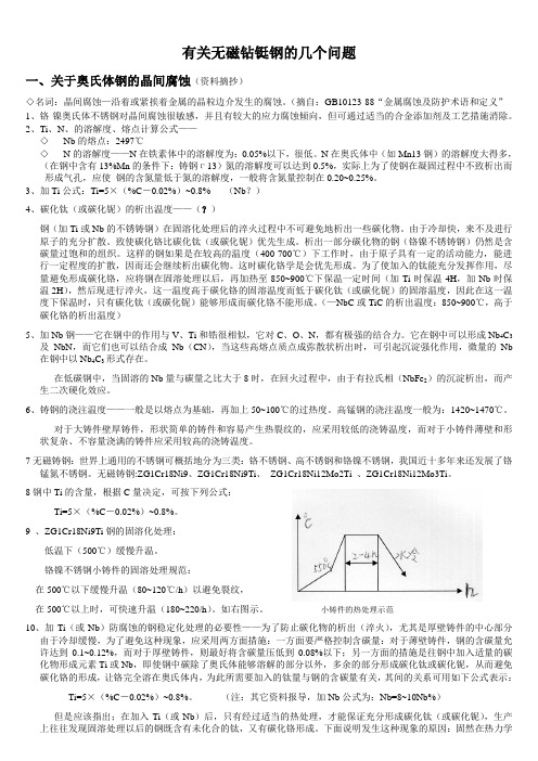
3、加Ti公式:Ti=5×(%C-0.02%)~0.8% (Nb?)4、碳化钛(或碳化铌)的析出温度——(?)钢(加Ti或Nb的不锈铸钢)在固溶化处理后的淬火过程中不可避免地析出一些碳化物。
由于冷却快,来不及进行原子的充分扩散。
致使碳化铬比碳化钛(或碳化铌)优先生成。
析出一部分碳化物的钢(铬镍不锈铸钢)仍然是含碳量过饱和的组织。
这样的钢如果是在较高的温度(400-700℃)下工作时,由于原子具有一定的活动能力,能进行一定程度的扩散,因而还会继续析出碳化物。
这时碳化铬学是会优先形成。
为了使加入的钛能充分发挥作用,尽量避免形成碳化铬,应将钢在固溶处理以后,再加热至850~900℃下保温一定时间(加Ti时保温4H,加Nb时保温2H),然后现进行淬火,这一温度高于碳化铬的固溶温度而低于碳化钛(或碳化铌)的固溶温度,因此在这一温度下保温时,只有碳化钛(或碳化铌)能够形成而碳化铬不能形成。
(—NbC或TiC的析出温度:850~900℃,高于碳化铬的析出温度)5、加Nb钢——它在钢中的作用与V、Ti和锆很相似,它对C、O、N,都有极强的结合力。
它在钢中可以形成Nb4C3及NbN,而它们也可以结合成Nb(CN),当这些高熔点质点成弥散状析出时,可引起沉淀强化作用,微量的Nb 在钢中以Nb4C3形式存在。
金属和合金的腐蚀 奥氏体及铁素体-奥氏体(双相)不锈钢晶间腐蚀试验方法

I C S77.060H25中华人民共和国国家标准G B/T4334 2020代替G B/T4334 2008金属和合金的腐蚀奥氏体及铁素体-奥氏体(双相)不锈钢晶间腐蚀试验方法C o r r o s i o no fm e t a l s a n da l l o y s T e s tm e t h o d s f o r i n t e r g r a n u l a r c o r r o s i o no fa u s t e n i t i c a n d f e r r i t i c-a u s t e n i t i c(d u p l e x)s t a i n l e s s s t e e l s[I S O3651-1:1998,D e t e r m i n a t i o no f r e s i s t a n c e t o i n t e r g r a n u l a r c o r r o s i o n o f s t a i n l e s s s t e e l s P a r t1:A u s t e n i t i c a n d f e r r i t i c-a u s t e n i t i c(d u p l e x)s t a i n l e s s s t e e l s C o r r o s i o n t e s t i nn i t r i c a c i dm e d i u mb y m e a s u r e m e n t o f l o s s i nm a s s (H u e y t e s t);I S O3651-2:1998,D e t e r m i n a t i o no f r e s i s t a n c e t o i n t e r g r a n u l a rc o r r o s i o no f s t a i n l e s s s t e e l s P a r t2:F e r r i t i c,a u s t e n i t i c a nd fe r r i t i c-a u s t e n i t i c(d u p l e x)s t a i n l e s s s t e e l s C o r r o s i o n t e s t i nm e d i a c o n t a i n i n g s u l f u r i c a c i d,M O D]2020-04-28发布2020-11-01实施国家市场监督管理总局前言本标准按照G B/T1.1 2009给出的规则起草㊂本标准代替G B/T4334 2008‘金属和合金的腐蚀不锈钢晶间腐蚀试验方法“㊂本标准与G B/T4334 2008相比,主要技术变化如下:将标准名称 金属和合金的腐蚀不锈钢晶间腐蚀试验方法 更改为 金属和合金的腐蚀奥氏体及铁素体-奥氏体(双相)不锈钢晶间腐蚀试验方法;对取样方法和尺寸进行了调整(见3.1,2008年版第3章);对敏化处理制度进行了调整(见3.2,2008年版第3章);对各试验方法的试验报告内容进行了调整(见第4章㊁第5章㊁第6章㊁第7章㊁第8章,2008年版第4章㊁第5章㊁第6章㊁第8章);废除了方法D 不锈钢硝酸-氢氟酸腐蚀试验方法(见2008年版第7章);方法E名称变更为 铜-硫酸铜-16%硫酸腐蚀试验方法 (见第7章,2008年版第8章);对方法E的弯曲参数进行了变更(见第7章,2008年版第8章);增加了方法F铜-硫酸铜-35%硫酸腐蚀试验方法(见第8章);增加了方法G 40%硫酸-硫酸铁腐蚀试验方法(见第9章);增加了对各种方法及其特点的说明(见附录C);增加了方法E㊁方法F㊁方法G的适用范围(见附录D)㊂本标准使用重新起草法修改采用I S O3651-1:1998‘不锈钢耐晶间腐蚀的测定第1部分:奥氏体及铁素体-奥氏体(双相)不锈钢含硝酸介质中的腐蚀试验“和I S O3651-2:1998‘不锈钢耐晶间腐蚀的测定第2部分:铁素体㊁奥氏体及铁素体-奥氏体(双相)不锈钢含硫酸介质中的腐蚀试验“㊂本标准与I S O3651-1:1998和I S O3651-2:1998相比在结构上有较多调整,附录A中列出了本标准与I S O3651-1:1998和I S O3651-2:1998的章条编号对照一览表㊂本标准与I S O3651-1:1998和I S O3651-2:1998相比存在技术性差异,这些差异涉及的条款已通过在其外侧页边空白位置的垂直单线(|)进行了标识,附录B给出了相应技术处差异及原因的一览表㊂本标准由中国钢铁工业协会提出㊂本标准由全国钢标准化技术委员会(S A C/T C183)归口㊂本标准起草单位:钢铁研究总院㊁山西太钢不锈钢股份有限公司㊁冶金工业信息标准研究院㊁安工腐蚀检测实验室科技(无锡)有限公司㊁酒泉钢铁(集团)有限责任公司㊁江苏申源集团有限公司㊁鞍钢股份有限公司㊁中冶检测认证有限公司㊂本标准主要起草人:朱玉亮㊁丰涵㊁冯超㊁李吉东㊁侯捷㊁薛俊鹏㊁刘森㊁翟健红㊁李倩㊁武裕民㊁宋志刚㊁任永秀㊁路民旭㊁惠恺㊁李风㊁贾元伟㊁林春来㊂本标准所代替标准的历次版本发布情况为:G B/T4334.1~G B/T4334.5 1984,G B/T4334.1~G B/T4334.5 2000;G B/T4334 2008㊂金属和合金的腐蚀奥氏体及铁素体-奥氏体(双相)不锈钢晶间腐蚀试验方法1范围本标准规定了奥氏体及铁素体-奥氏体(双相)不锈钢晶间腐蚀试验方法的试样㊁试验溶液㊁试验仪器和设备㊁试验条件和步骤㊁试验结果评定及试验报告等内容㊂本标准适用于检验奥氏体不锈钢及铁素体-奥氏体双相不锈钢(以下简称双相不锈钢)的晶间腐蚀倾向㊂包括以下试验方法:a)方法A:10%草酸浸蚀试验方法检验奥氏体不锈钢晶间腐蚀的筛选试验,试样在10%草酸溶液中电解浸蚀后,在显微镜下观察被浸蚀表面的金相组织,以判定是否需要进行方法B㊁方法C㊁方法E等长时间热酸试验㊂在不允许破坏被测结构件和设备的情况下,也可以作为独立的晶间腐蚀检验方法㊂b)方法B:50%硫酸-硫酸铁腐蚀试验方法将奥氏体不锈钢置于50%硫酸-硫酸铁溶液中经煮沸试验后,以腐蚀速率评定晶间腐蚀倾向㊂c)方法C:65%硝酸腐蚀试验方法将奥氏体不锈钢置于65%硝酸溶液中经煮沸试验后,以腐蚀速率评定晶间腐蚀倾向㊂d)方法E:铜-硫酸铜-16%硫酸腐蚀试验方法将奥氏体不锈钢㊁双相不锈钢置于铜-硫酸铜-16%硫酸溶液中经煮沸试验后,用弯曲法或金相法判定晶间腐蚀倾向㊂e)方法F:铜-硫酸铜-35%硫酸腐蚀试验方法将奥氏体不锈钢㊁双相不锈钢置于铜-硫酸铜-35%硫酸溶液中经煮沸试验后,用弯曲法或金相法判定晶间腐蚀倾向㊂f)方法G:40%硫酸-硫酸铁腐蚀试验方法将奥氏体不锈钢㊁双相不锈钢置于40%硫酸-硫酸铁溶液中经煮沸试验后,用弯曲法或金相法判定晶间腐蚀倾向㊂本标准的附录C以表格形式给出了各试验方法的特点,附录D给出了方法E㊁方法F㊁方法G的应用实例㊂本标准中各试验方法不适用于用来预测不锈钢在其他介质条件下的抗晶间腐蚀性能,也不适用于预测不锈钢对其他腐蚀形式(如点蚀㊁均匀腐蚀㊁应力腐蚀等)的耐蚀性能㊂2规范性引用文件下列文件对于本文件的应用是必不可少的㊂凡是注日期的引用文件,仅注日期的版本适用于本文件㊂凡是不注日期的引用文件,其最新版本(包括所有的修改单)适用于本文件㊂G B/T625化学试剂硫酸(G B/T625 2007,I S O6353-2:1983,N E Q)G B/T626化学试剂硝酸(G B/T626 2006,I S O6353-2:1983,N E Q)G B/T655化学试剂过硫酸铵G B/T665化学试剂无水合硫酸铜(Ⅱ)(硫酸铜)(G B/T665 2007,I S O6353-2:1983,N E Q) G B/T2100通用耐蚀钢铸件(G B/T2100 2017,I S O11972:2015,MO D)G B /T8170 数值修约规则与极限数值的表示和判定G B /T9854 化学试剂 二水合草酸(草酸)(G B /T9854 2008,I S O6353-2:1983,N E Q )3 试样3.1 取样及制备3.1.1 压力加工钢材的试样从同一炉号㊁同一规格和同一热处理批次的钢材中取样㊂3.1.2 铸件试样按G B /T2100规定,从同一炉号钢水浇注的试块中取样㊂含稳定化元素钛的钢种,在该炉号最末浇注的试块中取样㊂3.1.3 焊管试样从同一炉号㊁同一规格和同一热处理批次的焊管中取样㊂3.1.4 焊接试样从与产品钢材相同且焊接工艺也相同的试块上取样㊂3.1.5 试样表面宜接近产品原始表面状态㊂对于有焊接接头的试样应尽可能包括母材㊁热影响区以及焊接金属的表面㊂用方法A 判定凹坑组织时应检验断面㊂方法B ㊁方法C 试样尺寸及制备要求见表1,单个试样总表面积应不小于5c m 2,方法E ㊁方法F ㊁方法G 试样尺寸及制备要求见表2㊂3.1.6 试样采用机加工进行切取,如用剪切或其他方法时应通过切削或研磨的方法除去剪切的影响部分㊂3.1.7 方法A 试样被检查的表面应抛光,以便进行腐蚀和显微组织检验㊂3.1.8 方法B ㊁方法C ㊁方法E ㊁方法F ㊁方法G 试样上有氧化皮时,要通过切削或研磨的方式除去㊂需要敏化处理的试样,应在敏化处理后进行研磨㊂不能进行研磨的试样,可以进行酸洗,表面不能过酸洗㊂不能进行研磨或酸洗处理的试样,热处理时,表面不能氧化㊂3.1.9 方法B ㊁方法C ㊁方法E ㊁方法F ㊁方法G 试样切取及表面磨制过程中应防止表面过热,加工后的试样表面粗糙度R a 值一般应不大于0.8μm ㊂对无法精磨的试样,根据双方协议也可以采用其他表面粗糙度㊂表1 方法B ㊁方法C 试样尺寸及制备要求类 别厚度或直径amm 试样尺寸mm 长宽厚试样数量个说 明钢板㊁带(扁钢)ɤ330ʃ1020ʃ10 2沿轧制方向取样>330ʃ1020ʃ103~42沿轧制方向取样,一个试样从一面加工到试样厚度,另一个试样从另一面加工到试样厚度型钢㊁锻件 30ʃ1020ʃ103~42从截面中部沿纵向取样钢棒(钢丝)ɤ1030ʃ102>1030ʃ10ɤ20ɤ52从截面中部沿纵向取样无缝钢管<530ʃ10 2取整段管状试样5~1530ʃ102取半管状或舟形试样>1530ʃ10ɤ20壁厚<4mm 2壁厚ȡ4mm4一组(2个试样)从外壁加工到试样厚度,另一组(2个试样)从内壁加工到试样厚度G B /T 4334 2020表1(续)类 别厚度或直径amm试样尺寸mm 长宽厚试样数量个说 明焊管ɤ330ʃ10管壁厚2取半管状或舟形试样,焊缝沿试样长度方向,位于试样中部,见图1㊂对于舟形试样,试样母材边缘至熔合线距离,两面均不小于10mm ,试样内外表面不进行加工,需敏化处理的试样可在敏化后进行除去氧化膜的表面处理㊂对大直径管亦可采用弧形试样,数量加倍,焊缝位于弧形试样中央,见图2>330ʃ103~44管壁厚度不小于4mm 时,一组(2个试样)从外壁加工到试样厚度,另一组(2个试样)从内壁加工到试样厚度;其他要求同上铸件 30ʃ10ɤ20 2焊条 30ʃ1010ʃ5 2按图3取焊条试样堆焊焊条 30ʃ102按图4取堆焊焊条试样焊接接头(单焊缝) 30ʃ1020ʃ103~42焊缝位于中部,见图5焊接接头(交叉焊缝)30ʃ1020ʃ103~44焊缝交叉点位于试样中部,两个试样检验横焊缝,两个试样检验纵焊缝,见图6a对无缝钢管直径指外径㊂表2 方法E ㊁方法F ㊁方法G 试样尺寸及制备要求类 别厚度或直径amm 试样尺寸mm长宽厚试样数量个说 明钢板㊁带(扁钢)ɤ3ȡ5020ʃ102沿轧制方向取样,试验后每个试样均弯曲两个被检验面>3ȡ5020ʃ103~44沿轧制方向取样,两个试样从一面加工到试样厚度,另外两个试样从另一面加工到试样厚度;试验后各弯曲其相应的一个被检验面型钢㊁锻件 ȡ5020ʃ103~42 钢棒(钢丝)ɤ10ȡ502>10ȡ50ɤ20ɤ52从截面中部沿纵向取样;试验后每个试样均弯曲两个被检验面G B /T 4334 2020表2(续)类 别厚度或直径amm 试样尺寸mm长宽厚试样数量个说 明无缝钢管<5ȡ502取整段管状试样㊂采用弯曲法评定时内外壁都需检验,如内壁不能弯曲评定时,则用金相法评定;也可以采用压扁法评定5~15ȡ502取半管状或舟形试样,试验后每个试样均弯曲两个被检验面,也可取整管试样用压扁法评定>15ȡ50ɤ20壁厚<4mm 2壁厚ȡ4mm4一组(2个试样)从外壁加工到试样厚度,另一组(2个试样)从内壁加工到试样厚度,试验后各弯曲其相应的被检验面焊管ɤ3ȡ50管壁厚2取半管状或舟形试样,焊缝沿试样长度方向,位于试样中部,见图1;对于舟形试样,试样母材边缘至熔合线距离,两面均不小于10mm ,试样内外表面不进行加工,试验后每个试样均弯曲两个被检验面㊂需进行敏化处理的试样可在敏化后进行除去氧化膜的表面处理㊂对于大直径管亦可采用弧形试样,数量加倍,焊缝位于弧形试样中央㊂如图2所示,弯曲时,焊缝熔合线位于弯曲中心>3ȡ50 3~44管壁厚度大于4mm 时,一组(2个试样)从外壁加工到试样厚度,另一组(2个试样)从内壁加工到试样厚度,未加工面位于弯曲外侧;其他要求同上铸件 ȡ50ɤ20 4两个试样做试验,两个试样留做空白弯曲焊条ȡ5010ʃ5 2按图3取焊条试样,试验后每个试样均弯曲两个被检验面堆焊焊条 ȡ50 2按图4取堆焊焊条试样,试验后每个试样均弯曲两个被检验面焊接接头(单焊缝) ȡ5020ʃ103~42焊缝位于中部,试验后弯曲其相应的一个检验面,取样见图5焊接接头(交叉焊缝)ȡ5020~353~44焊缝交叉点位于试样中部,两个试样检验横焊缝,两个试样检验纵焊缝,试验后弯曲其相应的一个被检验面,取样见图6如因试样尺寸有限无法对同一试样的两个被检验面进行弯曲,则可取两个试样,分别弯曲两个试样的不同检验面,作为代替试验㊂同时,取样时标记出两个试样的检测面㊂ a对无缝钢管直径指外径㊂G B /T 4334 2020单位为毫米图1焊管舟形试样取样单位为毫米图2焊管弧形试样取样单位为毫米注:采用与焊条相应钢号的钢板㊂图3焊条试样取样G B/T4334 2020单位为毫米注:基层板用与焊条相应钢号的钢板,试样长度方向沿着施焊方向㊂图4堆焊焊条试样取样单位为毫米说明:1 弃去;2 焊接试样;3 焊板;4 弃去㊂图5单焊缝取样G B/T4334 2020单位为毫米说明:1焊接试样;2焊接试样;3焊板㊂图6 交叉焊缝取样3.2 试样的敏化处理3.2.1 对于超低碳不锈钢(碳含量不大于0.030%)和稳定化不锈钢(添加钛或铌),在评价其本征晶间腐蚀敏感性时,试验前应对试样进行敏化处理,试样的敏化制度由供需双方协商确定㊂对于奥氏体不锈钢,推荐的敏化制度为650ħʃ10ħ,保温2h ,空冷㊂对于双相不锈钢推荐的敏化制度为700ħʃ10ħ,30m i n ,水冷;也可采用650ħʃ10ħ,10m i n,水冷㊂3.2.2 对于其他的不锈钢,试样是否需要敏化处理和采取何种敏化处理制度,由产品标准或供需双方协商确定㊂3.2.3 焊接试样一般以焊后状态进行试验㊂对焊后还要经过350ħ以上热加工的焊接件,试样应在焊后进行敏化处理㊂敏化处理制度由供需双方协商㊂3.2.4 试样的敏化处理应在研磨前进行㊂敏化前和试验前应用适当的溶剂或洗涤剂(非氯化物)对试样进行除油并干燥㊂4 方法A 10%草酸浸蚀试验方法4.1 试验溶液4.1.1 将100g 符合G B /T9854的优级纯草酸溶解于900m L 蒸馏水或去离子水中,配制成10%草酸溶液㊂4.1.2 对含钼钢在难以出现阶梯组织时,可以用100g 符合G B /T655的分析纯过硫酸铵溶解于900m L 蒸馏水或去离子水中,配制成10%的过硫酸铵溶液代替10%的草酸溶液㊂G B /T 4334 20204.2试验仪器和设备4.2.1供浸蚀试验用的直流电源㊁可变电阻器㊁选用适当量程的电流表(精度0.5级)㊂4.2.2阴极为奥氏体不锈钢制成的钢杯或表面积足够大的不锈钢钢片,阳极为试样,如用不锈钢钢片作阴极时要采用适当形状的夹具,使试样保持于试验溶液中,浸蚀电路见图7㊂4.3试验条件和步骤4.3.1把浸蚀试样作阳极,以不锈钢钢杯或不锈钢钢片作为阴极,倒入10%草酸溶液,接通电流㊂阳极电流密度为1A/c m2,浸蚀时间90s,浸蚀溶液温度20ħ~50ħ㊂用10%过硫酸铵浸泡时,电流密度为1A/c m2,浸蚀时间5m i n~10m i n㊂4.3.2试样浸蚀后,用流水洗净,干燥㊂在金相显微镜下观察试样的全部浸蚀表面,放大倍数为200倍~500倍,根据表3㊁表4和图8~图14判定组织的类别㊂4.3.3每次试验使用新的溶液㊂4.4浸蚀组织的分类4.4.1显示晶界形态浸蚀组织的分类见表3㊂4.4.2显示凹坑形态浸蚀组织的分类见表4㊂4.4.310%草酸浸蚀试验与其他试验方法的关系见表5㊁表6㊂单位为毫米a)大试样用b)小试样用图7电解浸蚀装置图G B/T4334 2020单位为毫米c)不锈耐酸钢容器说明:1 不锈钢容器;2 试样;3 直流电源;4 变阻器;5 电流表;6 开关㊂图7(续)表3晶界形态的分类类别名称组织特征一类阶梯组织晶界无腐蚀沟,晶粒间呈台阶状;见图8二类混合组织晶界有腐蚀沟,但没有一个晶粒被腐蚀沟包围;见图9三类沟状组织晶界有腐蚀沟,个别或全部晶粒被腐蚀沟包围;见图10四类游离铁素体组织铸钢件及焊接接头晶界无腐蚀沟,铁素体被显现;见图11五类连续沟状组织铸钢件及焊接接头,沟状组织很深,并形成连续沟状组织;见图12表4凹坑形态的分类类别名称组织特征六类凹坑组织Ⅰ浅凹坑多,深凹坑少的组织;见图13七类凹坑组织Ⅱ浅凹坑少,深凹坑多的组织;见图14图8阶梯组织(一类)500ˑ图9混合组织(二类)500ˑ图10沟状组织(三类)500ˑ图11游离铁素体组织(四类)250ˑ图12连续沟状组织(五类)250ˑ说明:1 深凹坑;2 浅凹坑㊂图13凹坑组织(六类)500ˑ图14凹坑组织(七类)500ˑ表5筛选试验与其他试验方法的关系类别压力加工试样铸件㊁焊接试样方法B方法C方法E方法F方法G方法B方法C方法E方法F方法G一类ˑˑ ˑ 二类ˑˑ ˑ 三类ʻʻ ʻ 四类 ˑˑ ˑˑˑˑˑ五类 ʻʻ ʻʻʻʻʻ六类ˑˑˑˑˑˑˑˑˑˑ七类ˑʻˑˑˑˑʻˑˑˑ注:ˑ表示不必做其他方法试验;ʻ表示要做其他方法试验; 表示不做该试验㊂表6方法A与热酸试验的关系热酸试验用10%草酸浸蚀试验,判定是否需要做热酸试验的不锈钢钢种用热酸试验检验铬碳化物或σ相与不锈钢种的关系方法B 06C r19N i10㊁022C r19N i1006C r17N i12M o2㊁022C r17N i12M o206C r18N i12M o2C u2022C r18N i14M o2C u206C r19N i13M o3㊁022C r19N i13M o3铬碳化物:06C r19N i10㊁022C r19N i1006C r17N i12M o2㊁022C r17N i12M o206C r18N i12M o2C u2㊁022C r18N i14M o2C u206C r19N i13M o3㊁022C r19N i13M o3方法C06C r19N i10㊁022C r19N i10铬碳化物:06C r19N i10㊁022C r19N i10铬碳化物与σ相:06C r18N i12M o2C u2㊁022C r18N i14M o2C u2 022C r17N i12M o2㊁06C r17N i12M o206C r19N i13M o3㊁022C r19N i13M o3㊁06C r18N i11T i 06C r18N i11N b表6(续)热酸试验用10%草酸浸蚀试验,判定是否需要做热酸试验的不锈钢钢种用热酸试验检验铬碳化物或σ相与不锈钢种的关系方法E 06C r18N i9㊁022C r19N i1006C r17N i12M o2㊁022C r17N i12M o206C r18N i12M o2C u2022C r18N i14M o2C u2㊁06C r19N i13M o3022C r19N i13M o3㊁06C r18N i10T i06C r18N i10T i铬碳化物:06C r18N i9㊁022C r19N i10㊁06C r17N i12M o2022C r17N i12M o2㊁06C r18N i12M o2C u2022C r18N i14M o2C u2㊁06C r19N i13M o3022C r19N i13M o3㊁06C r18N i10T i0C r18N i10T i4.5试验报告试验报告应包括以下内容:a)本标准编号及名称;b)试验方法;c)试样的名称及试验面积尺寸;d)电流密度;e)浸蚀时间和温度;f)浸蚀后的金相照片;g)判定结果㊂5方法B50%硫酸-硫酸铁腐蚀试验方法5.1试验溶液5.1.1将236m L符合G B/T625的优级纯硫酸缓缓加入盛有400m L蒸馏水的锥形瓶中配制成50% (49.4%~50.9%)硫酸溶液(注意防止暴沸)㊂5.1.2称取25g水合硫酸铁[F e2(S O4)3㊃x H2O],硫酸铁约75%(质量分数)加入上述硫酸溶液中㊂5.1.3为防止暴沸,推荐将纯三氧化二铝制成的碎屑加入试验溶液中㊂5.1.4连接烧瓶与冷凝器并通上冷却水,加热使溶液沸腾,直到硫酸铁全部溶解㊂5.1.5操作时应保护好眼睛并佩戴防护手套㊂将试验用烧瓶置于通风柜中㊂5.2试验仪器和设备5.2.1推荐使用容量为1L带回流冷凝器的磨口锥形烧瓶㊂5.2.2使试验溶液能保持微沸状态的加热装置㊂5.2.3精度不低于0.02mm的游标卡尺㊂5.3试验条件和步骤5.3.1测量试样的尺寸,计算试样的表面积(取3位有效数字)㊂5.3.2试验前对试样进行称重(精确到1m g)㊂5.3.3溶液量按试样表面积计算,其量不少于20m L/c m2㊂5.3.4试样放在试验溶液中用玻璃支架保持于溶液中部,连续煮沸120h㊂每一容器中只放一个试样㊂5.3.5通常试验中不需要更换溶液,但要注意尽可能减少溶液的挥发㊂溶液开始沸腾时,在瓶体上标记液面位置,以检查溶液的挥发程度㊂如果液面位置发生了明显变化,则需要更换新的溶液并使用新的试样或重新打磨过的试样进行试验㊂5.3.6 试验中间若有需要,可取出试样进行称量,然后继续试验㊂5.3.7 试验期间,试验溶液应无明显颜色变化㊂若试样腐蚀过快,甚至由此导致溶液颜色明显由黄色变为绿色,则需要在试验过程中加入更多的硫酸铁㊂通过中间称量,如果试样总质量的消耗达到了2g,则试样质量每消耗1g 需要加入10g 硫酸铁㊂5.3.8 试验后取出试样,在流水中用软刷子刷掉表面的腐蚀产物,洗净㊁干燥㊁称重㊂5.3.9 每次试验用新的溶液㊂5.4 试验结果评定以腐蚀速率评定试验结果,腐蚀速率按式(1)计算,单位为克每平方米每小时[g/(m 2㊃h )],计算结果按G B /T8170进行数值修约,修约到小数点后第二位㊂腐蚀速率=W 前-W 后S ˑt(1)式中:W 前 试验前试样质量,单位为克(g);W 后 试验后试样质量,单位为克(g);S 试样总面积,单位为平方米(m 2);t试验时间,单位为小时(h)㊂5.5 试验报告试验报告应包括以下内容:a ) 本标准编号及名称;b ) 试验方法;c ) 试样的名称及尺寸面积;d ) 如经过敏化处理应记录敏化处理制度;e ) 试验时间;f ) 试验前后试样质量;g ) 试样的腐蚀速率[g/(m 2㊃h )]㊂6 方法C 65%硝酸腐蚀试验方法6.1 试验溶液将符合G B /T626的优级纯硝酸用蒸馏水或去离子水配制成为65.0%ʃ0.2%(质量分数)的硝酸溶液(ρ20=1.40g /m L )㊂6.2 试验仪器和设备同5.2㊂6.3 试验条件和步骤6.3.1 测量试样的尺寸㊁计算试样的表面积(取3位有效数字)㊂6.3.2 试验前对试样进行称重(精确到1m g)㊂6.3.3 试样放在试验溶液中用玻璃支架保持于溶液中部㊂溶液量按试样表面积计算,其量不少于20m L/c m2㊂每周期应用新的试验溶液㊂每一容器中只放一个试样㊂6.3.4对于常规检验,在同一容器中可试验两个试样,但这两个试样应是同一规格㊁同一炉号和同一热处理制度,如果两个试样中有一个未能通过试验,按6.3.3重新试验㊂6.3.5试验5个周期,每周期连续煮沸48h㊂试验后取出试样,在流水中用软刷子刷掉表面的腐蚀产物,洗净㊁干燥㊁称重㊂根据供需双方协商,也可使用其他周期次数进行试验㊂6.3.6每次试验用新的溶液㊂6.4试验结果评定以腐蚀速率评定试验结果,腐蚀速率按式(1)计算㊂计算结果按G B/T8170进行数值修约,修约到小数点后第二位㊂然后计算各个周期的平均值㊂焊接试样发现刀状腐蚀即为具有晶间腐蚀倾向,如有异议,可用金相法判定㊂6.5试验报告试验报告应包括下列内容:a)本标准编号及名称;b)试验方法;c)试样的名称及尺寸面积;d)如经过敏化处理应记录敏化处理制度;e)试验时间;f)试验前后试样质量;g)每个试样各周期的试验时间长及腐蚀速率[g/(m2㊃h)],以及各周期腐蚀速率的平均值㊂7方法E铜-硫酸铜-16%硫酸腐蚀试验方法7.1试验溶液将100g符合G B/T665的分析纯硫酸铜(C u S O4㊃5H2O)溶解于700m L蒸馏水或去离子水中,再加入100m L符合G B/T625的优级纯硫酸,用蒸馏水或去离子水稀释至1000m L,配制成16%硫酸-硫酸铜溶液㊂7.2试验仪器和设备7.2.1推荐使用容量为1L带回流冷凝器的磨口锥形烧瓶㊂7.2.2使试验溶液能保持微沸状态的加热装置㊂7.3试验条件和步骤7.3.1试验前将试样用适当的溶剂或洗涤剂(非氯化物)除油并干燥㊂7.3.2在烧瓶底部铺一层纯度不小于99.5%的铜屑㊁铜粒或碎铜片,然后放置试样㊂保证每个试样与铜屑接触的情况下,同一烧瓶中允许放置一个以上同一钢种的试样,试样之间要互不接触㊂注:使用碎铜片时注意防止溶液暴沸㊂7.3.3试验溶液量按试样表面积计算,其量不少于8m L/c m2㊂试验溶液应高出试样20mm以上㊂每次试验都应使用新的试验溶液㊂7.3.4将烧瓶放在加热装置上,通以冷却水,加热试验溶液,使之保持微沸状态㊂试验连续20hʃ5h,如有争议,应采用20h㊂7.3.5试验后取出试样,洗净㊁干燥㊁弯曲㊂7.3.6每次试验用新的溶液㊂7.4试验结果评定7.4.1压力加工件试样弯曲角度为180ʎ㊂铸钢件㊁焊管和焊接件弯曲角度不小于90ʎ,焊管舟形试样沿垂直焊缝方向进行弯曲,焊接接头沿熔合线进行弯曲㊂对于低韧性的材料,可以采用一个未经试验的试样确定其不发生开裂的最大弯曲角度,以此作为弯曲试验的弯曲角度㊂7.4.2对于压力加工件,试样弯曲用的压头直径应不大于试样厚度的2倍;对于铸钢件㊁焊管和焊接件,试样弯曲用的压头直径应不大于试样厚度的4倍㊂7.4.3对于直径不大于15mm的整管试样,采用压扁试验评定时,两压板之间的距离H,按式(2)计算:H=1.09D t0.09D+t (2)式中:t 试样厚度,单位为毫米(mm);D 试样外径,单位为毫米(mm)㊂7.4.4弯曲后的试样在10ˑ放大镜下观察试样表面是否有因晶间腐蚀而产生的裂纹㊂从试样的弯曲部位棱角产生的裂纹,以及不伴有裂纹的滑移线㊁皱纹和表面粗糙等都不能认为是晶间腐蚀而产生的裂纹㊂7.4.5试样不能进行弯曲评定或弯曲的裂纹难以判定时,则采用金相法㊂金相磨片应取自试样的非弯曲部位(焊接接头和焊管除外),经浸蚀后(不得过腐蚀),在显微镜下观察(150ˑ~500ˑ),允许的晶间腐蚀深度由供需双方协商确定㊂注:如果怀疑裂纹是由于弯曲产生的裂纹,可对一未经过腐蚀试验的试样进行同样的弯曲,弯曲后进行比较,便可以认定在腐蚀试验试样上看到的裂纹是否是由于晶间腐蚀造成的㊂7.5试验报告试验报告应包括以下内容:a)本标准编号及名称;b)试验方法;c)试样的名称及尺寸面积;d)如经过敏化处理应记录敏化处理制度;e)试验时间;f)试样弯曲角度及10ˑ放大镜观察后,晶间腐蚀倾向结果;g)如果用金相法判定时,应记录放大倍数及晶间腐蚀深度㊂8方法F铜-硫酸铜-35%硫酸腐蚀试验方法8.1试验溶液将250m L符合G B/T625的优级纯硫酸加入750m L蒸馏水或去离子水中,再加入110g符合G B/T665的分析纯硫酸铜(C u S O4㊃5H2O),配制成35%硫酸-硫酸铜溶液㊂8.2试验仪器和设备同7.2㊂8.3试验条件和步骤8.3.1试验前将试样用适当的溶剂或洗涤剂(非氯化物)除油并干燥㊂8.3.2在烧瓶底部铺一层纯度不小于99.5%的铜屑㊁铜粒或碎铜片,然后放置试样㊂保证每个试样与铜屑接触的情况下,同一烧瓶中允许放置一个以上同一钢种的试样,试样之间要互不接触㊂注:使用碎铜片时注意防止溶液暴沸㊂8.3.3试验溶液量按试样表面积计算,其量不少于10m L/c m2㊂试验溶液应高出试样20mm以上㊂每次试验都应使用新的试验溶液㊂8.3.4将烧瓶放在加热装置上,通以冷却水,加热试验溶液,使之保持微沸状态㊂试验连续20hʃ5h,如有争议,应采用20h㊂8.3.5试验后取出试样,洗净㊁干燥㊁弯曲㊂8.3.6每次试验用新的溶液㊂8.4试验结果评定8.4.1试样弯曲角度不小于90ʎ,焊管舟形试样沿垂直焊缝方向进行弯曲,焊接接头沿熔合线进行弯曲㊂对于低韧性的材料,可以采用一个未经试验的试样确定其不发生开裂的最大弯曲角度,以此作为弯曲试验的弯曲角度㊂8.4.2对于压力加工件,试样弯曲用的压头直径应不大于试样厚度的2倍;对于铸钢件㊁焊管和焊接件,试样弯曲用的压头直径应不大于试样厚度的4倍㊂8.4.3对于直径不大于15mm的整管试样,采用压扁试验评定时,两压板之间的距离H,按式(2)计算㊂8.4.4弯曲后的试样在10ˑ放大镜下观察弯曲试样外表面是否有因晶间腐蚀而产生的裂纹㊂从试样的弯曲部位棱角产生的裂纹,以及不伴有裂纹的滑移线㊁皱纹和表面粗糙等都不能认为是晶间腐蚀而产生的裂纹㊂8.4.5试样不能进行弯曲评定或弯曲的裂纹难以判定时,则采用金相法㊂金相磨片应取自试样的非弯曲部位(焊接接头和焊管除外),经浸蚀后(不得过腐蚀),在显微镜下观察(150ˑ~500ˑ),允许的晶间腐蚀深度由供需双方协商确定㊂注:如果怀疑裂纹是由于弯曲产生的裂纹,可对一未经过腐蚀试验的试样进行同样的弯曲,弯曲后进行比较,便可以认定在腐蚀试验试样上看到的裂纹是否是由于晶间腐蚀造成的㊂8.5试验报告同7.5㊂9方法G40%硫酸-硫酸铁腐蚀试验方法9.1试验溶液将280m L符合G B/T625的优级纯硫酸加入720m L蒸馏水或去离子水中,再称取25g水合硫酸铁[F e2(S O4)3㊃x H2O],硫酸铁约75%(质量分数)加入上述硫酸溶液中,配制成40%硫酸-硫酸铁溶液㊂9.2试验仪器和设备同7.2㊂。
- 1、下载文档前请自行甄别文档内容的完整性,平台不提供额外的编辑、内容补充、找答案等附加服务。
- 2、"仅部分预览"的文档,不可在线预览部分如存在完整性等问题,可反馈申请退款(可完整预览的文档不适用该条件!)。
- 3、如文档侵犯您的权益,请联系客服反馈,我们会尽快为您处理(人工客服工作时间:9:00-18:30)。
奥氏体不锈钢晶间腐蚀试验方法
一、试验方法:奥氏体不锈钢10%草酸浸蚀试验方法
试样在10%的草酸溶液中电解浸蚀后,在显微镜下观察浸蚀表面的金相组织。
二、试样
1、取样及制备:
1)焊接试样从与产品钢材相同而且焊接工艺也相同的试块上取样,试样应包括母材、热影响区以及焊接金属的表面;
2)取样方法:原则上用锯切,如用剪切方法时应通过切削或研磨的方法除去剪切影响部分;3)试样被检查的表面应抛光,以便进行腐蚀和显微组织检验;
2、试样的敏化处理
1)敏化前和试验前试样用适当的溶剂或洗涤剂(非氯化物)除油并干燥;
2)焊接试样直接以焊后状态进行试验。
对焊后还要经过350℃以上热加工的焊接件,试样在焊后还应进行敏化处理。
试样的敏化处理在研磨前进行,敏化处理制度为650℃,保温1小时,空冷。
三、试验方法
1、试验溶液:将100克符合GB/T9854的优先级纯草酸溶解于900ml蒸馏水或去离子水中,
配置成10%草酸溶液;
2、实验仪器和设备:阴极为奥氏体不锈钢制成的钢杯或表面积足够大的钢片,阳极为试样,
如用钢片作阴极时要采用适当形状的夹具,使试样保持于试验溶液中,浸蚀电路如图1所示。
1——不锈钢容器
2——试样
3——直流电源
4——变阻器
5——电流表
6——开关
图1 电解浸蚀装置图
3、试验条件和步骤:
1)把浸蚀试样作阴极,以不锈钢杯或不锈钢片作为阴极,倒入10%草酸溶液,接通电流。
阳极电流密度为1A/cm2,浸蚀时间为90s,浸蚀溶液温度为20℃~50℃。
2)试样浸蚀后,用流水洗净,干燥。
在金相显微镜下观察试样的全部浸蚀表面,放大倍数为200倍~500倍,根据表1、表2和图2~图8判定组织的类别。
3)每次试验使用新的溶液。
4、浸蚀组织的分类
1)显示晶界形态浸蚀组织的分类见表1;
2)显示凹坑形态浸蚀组织的分类见表2;
3)一类阶梯组织和二类混合组织是可接受的组织,其余为不可接受组织。
5、试验报告:
试验报告应包括以下内容:
1)试验的名称及试验面积尺寸;
2)电流密度;
3)浸蚀时间和温度;
4)浸蚀后的金相照片;
5)判定结果。
附:单焊缝取样示意图。