cam说明书
cad cam说明书

目录一、设计的目的二、设计的内容和要求三、轮式迷你起重机零件的创建1、移动轮零件1.1、底座1.2、垫片1.3、转向轴1.4、支架1.5、轮子2、起重臂零件2.1、起重臂一关节2.2、起重臂二关节2.3、起重臂三关节2.4、千斤顶外筒2.5、千斤顶内筒2.6、转轴2.7、电机基座2.8、电机2.9、吊钩2.10、滑轮及轴3.工作台3.1、工作台模型3.2、移动论及工作台连接螺钉3.2、连接垫片四、装配1、移动轮装配2、起重臂装配3、起重机总装配五、运动仿真六、总结一、设计的目的通过本次课程设计,使学生全面地、系统地了解和掌握cad/cam技术的基本内容和基本知识。
通过本次设计实践,培养学生分析和解决生产技术问题的能力,使学生初步掌握现代机械设计设计方法与手段,并巩固、深化已学得的理论知识,进一步培养学生熟悉PROE三维实体建模和运用有关图册、图表等技术资料的能力,训练学生识图、制图、运用现代设计方法的基本技能。
同时培养学生的创新意识、工程意识和动手能力。
二、设计的内容和要求1、设计内容:设计创建10个零件以上(含10个)的装配体三维模型2、要求:2.1、生活或生产中有实际使用价值的实物;2.2、要求有螺纹连接;2.3、有运动仿真;2.4、写出设计说明书。
3、料提交:3.1、模型电子文档3.2、说明书纸质材料(封面统一格式,A4纸打印)三、轮式迷你起重机零件的创建1、移动轮零件1.1、底座选取新建命令,创建一新的模板,选取类型组中的零件和子类型中的实体。
使用拉伸命令创建一个长度为95、宽度为66、厚度为4的实体,执行:““插入、拉伸、位置、定义、选取草绘面”,进入草绘界面进行如图所示的草绘,再打勾确定,拉伸深度输入4,如图所示:绘制轴孔:利用旋转工具切除实体。
执行“插入、旋转、位置、定义、选取草绘面”,进入草绘界面进行如图所示的草绘:打勾确认,点去除材料实行材料切除。
执行“插入、旋转、位置、定义、选取草绘面”,进入草绘界面进行如图所示的草绘:打勾确认,点去除材料实行材料切除。
cam-e16-en900说明书

cam-e16-en900说明书
一、使用注意
1、非专业人员不得拆卸、安装本控制器以防麻烦发生。
2、不可损坏、厌迫或放置重物在电继在线,会导致漏电或火灾。
3、控制器外部配线要安装短路保护的断路器和其他安全措施。
4、不可触摸控制器内部,会导致触电。
二、环境注意
1、切勿于下列的地点操作控制系统及放置、储存控制器。
2、环境温度低于0℃或高于55℃的场所。
3、环境湿度低于10%或高于90%的场所。
4、有任何腐触性或可燃气体的场所。
5、灰鹿、盐空气、或金属粉末过多的场所。
三、安装注意
1、勿靠近吸气和排气处并小心勿进入异物,以防火灾和麻烦发生。
2、要将控制器固定在安装孔上,以防滑落、操作不当和受损。
四、操作注意
1、机器运转时勿切断控制器主电力开关,以防受损。
2、电力中断恢复后,有突然运转的可能性,所以不可靠近机器,以防受伤。
3、请检查并确认电力供应情况正常,以防麻烦发生。
4、错误侦测的同时,解决问题后,保持安全状熊,然后解除错误,再次开始运转,以防受损。
五、保养和检修注意
1、不要自己拼凑或修理,以防触电,火炎或麻烦发生。
2、禁止在通雷时猜拆卸任何模组。
如果猜拆卸可能会造成严重的解雷或雷死的情事禁止在通电时接触任何端子。
如果接触可能会造成严重的触电或电死的情事。
植物(Plant)钙调素(CAM)ELISA试剂盒说明书

本试剂盒只能用于科学研究,不得用于医学诊断植物(Plant)钙调素(CAM)ELISA检测试剂盒使用说明书检测原理试剂盒采用双抗体一步夹心法酶联免疫吸附试验(ELISA)。
往预先包被钙调素(CAM)抗体的包被微孔中,依次加入标本、标准品、HRP标记的检测抗体,经过温育并彻底洗涤。
用底物TMB显色,TMB在过氧化物酶的催化下转化成蓝色,并在酸的作用下转化成最终的黄色。
颜色的深浅和样品中的钙调素(CAM)呈正相关。
用酶标仪在450nm 波长下测定吸光度(OD值),计算样品浓度。
样品收集、处理及保存方法1.样本不能含叠氮钠(NaN3),因为叠氮钠(NaN3)是辣根过氧化物酶(HRP)的抑制剂。
2.标本采集后尽早进行提取,提取按相关文献进行。
3.植物萃取液或其它相关样本:请1000x g离心20分钟,取上清即可检测。
4.保存:如果样本收集后不及时检测,请按一次用量分装,冻存于-20℃,避免反复冻融,在室温下解冻并确保样品均匀地充分解冻。
自备物品1.酶标仪(450nm)2.高精度加样器及枪头:0.5-10uL、2-20uL、20-200uL、200-1000uL3.37℃恒温箱操作注意事项1.试剂盒保存在2-8℃,使用前室温平衡20分钟。
从冰箱取出的浓缩洗涤液会有结晶,这属于正常现象,水浴加热使结晶完全溶解后再使用。
2.实验中不用的板条应立即放回自封袋中,密封(低温干燥)保存。
3.浓度为0的S0号标准品即可视为阴性对照或者空白;按照说明书操作时样本已经稀释5倍,最终结果乘以5才是样本实际浓度。
4.严格按照说明书中标明的时间、加液量及顺序进行温育操作。
5.所有液体组分使用前充分摇匀。
试剂盒组成名称96孔配置48孔配置备注微孔酶标板12孔×8条12孔×4条无标准品0.3mL*6管0.3mL*6管无样本稀释液6mL3mL无检测抗体-HRP10mL5mL无20×洗涤缓冲液25mL15mL按说明书进行稀释底物A6mL3mL无底物B6mL3mL无终止液6mL3mL无封板膜2张2张无说明书1份1份无自封袋1个1个无注:标准品(S0-S5)浓度依次为:0、10、20、40、80、160pg/mL试剂的准备20×洗涤缓冲液的稀释:蒸馏水按1:20稀释,即1份的20×洗涤缓冲液加19份的蒸馏水。
Logitech CAM540 用户手册说明书
CAM540 User ManualFederal Communications Commission StatementThis device complies with Part 15 of the FCC Rules. Operation issubject to the following two conditions: (1) This device may notcause harmful interference, and (2) this device must accept any interference received, including interference that may cause undesired operation.This equipment has been tested and found to comply with the limits for a Class B digital device, pursuant to Part 15 of the FCC Rules. These limits are designed to provide reasonable protection against harmful interference in a residential installation. This equipment generates uses and can radiate radio frequency energy and, if not installed and used in accordance with the instructions, may cause harmful interference to radio communications. However, there is no guarantee that interference will not occur in a particular installation. If this equipment does cause harmful interference to radio or television reception, which can be determined by turning the equipment off and on, the user is encouraged to try to correct the interference by one of the following measures:- Reorient or relocate the receiving antenna.- Increase the separation between the equipment and receiver.- Connect the equipment into an outlet on a circuit different from that to which the receiver is connected.- Consult the dealer or an experienced radio/TV technician for help.FCC Caution: Any changes or modifications not expressly approved by the party responsible for compliance could void the user's authority to operate this equipment.DISCLAIMERNo warranty or representation, either expressed or implied, is made with respect to the contents of this documentation, its quality, performance, merchantability, or fitness for a particular purpose. Information presented in this documentation has been carefully checked for reliability; however, no responsibility is assumed for inaccuracies. The information contained in this documentation is subject to change without notice.In no event will AVer Information Inc. be liable for direct, indirect, special, incidental, or consequential damages arising out of the use or inability to use this product or documentation, even if advised of the possibility of such damages.TRADEMARKS“AVer” is a trademark owned by AVer In formation Inc. Other trademarks used herein for description purpose only belong to each of their companies. COPYRIGHT©2018 AVer Information Inc. All rights reserved.All rights of this object belong to AVer Information Inc. Reproduced or transmitted in any form or by any means without the prior written permission of AVer Information Inc. is prohibited. All information or specifications are subject to change without prior notice.NOTICESPECIFICATIONS ARE SUBJECT TO CHANGE WITHOUT PRIOR NOTICE. THE INFORMATION CONTAINED HEREIN IS TO BE CONSIDERED FOR REFERENCE ONLY.ContentsPackage Contents (1)Optional Accessories (1)Product Introduction (2)Camera (2)Remote Control (3)Installation (5)Device Connection (5)Wall Mount Installation (6)Celling Mount and Switch Box Installation (9)Secure USB Cable (11)Pan and Tilt Angle (11)RS232 Connection (12)Make a Video Call (13)AVer PTZApp (14)Install AVer PTZApp (14)Use AVer PTZApp (14)Set the Camera Number (19)Hotkey Control (20)Home / Sleep Position (21)ADDR / Protocol/Baud Rate (21)OpenGL (21)Install EZLive (22)Use AVer EZLive (22)Package Contents* The power cord will vary depending on the standard power outlet of the country where it is sold. Optional AccessoriesProduct IntroductionCamera(6)(7)(1)(2)(4)(3)(5)Remote Controller1. Camera select One remote can control up to 3 AVer VC/CAM. Use AVer PTZAppsets number associated with each camera, select which camerayou like to control on the remote.2. Camera direction control Use the direction button on the remote to control the direction ofthe camera. Press the direction button to move the camera orpress and hold for continuous pan or tilt.3. SmartFrameOne-click automatic FOV adjustment to fit all participants.4. OSD menu** Press to bring out OSD menu.5. Zoom in/Zoom out Increase/Decrease the camera zoom.6. Preset⏹Press to get back to “home” position that user has set.⏹To save the camera at the desired position, press and hold thepreset button until the "saved message" is displayed on thePTZApp video screen or other video apps. Select presetposition button 0 to 9 to save.⏹Press “preset” + “preset position button” (0 ~ 9) will move thecamera to the saved position.7. Preset position Preset position button is used in conjunction with the Preset buttonto save positions. There are a total of 0 to 9 saves.Press preset button and then press 0~9 to go to the savedposition.8. Call/answer*Answer a call or start a call.9. Enter** To confirm selection in OSD menu.10. Mute/UnmuteMute/Unmute the speakerphone.Speakerphone**11. Volume up/down**Adjust volume up or down.12. Far site camera control** Press the Far/Near button to control the far site camera for pan,tilt, or zoom functions.13. Hang up* End the call.* Function requires AVer PTZApp** Not support for CAM540InstallationDevice Connection1. Use USB cable to connect the CAM540 to your PC/laptop (refer to diagram above).2. Connect the power to the CAM540; power indicator will light up and camera head will rotate.3. Install AVer PTZApp on laptop or PC that is connected with CAM540. The app can be used toadjust and setup the parameters of the camera (refer to the section of AVer PTZApp)4. To make a call, run your video application (Skype TM, Microsoft ®Lync TM, Skype for Business,Google Hangouts TM, Cisco WebEx®, GoToMeeting TM, WebRTC, and etc.) select CAM540 as your video device.Wall Mount InstallationAccording to below figure to drill the hole on the wall where the user wants to mount the camera.1.2.3. Secure the screw to the camera. Don’t screw tight, leave some space for later installation.4. Install the camera to the wall mount bracket.5. Connect the necessary cables to the camera.[Note] You may use cable ties to organizer cables.6. Secure the camera with screws; please follow the order as figure shown to secure the camera.Celling Mount and Switch Box InstallationThe camera can be mounted on the celling, please refer the following steps.1. Secure the screw on to the camera. Don’t screw tight, leave some space for later installation.2. Place the camera to the wall mount bracket.3. Connect the necessary cables to the camera.[Note] You may use cable ties to organizer cables.4. Secure the camera with screws; please follow the order as figure shown to secure the camera.5. Refer to the figure shown which the holes to secure the wall mount bracket with camera to thecelling.For the switch box installation, refer to the figure shown to secure the wall mount bracket to the switch box. Then, refer to wall mount installation steps.Secure USB CableInstall the cable first and secure the cable.[Note] Make sure the cable is well connect to the connector on the camera before secure the cablePan and Tilt AngleRS232 ConnectionThrough the RS232 connection, the user can control the camera unit.Make a Video Call1. Make sure CAM540 and PC/laptop are well connected and power is on.2. Run your video application (Skype TM, Microsoft ®Lync TM, Google Hangouts TM, Cisco WebEx®,GoToMeeting TM, WebRTC, TrueConf, V-Cube, U-meeting and etc.) on your PC or laptop.3. Set the CAM540 camera as the primary camera for your video application (refer to your videoapplication user guide). You can now make your call.4. The CAM540 is a plug-and-play conference camera. The system requires no special drivers, butwe do recommend installing the AVer PTZApp for a better user experience. For information on how to install and use the AVer PTZApp, refer to the AVer PTZApp section in this user manual.AVer PTZAppInstall AVer PTZAppPlease go to /download-center to download the AVer PTZApp. After downloading, double-click on the file and follow the on-screen instructions to complete the installation.Use AVer PTZApp1. To run your video application, a plug-in request will be displayed on your video applicationinterface. Click on it to accept the plug-in; your video application can now be control by AVer PTZApp and remote control.2. During your video call, you can use the AVer PTZApp to pan, tilt and zoom the camera in/out andenable/disable the backlight feature.3. For the first time use, you can check the connection, camera, and setup the camera’s parameters .Each function will be described below:a bc d efgh ia. Currently selected device: This field displays currently selected VC or CAM device controlled byPTZApp. If you have more than one AVer VC or CAM devices connected to this PC/Mac PTZApp is running, you can click on the drop-down list to select other AVer VC or CAM device.b. Function icon: Click it to switch to the functio n’s page.- PTZ: To control the camera direction, zoom in and out, and to enable/disable the backlight compensation during your video call.- Settings: To setup parameters of the camera. Click the Save button to save all settings. To change all the settings, back to the default values, click the Factory Default button.[Note] For USB Data Transfer Mode, please select mode in Mac OS and Windows as: ✓For Mac OS: isochronous mode✓For Windows: Bulk mode- Diagnostic Utility: To display the S/W and F/W version and the devices connection status.You can also update the firmware of the camera.c. Minimize: Minimize the app to system tray. To quit the application, right-click the icon on thesystem tray and select “Quit”.d. : Click icon will launch the browser and connect to the AVer PTZApp web page.e. (Camera): Click it to view the camera live view. Click the camera icon again to close thecamera live view. If the live video did not appear, please check the camera and the laptop/PC connection to make sure all are corrected and well connected.Normal Un-normalf. Connection diagnostic: Display devices connection status. If the AVer PTZApp has detectedthat camera and laptop/PC are not connected well, the diagram will disp lay an “?” on the camera to indicate the connection has a problem. If the camera is in use by another application, it will display “Can’t start video” warning.g. Test Camera: Click the “Test Camera” to check the camera video display status. You can adjustthe camera direction and view of the zoom in/out. To leave the page, click the Abort Diagnostic button.h. Update Now: Allows the user to update the CAM540 camera’s firmware.1. Click” Update Now”.2. A dialog will display the current firmware version and available new firmware version (internetconnection is required).3. To auto update, click “Auto Update” and update pro cess will start. The new firmware will bedownloaded first; then, the new firmware will be uploaded to the camera.[Note] Please make sure camera, power, and laptop/PC are all well connected and stayconnected during the entire process.4. To update the firmware manually, click “Manual Update” and locate the new firmware to startthe process.i. Troubleshooting: collect more system information for troubleshooting before you contact AVertechnical support.Set the Camera NumberWith multiple cameras connection, users can set each camera to buttons 1 to 3 on the remote control.1. If PTZApp detects computer connects to multiple VC/CAM, you can select which camera you liketo control through the dropdown list.2. Next, Click Change Binding button.13. Select which camera number of remote control it maps to.4. Click Save to save settings. To un-save the settings, click Abort.2 3Hotkey ControlEnable hotkey control to use keyboard control camera ’s movement and backlight. 1. Select “Settings ”2.Set Hotkey Control to “On ”.3.A hotkey description as below figure shown:1Home / Sleep PositionHome Position: There are three options: Last operating position/Factory central position/ Preset 0 Sleep Position: There are two options -- Factory sleep position/ Preset 9If the camera idles for more than 3 minutes, it will enter sleep mode.ADDR / Protocol/Baud RateThese settings are related to RS232 functions. Please choose the corresponding value while connecting with external control panels.OpenGLThe default setting is Off. If your PC has installed OpenGL, you can get better frame rate and smoother video quality by turn on it. If your PC is without OpenGL, it will cause video display problem after enable it.Install EZLivePlease go to /download-center to download the AVer EZLive software. After downloading, double-click on the file and follow the on-screen instructions to complete the installation.Use AVer EZLiveDuring a video call, EZLive can help user to do: (1) Camera ePTZ(2) Volume control for the speaker connected (3) Capture camera ’s still images (4) Record video(5) Live stream to Youtube, Livehouse.in, USTREAM …etc. (6) Camera Zoom in/out (7) Capture PC screen shot (8) Record PC screen video (9) Set up livestream(10) Open file management to retrieve photos and video files (11) Livestream setting (12)Drawing tool.(3)(2)(1)。
网络摄像机 IP-Cam 说明书
网络摄像机 网络摄像机用户使用指南用户使用指南目录第一章第一章 产品介绍.....................................................................................................................................。
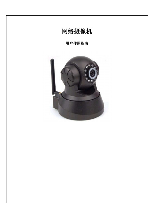
1 第二章 产品产品安装安装.........................................................................................................................................2 第三章第三章 搜索设备搜索设备搜索设备并登陆并登陆.............................................................................................................................3 第四章 视频属性设置和云台控制操作..................................................................................................4 第五章第五章 系统设置选项................................................................................................................................4 第六章第六章 报警设置报警设置.........................................................................................................................................6 第七章第七章 控制面板.........................................................................................................................................7 第八章第八章 注销.................................................................................................................................................8 第九章第九章 通过通过通过广域广域广域网访问网络摄像机网访问网络摄像机 (9)第一章 产品介绍IPCAM 是一种通过网络传输动态视频的设备,它可以将本地的动态视频通过网络传输到世界各地有网络连接的地方,通过互联网,用户可以随时看到想监控的地方,拓展了人类的视野范围。
CAM-3软件使用说明书

气溶胶、碘连续监测仪使用说明书概述:气溶胶、碘连续监测仪是实时监测空气中人工放射性α和β气溶胶以及放射性碘的仪器。
其运行方式及参数可以根据工作场所、工作性质的不同,进行合理的设置。
合理的设置参数,可以更好的满足用户的不同要求。
此说明书在说明本软件的同时,对各参数的意义也做了明确的说明。
一、软件主界面介绍仪器电源开启后启动计算机电源,在计算机界面上,双击“”进入如(图1) 所示的主界面。
(图1)主界面图中从上至下主要由菜单项、能谱显示区、信息显示栏、控制按钮以及仪器当前的状态显示栏组成。
下面具体介绍它们所代表的意义。
启动程序,程序经过“加载参数”等一系列过程后,自动运行到如(图1)所示的主界面图。
注意:在此过程中,如果仪器弹出如(图2)所提示的对话框,则可能是仪器USB接口没接好,需要打开仪器前门,在各自的原位置拔插一下USB口。
(图2)背景为蓝色的能谱显示区,用来显示放射性α气溶胶或者放射性I的能谱。
正常运行仪器时,可以选择用户想显示的能谱(在能谱区下面有“能谱显示”信息栏,如果选中“碘”,则显示当前运行状态下碘的能谱。
如果选择“气溶胶”,则显示当前运行状态下α气溶胶的能谱)。
其中,α气溶胶的能谱共分三个区,三个区的具体区间可以在“系统设置/运行和通讯/其他参数”(图9)中设置。
碘只有一个计数区,具体位置可以在“系统设置/运行和通讯/碘参数设置”中设置。
(注意:一般情况出厂前α气溶胶的三个区间或碘计数区已经设置好,不要轻易改动,否则会直接影响α气溶胶或碘的活度浓度。
)用鼠标单击蓝色区域内任意一点,黄色线便跳到此计数道,左右方向键可以微移此线。
在这条线移动的同时,主界面最下方的状态栏第二项会显示此时黄线所在的能谱的道址和此道址的当前计数两个信息。
信息显示栏主要显示仪器测量结果。
其中“能谱计数区.P”分别显示仪器运行中α气溶胶三个区域的总计数。
“β计数.P”用来显示仪器运行中β气溶胶的总计数。
“能谱计数区.I”用来显示碘计数区总计数。
IPCAM远程设置说明书
远程设置分为三步:a)改IP首先看下自己电脑的IP是多少,观看步骤:在桌面网上邻居上点击右键----选择”属性”----在”本地连接”上点右键----选择”属性”----选择”internet协议(TCP/IP)----点”属性”,这样你就可以看到你电脑的IP了.然后你再看下网络摄像机的IP是多少,先打我们的IP搜索器,然后搜索一下你可以看到,左边的是电脑的IP,右上角是网络摄像机的IP,现在就是要把网络摄像的IP改成跟电脑IP在一个网段内,首先,你要把网络摄像机的子网掩码,网关IP和DNS1改成跟电脑这边显示的一模一样,然后,你再看上面示图,电脑的IP是192.168.1.110,而网络摄像机的IP是192.168.16.139,这两个IP 一个是在1网段,一个是在16网段,你就要把网络摄像机的网络改到跟电脑在同一个网段,也就是把16改成1,然后IP的最后一个数字110和139,如果这两个数字是一样,就要改一下,不能用一样的,而且只能是2-254这个数值之这样你再重新点搜索,选择预览,就可以在IE上面看到图像了。
* 有些电脑是用的自动获取IP地址,这样的话就看不到电脑IP是多少,需要这样操作才行:第一步、点开始菜单—运行—输入cmd,然后确定第二步、在弹出的对话框中输入ipconfig /all,然后回车这样你就可以知道你的IP地址、子网掩码、网关和DNS是多少了b)申请域名域名实际上就是一个网址,就像一样,不过我们这里的域名是借助其它域名网站建立的,因此是个二级网站。
我们在远程看摄像机的监控图像,就是要通过摄像机所在网络的公网IP 来找到它,但是现在所使用的公网IP都是动态的,每过16个小时就会变化一次,这样一来,我们每次远程看时就需要找一下摄像机所在网络的公网IP是多少,这样一来就很麻烦,申请域名就是为了弥补这个缺点,现在有很多域名服务网站,我们随意选择一个在上面申请域名,然后下载它提供的客户端在与摄像机同一局域网内的任意一台电脑上运行就可以,客户端会自动每过一段时间刷新一下摄像机所在网络的公网IP,如果公网IP变了,它就会自动将新的IP与你所申请的域名进行绑定,这样一来,不管你什么时候打开域名,都是打开的你摄像机正在使用的IP。
华硕camfunction软件说明书
CAMFUNCTION DATASHEET(Covers IP, Standard and Pro versions)CAMFUNCTION is a software package that allowscontrol of multifunction dome cameras, telemetryreceivers, IP cameras / IP video servers, videomatrix/switchers and video recording devicesusing a PC. The cameras can be controlled bymouse/touchscreen via the on-screen ‘joystick’, PCkeyboard or by a physical joystick which isconnected to the back of the PC.CAMFUNCTION includes a map layout facility whichdisplays a map of the premises including thelocation of all cameras. Simply select a cameraeither by using the camera select list or click oneof the camera icons displayed on the map. Thismakes it easy for the operator to know exactlywhere the cameras are positioned, even if they arenew to the CCTV system. ‘Hot spot’ icons on themap can also trigger multiple cameras in the areato turn and view specific points on the map (Idealfor following suspects in retail environments).CAMFUNCTION also offers VCR/Digital recordercontrols, allowing integration of the whole CCTVsystem through a single on-screen interface. Thisreduces the desk top space required and allowsthe VCR to be positioned in a secure area.Many of the selection buttons can be titled giving the operator a clear indication of their function. This vastly reduces operator training times, as well as mistakes made by “finger trouble” on the part of operators; a common problem in security system management. You can even have up to sixteen user configurable buttons on the main operators screen to trigger function keys adding a personalisation which previously could only be achieved through expensive bespoke programming. To ensure security of the system each operator has their own password and functions available to them.Function keys can be created to do a number of operations with a single key press. Features such as camera and preset selection, snapshot, VCR commands and tour selection can now be triggered by a keyboard or on-screen button. These function keys can also be triggered by timers at programmable times.Images can be displayed on CCTV monitors or the PC screen when the CCTV Grab video capture card is used. When using the CCTV Grab card CAMFUNCTION has a snapshot feature which enables you to store a particular picture on to the hard disk. The software can be set to grab snapshots at selected intervals. CAMFUNCTION has a built in playback viewerwhich enables pictures to be printed or faxed direct from the PC or saved to floppy disk and emailed.Camfunction has the ability to email a picture to up to 20 email addresses. The email feature can be programmed on to the software’s function keys. These can be triggered by an alarm input, keyboard, timers, map icons or on-screen buttons. The email can have a JPEG imaged attached (of an alarm trigger point for example) or just a text message (ideal for mobile phone users). The web upload command can again be put into a function key and is intended for use by anyone who wants to show pictures from CCTV cameras on the internet or intranet. If users have a permanent connection to the internet available (cable modem or DSL) then pictures will be uploaded at a specified rate or the software can be set to make a dial up connection via phone line, upload the picture and then disconnect to save on call costs.Control over a computer network gives multiple users control of the CCTV system. Control is achieved by connecting the control equipment either to a PC running Camfunction OR to a dedicated Video Server (call for list of compatible Video Servers). Additional PCs requiring network control must be running Camfunction.Camfunction can interface with non CCTV equipment such as alarm panels or Access control equipment using it’s‘generic alarm protocol’ via an RS232 or DDE link connection. It can also accept alarm inputs direct to the PC or via compatible alarm panels.Camfunction VersionsCAMFUNCTION is split into three different versions to be used in different applications:• Camfunction IP- Low cost version for multiple network users, no local port connections only network connections to cameras, video servers and NVRs / DVRs. Does not support Alarm Device functionality. Maximum of 16 IP devices. • Camfunction Standard- Version for controlling up to 32 cameras. Supports Alarm Device functionality. Will also support up to 32 IP devices. Sold with or without capture card.• Camfunction Pro- Version for controlling 33 cameras and above up to 999 cameras. Supports Alarm Device functionality. Will also support up to 999 IP devices. Sold with or without capture card.• All versions can connect to CCTV Software’s digital recording software ‘PC Multiplexer’ range.Hardware / Software RequirementsPC & Display Minimum of Pentium 3 333Mhz or higher with VGA 16bit colours and 1 spare PCI slot.PC Ram 512 MB or abovePC Hard drive Min. 20MB of hard disk space. 80 MB or above if using snapshots.PC CD Rom drive 4x speed or fasterPC Control device Mouse/touchscreen and / or PC analogue joystick (4 buttons).PC Hardware key (dongle) port 1 parallel port or 1 USB port if you order USB version (add –USB to part number for this)PC RS232 Communications ports 1 mouse / touch-screen port, 1 serial port for cameras, 1 serial port for VCR’s, 1 serial port for video switchingdevicePC Operating System & Network Windows 98, 2000, ME, XP or Vista with TCP/IP protocol for network operationCompatible cameras and telemetry receivers (RS485/422 versions)New cameras being added all the time Panasonic CSR/CPR/CLR/BLR ranges BBV RX450/550 RVR’sCBC (Computar) SMD range BBV Telemetry Rvr’s (through TX1000/1500) Sanyo VCC range Sony SSC DC590 rangeStar Micronics MD range Philips/Burle TC700/TC8560 DOMES/RVR’s Pelco Spectra Dome (Pelco D) Dennard domeVCL Microsphere range Synectics Telemetry Rvr’s (through matrix) JVC TK-C675/TK-C553/TK-C676/TK-C1480/TK-1460 Meyertech Telemetry Rvr’s & domesVicon Dome / Rvr’s (Variable speed) CBC (Computar) CS Rvr’s rangeVicon Dome / Rvr’s (Fixed Speed). Panasonic CS/CW rangeGyyr Vortex Dome Mark Mercer Electronics DomesCSLILIN-PIH-Receiver (through PIH-MATRIX) Sensormatic Speed Dome Ultra Range Molynx Telemetry Rvr’s American Dynamics Delta Dome Range Dennard Telemetry RX (Through DTX1000) Forward Vision Domes+ Pan/Tilt heads360 Vision Dome Red Vision Dome range (Pelco D)Further models being added, please contact us for latest information.Compatible video switching devices BBV TX1000 / TX1500 CBC(Computar) CS16.4 Video MatrixCSLIN-PIH-Matrix Extron Matrix 50 (Audio & Video)Mark Mercer Matrix Meyertech Video MatrixPanasonic WJ-HD500 VCL Maxcom & Mini MatrixSynectics Video Matrix Dennard DTX1000 SwitcherVideo Switch VSX416 Molynx Visilynx IIIiMolynx 600 series & Visilynx II Telemetry Controllers Molynx Visilynx II+ (via PCCON2)Dedicated Micros Digital Sprite via (CC01A) Vicon Matrix SystemsPelco CM6700/CM6800/CM9500/CM9760/CM9770 Matrix Panasonic WJ-SX150/550/650 Matrix360 Vision MatrixAny multiplexer or equipment controllable using our other control software (e.g. `plus’ or `studio’ range).PC Multiplexer software with multi-input capture board from CCTV SoftwareCompatible IP video Devices Axis 2420/2100/2110/2120/2130/210/211/221/213/205/206/207 CamerasAxis 2400/2401/2400+/2401+/241S/241Q/243S/243SA/243Q ServersJVC VN-C1U/VN-C2U/VN-C3U/VN-C30U/VN-C925U/VN-C955U CamerasSony SNT-V304 Server Sony SNC-VL10 Camera Sony SNC-RZ30 CameraVivotek 2000/3000/6000/7000 Series devices Gyyr Tango II ServerMobotix M1/M10/D10/V10 Cameras Dallmeier Digital Recorder RangePanasonic WV-NP472 Cameras Panasonic WV-NS320/324/202 CamerasPanasonic WV-NM100 Camera Panasonic BL-C1A/BL-C10/BL-C20/BL-C30 CameraPanasonic WV-NW470/474 Camera Panasonic KX-HCM8/10/230/250/270/280 CamerasPanasonic BB-HCM331/BBHCM381 Panasonic WV-NS950/WV-NW960 CamerasPanasonic WV-NP240/NP244/NP1000 Cameras & I Pro rangePanasonic WJ-HD220/309/316/500 WJ-RT416 Digital Recorder Panasonic WJ-ND300/400 NVRCompatible VCR’s/digital recorders Most RS232 controlled VCR’s, Many popular Digital Video Recorders including:Panasonic WJ-HD220/309/316/500/ Digital Recorder, via RS485, RS232 or IP Ethernet portPanasonic RT416 & ND300/ND400 Via IP Ethernet port, Panasonic WJ-HD88 via RS485 portDedicated Micros Digital Sprite via (CC01A) Sony HSR1&2CCTV Software ‘PC Multiplexer’ product range 360 Vision Avalon DVRFurther models being added all the time, please contact us for latest information.Compatible Alarm input devices Generic Alarm Device (Must comply to CCTV Software’s ‘GENERIC ALARM PROTOCOL’)AC16 Alarm module (16 inputs, RS485 connection to PC)PC Game port (4 inputs)Synectics AL24 alarm unitGalaxy (via IP Ethernet port, SIA protocol) PAC Access ControlGalaxy (via RS232 port, SIA protocol) Panasonic IP Alarm Protocol (DVRs/NVRs/Cameras)Vicon Matrix Alarm unit Moxa IOLogic E2200 Series Ethernet I/O ServerFurther models being added all the time, please contact us for latest information.Compatible video capture card CCTVGRAB card, for use with Windows 98, 2000, ME & XP. PCI slot. VGA card must have direct draw capability.DirectX8.1 or above required.CAMFUNCTION is aU.K. OFFICE CCTV SOFTWARE LTD U.S. OFFICE CCTV SOFTWARE INC37 CHAMBRES RD 11208 WAPLES MILL RDSOUTHPORT SUITE 208MERSEYSIDE FAIRFAXPR8 6JG VA 22030U.K. U.S.A.TEL +44 (0)1704 548675 U.S. EMAIL ********************** FAX +44 (0)1704 548679************************** Ref:CAMFUNC0909product。
LG 360 CAM 说明书
Flash 5500K
Cloudy 6000K
Shade 7400K
Warm light, soft tones WB2400
Compensate for cool lights WB5000
For natural tones WB6000
Get creative with your 360° photos and videos by adjusting the camera settings.
To get started, open the 360 CAM Manager app on your smartphone and tap the Camera icon on the app home screen.
Manual Mode
Fine-tune your 360° captures by adjusting a multitude of different settings.
Exposure
Correct the brightness of photos and videos with one simple adjustment.
ISO 2700 = Too noisy
Slow Shutter Speed 1/2 sec.
Faster Shutter Speed 1/500 sec.
NOTE: When you adjust ISO it is necessary to adjust Shutter Speed (and vice versa) for a good exposure. Typically, the higher ISO, the faster Shutter Speed.
Decrease exposure if image is too bright (-)
CCTV CAM340+快速启动指南说明书
CAM340+ Quick Start GuidePackage ContentsOverview12346578910Setup CAM340+1. Install the CAM340+ on top of TV or on a tripod.OR2. Connect CAM340+ to PC with provided USB cable. If you like to use type-Cconnector on newer PC, connect your adapter to USB cable, and then connect type-C side of adapter to PC.USB 2.0USB 3.0USB 3.0USB type-A to type-C adapter (optional)oror(1080P)3. Please connect CAM340+ to USB3.0 port on PC to get sufficient power. If youconnect CAM340+ to USB2.0 port on PC, please connect provided power adapter to CAM340+ and wall when a warning (As figure shown) is displayed on PC. [Note] The warning message display time is short.1. Lens(Max. viewing angle 120°) 2. IR receiver 3. Status light 4. Microphone 5. Kensington slot 6. Mount clip 7. Tripod screw hole 8. RESET pin9. USB type-C connector 10. DC power jack4. Select CAM340+ as the camera or video device in your app. If you want to useCAM340+ microphone, please select CAM340+ as your microphone or audio device. For multi-person conferences, it is recommended to use an external professional microphone or to use with the AVer professional speaker microphone device for the best conference results. You can use PTZApp to disable microphone function.TV5. For advanced setting and firmware update, please download AVer PTZApp from/download-centerStatus LEDLEDStatusAmber Not in useSolid Green Camera is operated now Blinking greenFirmware updating[Note]CAM340+ is a Plug-n-Play Conference Camera. The system requires no special drivers. Please visit below URL for more information.Global: US: Install AVer PTZAppPlease go to /download-center to download the AVer PTZApp. After downloading, double-click on the file and follow the on-screen instructions to complete the installation.After installing the AVer PTZApp, double-click on the AVer PTZApp icon to run the application.Use AVer PTZApp1. To run your video application, a plug-in request will be displayed on your videoapplication interface. Click on it to accept the plug-in; your video application can now be control by AVer PTZApp and remote control.2. During your video call, you can use the AVer PTZApp to pan, tilt and zoom thecamera in/out and enable/disable the backlight feature, set up camera brightness and sharpness. For more details, please refer to the user manual.3. FOV(Field of View): User can select the camera view range – Wide room_120° orDepth room_90°.4. Flip: If the CAM340+is installed in the upside down position, please enable the "Flip ”function in the AVer PTZApp, and the screen will display normally.5. For USB Data Transfer Mode, pleaseselect mode in Mac OS and Windows as: ✓ For Mac OS: isochronous mode ✓ For Windows: Bulk modeHotkey ControlEnable hotkey control to use keyboard control camera’s movement and backlight function. 1. Select “Settings ”2. Set Hotkey Control to “On ”.3.A hotkey description as below figure shown:Install EZLivePlease go to /download-center to download the AVer EZLive software. After downloading, double-click on the file and follow the on-screen instructions to complete the installation.Use AVer EZLiveDuring a video call, EZLive can help user to do:(4)(5)(1)(1) Camera ePTZ(2) Volume control for the speaker connected(3) Capture camera’s still images (4) Record video(5) Live stream to Youtube, Livehouse.in, USTREAM…etc. (6) Camera Zoom in/out (7) Capture PC screen shot (8) Record PC screen video (9) Set up livestream(10) Open file management to retrieve photos and video files (11) Livestream setting(12) Drawing tool1Remote ControlThe remote control is an optional accessory. For purchasing, please contact your dealer.*Function requires AVer PTZApp**Not supported for CAM340+⏹AAA Batteries are required.⏹Camera select: If you only have one camera that requires no additional setting, thedefault is camera 1.⏹If you press camera 2 or 3 on the remote control, you will find your remote can’t controlyour camera. In this case, please press camera 1 on your remoter again.⏹for 1 second to switch lens FOV between Wideroom 120° or Depth room 90°More HelpFor FAQs, technical support, software and user manual download, please visit:Global: /technical-supportUS: https:///business/support/Contact InformationGlobal:AVer Information Inc.8F, No.157, Da-An Rd., Tucheng Dist.,New Taipei CityTaiwanTel: +886-2-2269-8535Europe B.V.:AVer Information Inc.Westblaak 140, 3012KM, Rotterdam, NetherlandTel: +31(0)10 7600 550Technical support: ***************F ederal Communication Commission Interference StatementThis device complies with Part 15 of the FCC Rules. Operation is subject to the following two conditions:(1) This device may not cause harmful interference, and (2) this device must accept any interferencereceived, including interference that may cause undesired operation.This equipment has been tested and found to comply with the limits for a Class B digital device, pursuantto Part 15 of the FCC Rules. These limits are designed to provide reasonable protection against harmfulinterference in a residential installation. This equipment generates uses and can radiate radio frequencyenergy and, if not installed and used in accordance with the instructions, may cause harmful interferenceto radio communications. However, there is no guarantee that interference will not occur in a particularinstallation. If this equipment does cause harmful interference to radio or television reception, which canbe determined by turning the equipment off and on, the user is encouraged to try to correct theinterference by one of the following measures:- Reorient or relocate the receiving antenna.- Increase the separation between the equipment and receiver.- Connect the equipment into an outlet on a circuit different from that to which the receiver is connected.- Consult the dealer or an experienced radio/TV technician for help.FCC Caution: Any changes or modifications not expressly approved by the party responsible forcompliance could void the user's authority to operate this equipment.CAUTIONRisk of explosion if battery is replaced by an incorrect type.Dispose of used batteries in a safe and proper manner.©2020 AVer Information Inc. All rights reserved.US:AVer Information Inc.668 Mission CtFremont, CA 94539, USAToll-free: 1(877)528-7824Local: 1(408)263-3828。
- 1、下载文档前请自行甄别文档内容的完整性,平台不提供额外的编辑、内容补充、找答案等附加服务。
- 2、"仅部分预览"的文档,不可在线预览部分如存在完整性等问题,可反馈申请退款(可完整预览的文档不适用该条件!)。
- 3、如文档侵犯您的权益,请联系客服反馈,我们会尽快为您处理(人工客服工作时间:9:00-18:30)。
专业综合实践说明书学院名称:机械工程学院专业:机械设计制造及其自动化班级: 1 姓名:学号: 12321107 指导教师:施晓芳2016 年 2 月目录第1章太阳花造型训练 (1)1.1 造型软件AutoCAM简介 (1)1.2零件造型过程 (2)第2章太阳花数控加工仿真训练 (5)2.1 MasterCAM软件特点简介 (5)2.2 加工工艺方案确定 (5)2.3 加工造型、加工参数设计及其加工刀具选择 (6)2.3.1 工序1 (6)2.3.2 工序2 (9)2.4 太阳花图标加工轨迹仿真 (100)第3章太阳花图标的数控加工 (13)3.1 加工程序生成 (13)3.2 手工对刀 (16)3.3 程序传输及加工图形 (17)参考文献 (18)第1章太阳花造型训练1.1 MasterCAM软件简介MasterCAM软件已被广泛的应用于通用机械、航空、船舶、军工等行业的设计与NC加工,从80年代末起,我国就引进了这一款著名的CAD/CAM软件,为我国的制造业迅速崛起作出了巨大贡献。
MasterCAM具有强劲的曲面粗加工及灵活的曲面精加工功能。
MasterCAM提供了多种先进的粗加工技术,以提高零件加工的效率和质量。
MasterCAM还具有丰富的曲面精加工功能,可以从中选择最好的方法,加工最复杂的零件。
MasterCAM的多轴加工功能,为零件的加工提供了更多的灵活性。
MasterCAM不但具有强大稳定的造型功能,可设计出复杂的曲线、曲面零件,而且具有强大的曲面粗加工及灵活的曲面精加工功能。
其可靠刀具路径效验功能使MasterCAM可模拟零件加工的整个过程,模拟中不但能显示刀具和夹具,还能检查出刀具和夹具与被加工零件的干涉、碰撞情况,真实反映加工过程中的实际情况,不愧为一优秀的CAD/CAM软件。
同时MasterCAM对系统运行环境要求较低,使用户无论是在造型设计、CNC铣床、CNC车床或CNC线切割等加工操作中,都能获得最佳效果。
MasterCAM提供400种以上的后置处理文件以适用于各种类型的数控系统,比如常用的FANUC系统,根据机床的实际结构,编制专门的后置处理文件,编译NCI文件经后置处理后便可生成加工程序。
MasterCAM X2是与微软公司的Windows 技术紧密结合,用户界面更为友好,设计更加高效的版本。
借助于MasterCAM软件,用户可以方便快捷地完成从产品2D/3D外形设计、CNC编程到自动生成NC代码的整个工作流程,因此被广泛应用于模具制造、模型手板、机械加工、电子、汽车和航空等行业。
MasterCAM基于PC平台,易学易用,具有较高性价比,是广大中小企业的理想选择,也是CNC编程初学者在入门时的首选软件。
MasterCAM包括CAD和CAM两个部分,Master cam的CAD部分可以构建2D平面图形、构建曲线、3D曲面和3D实体。
CAM包括5大模块:Mill、Lathe、Art、Wire和Router。
1.2零件造型过程打开MasterCAM点击solids进行绘制,选择实体制图,点击primitives,画边长为100mm高度为50mm的正方形,再选择Base point输入(0,0,-50)作为原点,如图1-1所示。
图1-1 绘制矩形点击create中的Arc,用circ pt+rad画圆,用样条曲线命令spline画出太阳花的外轮廓,并使用打断中的At inters打断所有节点进行修剪,如图1-2所示。
图1-2 绘制圆选择xforms把图层向上评议10个单位长度再用solids中的Extruate拉伸成一个深度为13实体,如图1-3所示。
图1-3 拉伸实体利用命令solids=>Boolean=>remove把实体去除掉如图1-4所示。
图1-4 三维造型Crate=>letters写入学号0709,并使用与前面步骤相同指令做出深度为0.5的实体,如图1-5所示。
图1-5 三维造型绘制零件图:采用零次局部剖识图,反映出零件加工铣槽部分的深度。
用AutoCAD绘制出零件图,并标注总体尺寸,定位尺寸。
最终加工完成的零件图如下图所示。
图1-6零件图第2章太阳花数控加工仿真训练2.1 MasterCAM软件特点简介MasterCAM X2具有全新的Windows操作界面,在刀路和传输方面更趋完善和强大,其功能特点如下:(1)操作方面,采用了目前流行的“窗口式操作”和“以对象为中心”的操作方式,使操作效率大幅度提高;(2)设计方面,单体模式可以选择“曲面边界”选项,可动态选取串连起始点,增加了工作坐标系统WCS,而在实体管理器中,可以将曲面转化成开放的薄片或封闭实体等;(3)加工方面,在刀具路径重新计算中,除了更改刀具直径和刀角半径需要重新计算外,其他参数并不需要更改。
在打开文件时可选择是否载入NCI资料,可以大大缩短读取大文件的时间;(4)MasterCAM系统设有刀具库及材料库,能根据被加工工件材料及刀具规格尺寸自动确定进给率、转速等加工参数;(5)MasterCAM是一套以图形驱动的软件,应用广泛,操作方便,而且它能同时提供适合目前国际上通用的各种数控系统的后置处理程序文件。
以便将刀具路径文件(NCI)转换成相应的CNC控制器上所使用的数控加工程序(NC代码)。
2.2加工工艺方案确定数控加工工艺方案设计的主要内容:1)零件加工工艺性分析:对零件的设计图和技术要求进行综合分析。
2)加工方法的选择:选择零件具体的加工方法和切削方式。
3)机床的选择:选择合适的机床既能满足零件加工的外廓尺寸,又能满足零件的加工精度。
4)工装的选择:数控设备尽管减少了对于夹具的依赖程度,但还不能完全取消,在满足零件加工精度和技术要求的前提下,工装越简单越好。
线,进行加工余量分配。
6)刀具的选择:根据加工零件的特点和精度要求,选择合适的刀具以满足零件加工的要求。
7)切削参数的确定:确定合理的切削用量。
8) 数控编程方法的选择:根据零件的难易程度,采用手工或自动编程的方式,按照确定的加工规划内容进行数控加工程序编制。
设置时应根据我们预先拟定的加工工艺参数输入相应的值。
合理选择切削用量的原则是:粗加工时,一般以提高生产率为主,但也应考虑经济性和加工成本;半精加工和精加工时,应在保证加工质量的前提下,兼顾切削效率、经济性和加工成本。
具体数值应根据机床说明书、切削用量手册,并结合经验而定。
根据实际情况,拟定下面数控加工参数:工序1 铣工件外形,深度为3mm。
工序2 雕刻学号,深度为1mm。
2.3加工造型、加工参数设计及其加工刀具选择数控加工工艺方案设计的主要内容包括确定加工方法,确定零件的定位和装夹方案,安排加工顺序,以及安排热处理、检验及其辅助工序等。
设计者应从生产实践中总结出来一些综合性的工艺原则,结合实际的生产条件提出几个方案,进行分析对比,选择经济合理的最佳方案。
合理的工艺方案能保证零件的加工精度、表面质量的要求。
数控加工工艺方案设计的主要内容:1)零件加工工艺性分析:对零件的设计图和技术要求进行综合分析。
2)加工方法的选择:选择零件具体的加工方法和切削方式。
3)机床的选择:选择合适的机床既能满足零件加工的外廓尺寸,又能满足零件的加工精度。
4)工装的选择:数控设备尽管减少了对于夹具的依赖程度,但还不能完全取消,在满足零件加工精度和技术要求的前提下,工装越简单越好。
线,进行加工余量分配。
6)刀具的选择:根据加工零件的特点和精度要求,选择合适的刀具以满足零件加工的要求。
7)切削参数的确定:确定合理的切削用量。
8 )数控编程方法的选择:根据零件的难易程度,采用手工或自动编程的方式,按照确定的加工规划内容进行数控加工程序编制。
数控加工工艺设计的内容非常具体、详细。
在确定工艺方案时,要考虑的因素较多,如零件的结构特点、表面形状、精度等级和技术要求、表面粗糙度要求等,毛料的状态,切削用量以及所需的工艺装备,刀具等。
以下是设计工艺方案必须考虑的几个重要环节:加工方法的选择、工艺基准的选择、确定加工步骤、工艺保证措施。
根据所要加工的零件,结合学校数控铣实际情况,我们选择直径为8mm 的高速钢立铣刀,直径为1mm ,刀尖为0.3mm 的高速钢麻花钻。
2.3.1 工序1铣工件外形,深度为3mm ,一次进刀,背吃刀量3mm 。
确定工序一进给速度和主轴转速:1)确定背吃刀量:a p =3mm 2)确定进给量:依据采用的考文献[1]表5-14,选用的高速钢立铣刀,再依据参考文献[1]表5-14,取该工步的每齿进给量f z =0.02mm/z则每转进给量f=0.02⨯4=0.08mm/r 。
3)计算切削速度:查参考文献[4]表5-14,取v=30m/min ,d v n π1000= (2-1) 由公式(2-1),min /66.119383010001000r d v n =⨯⨯==ππ,其中d=8mm, 查参考文献[1]表4-16,立式铣床的钻速表,n=1195r/min,公式(2-1)变形得: 1000dnv π= (2-2)由(2-2)式,调整切削速度:min /03.301000119581000m dn v =⨯⨯==ππ取n=1200r/min 。
外形铣选择直径为8mm 高速钢铣刀,刀具号为1,工件材料为铝件,切削深度为3mm ,转速1200r/min 。
T oolpaths=>Operations=>Parameters=>Tool parameters ,做参数调整,如下图所示。
图2-1 工序一刀具选择图2-2 工序一切削深度2.3.2 工序2雕刻学号,深度为0.3mm,选择直径为0.5mm的高速钢麻花钻,刀具号为2,切削深度为0.3mm,转速1500r/min,工件高为50mm。
确定工序三进给速度和主轴转速:=0.3mm1)确定背吃刀量:ap2)确定进给量:选用的是高速钢麻花钻,依据参考文献[4]表5-14,取该工步的每齿进给量f=0.18mm/zz则每转进给量f=0.18⨯4=0.72mm/r3)计算切削速度:查参考文献[4]表5-23,取v=4m/min,由(2-1)min1500rn=,其中d=1mm,/查参考文献[4]表4-16,立式铣床的速度表,n=1500r/min,调整切削速度,由(2-2):minv=.3m/93取v=4m/min。
图2-3工序二刀具选择图2-4工序二切削深度2.4 太阳花图标加工轨迹仿真在Mastercam中定义工件尺寸,Toolpaths=>Jobsetup ,直接在“Job setup”对话框的X、Y、Z输入框中输入工件的长103,宽103,高50,如下图所示。