电磁飞机弹射系统的设计与仿真(英文版)
航母电磁弹射原理

航母电磁弹射原理航母电磁弹射(Electromagnetic Aircraft Launch System,简称EMALS)是一种利用电磁力将飞机从航母上快速起飞的技术。
相比传统的蒸汽弹射系统,EMALS具有更高的效率、更低的维护成本和更广泛的适用性。
下面将从原理、优势和应用等方面介绍航母电磁弹射。
一、原理航母电磁弹射系统主要由电磁发射器、电源系统和控制系统三部分组成。
电磁发射器采用线圈和电容器构成,通过电源系统提供高电流短时间放电,使电磁发射器产生强大的磁场。
当飞机停在起飞甲板上时,电磁发射器会产生一个瞬时的电磁力,将飞机加速到起飞速度并抬升到安全高度。
控制系统负责控制电磁发射器的工作时间和电流强度,以适应不同机型和载重情况。
二、优势航母电磁弹射相比传统的蒸汽弹射系统具有诸多优势。
首先,它具有更高的效率。
蒸汽弹射系统需要使用大量的蒸汽来产生动力,而EMALS则是通过电能转化为动能,能更有效地利用能源。
其次,EMALS的启动速度和加速度可根据飞机的不同需求进行调整,提供更加精确的起飞参数,减少了对飞机的损伤。
再次,EMALS的维护成本更低。
相比蒸汽弹射系统,EMALS的零部件更少,维护更加简单,大大降低了航母运营的成本。
三、应用航母电磁弹射系统已经在美国海军的福特级航空母舰上得到应用,并取得了良好的效果。
相比传统航母上的蒸汽弹射系统,EMALS为飞行员提供了更加平稳和精确的起飞体验,大大提高了飞机的起飞成功率。
此外,EMALS还具有适应不同飞机类型的灵活性,可以支持多种机型的起降,进一步增强了航母的作战能力。
航母电磁弹射系统是一项技术创新,它利用电磁力将飞机从航母上快速起飞。
相比传统的蒸汽弹射系统,EMALS具有更高的效率、更低的维护成本和更广泛的适用性。
随着技术的不断发展,航母电磁弹射系统将会在未来的航母建造中得到更广泛的应用,并为航母作战提供更强大的支持。
电磁飞机弹射系统永磁涡流制动装置的分析与设计
.
… …
磊 { ≥… … … … … … … … … … … … … … … … … … … … … … 一 . 二… … … … . . 一 。 . : … - - -: : … : ….
触持电棚 2 0 1 3 年 第 4 1 卷 第 8 期
电磁 飞 机 弹 射 系统 永磁 涡 流 制 动 装 置 的分 析 与 设 计
Ab s t r a c t : A p e r ma n e n t - ma g n e t e d d y c u r r e n t b r a k e s y s t e m w a s d e s i g n e d f o r t h e EMA L S .T h e t h e o r e t i c a l c a l c u l a t i o n e x p r e s s i o n o f b r a k i n g f o r c e w a s d e r i v e d a n d v a l i d a t e d b y t h e i f n i t e e l e me n t me t h o d .Be s i d e s ,t h e p e ma r n e n t — ma g n e t a ra y wa s o p t i mi z e d i n t h e b a s i s o f t h e o r e t i c a l c a l c u l a t i o n e x p r e s s i o n a n d t h e i f n i t e e l e me n t r e s u l t s ,w h i c h c a n p r o v i d e r e f e r e n c e or f t h e d e s i g n i n g o f p e r ma n e n t - ma g n e t e d d y c u re n t b r a k i n g s y s t e m.
美国新型CVN-21超级航母的设计继续进行
刘振浩 ,等 : 星预警探测仿真模型研究 卫
第 3 卷 2
星载传感器探测信 噪比检测模型的 目标 S R N 仿真
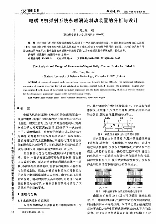
结果如图 l 所示 。 0 结果合 导弹 目标判别 条件 , 目标被判 别为导弹 目标 。仿真结果 同时显示 ,助推段导弹尾焰 的红外辐射信号较 强 ,导 弹 目标的信噪 比最 大 ,随着 导弹飞行 时间增加 ,尾焰红外信号减弱 ,目标信噪 比
图 1 卫星预警探测 系统仿真模型 运行 结 1
美 国新型 C N 2 超 级航母 的设计继续进行 V 一 1
相比其它 家航母 的吨位 ,美国“ 尼米兹” 级和 C N.1 母的吨位 可达 9 0 0 以上 。因此 ,这两种航母被 V 2航 00 吨 非官方称 为“ 超级航母 ” 。这 些航母 中的任一艘 ,其 空中力量就 比其他许 多国家所有航母 空 中力量强。
trso ud r e k cmpe bcgo n s ] . heh l n e sasy o l d x akru d[ .J J
If e l Wae 杨磊,杨杰, nr d i r a Mim. vs( 郑忠龙.海空复杂 背 景 中基 于 自适 应局 部 能量阈 值的红外 小 目标检测 . 红外与毫米波学报 ), 0 62() 1 5 2 0 ,5 14 - . : 4
[ 胡 小云 . 5 】 可见 光侦 察装 备侦 察功 能仿 真模 型研究 [. J 】
指挥控制与仿真, 0 , () 2 72 2. 0 9
4 )预警卫 星探测系统仿真模型运行结果及分析 模型仿真运行结果如 图 1 所示 , 1 结果显示 , 预警 卫星 F可 以探测到导弹 目标 3 7 3 0 6 ,目标识 别模 型判
[] 8 D D J 0 : p r e t f Dees Di inr o o . P -2Deat n o fne c o ay f 1 m t
电磁飞机弹射系统

电磁飞机弹射系统-关键技术电磁弹射器的心脏就是100多米长的直线感应电动机,它推动与飞机相连接的电枢。
而目前电枢基本上是一个U形铝块,装在定子的3个侧面。
直线电机的原理并不复杂.设想把一台旋转运动的感应电动机沿着半径的方向剖开,并且展平,这就成了一台直线感应电动机。
在直线电机中,相当于旋转电机定子的,叫初级;相当于旋转电机转子的,叫次级。
初级中通以交流,次级就在电磁力的作用下沿着初级做直线运动.这时初级要做得很长,延伸到运动所需要达到的位置,而次级则不需要那么长。
实际上,直线电机既可以把初级做得很长,也可以把次级做得很长;既可以初级固定、次级移动,也可以次级固定、初级移动。
然而,电磁弹射器也决不是仅靠直线电机工作的,它总共有强迫储能装置、大功率电力控制设备、中央微机工控控制及直线感应电机。
强迫储能装置强迫储能装置是电磁弹射器的一个瓶颈,在国防方面一直是高度机密的。
作用就是能平时储能,然后把大功率能量在短时间内释放出来。
电磁弹射器工作时间不长,但是在做功时段是个加速度做功的过程,因此不能把它当成恒功率设备来考虑。
电磁弹射系统的强迫储能系统要求在45秒内充满所需要的能量。
最大的舰载机起飞一般需要消耗的能量不会超过120兆焦,而这强迫储能系统最大能储存140兆焦的能量,此时充电功率为3.1兆瓦,算上损失,4兆瓦左右(实际上达不到的),四部电磁弹射系统同时充电,充电总功率可达16兆瓦(1兆瓦=1000KW),可见没有强大的电源是无法满足电磁弹射需求的。
当然,航母上耗电的又岂止是四部电磁弹射器,另外还有电磁轨道炮、升降机、激光(目前激光的功率都不算大)等其它用电加起来的话必须要航母总功率达60兆瓦以上,否则电磁弹射器充电时也会影响其它系统用电的。
电磁弹射器难就难在电能不象蒸汽,根本不适合大容量储存,象储存弹射舰载机这样的能量更是难上加难。
通用原子公司在实验电磁弹射器时对强迫储能装置只字不提,可见其技术的高度机密性非同一般,想突破也非易事。
电磁弹射航母起飞原理

电磁弹射航母起飞原理随着科技不断的进步,航母的技术也在不断升级与发展。
其中,电磁弹射航母作为新一代的航母,被认为是最具发展潜力的航母之一。
那么,电磁弹射航母的起飞原理是什么呢?电磁弹射航母起飞原理简介电磁弹射是一种基于电磁场的高速加速原理,是在航母上使用电磁力将飞机从航母上加速起飞。
电磁弹射航母使用的主要器材是电磁发射器,电磁电机和电源控制系统。
该系统主要由发射器和电磁能量存储器两个部分组成,同时还包括控制系统和能量回收系统。
电磁弹射航母起飞原理运用的是长导轨电磁加速器。
散热泵和电机配有冷却系统和管道以维持工作温度和稳定输出功率。
电容器组成电源,以满足起飞时的短周期负载。
起飞之前,信号将被发送给电磁发射器。
接收到信号后,电磁发射器会在飞机起飞所需要的时间内供应特定的电磁脉冲量。
在发射过程中,将能量传递给储能器并贮藏。
为了平衡电机的运动,磁体在电磁发射器内开始时被反向激活。
当飞机准备起飞时,从储能器中释放出的能量经过导轨传递给电磁绕组。
电磁场会使电流在导轨上形成不断变化的磁场,从而产生向前的推力。
在飞机准备起飞的过程中,除了利用电磁场将飞机加速起飞外,电磁弹射航母还通过一系列的设备对飞机的状态进行监测,以避免发生起飞事故。
航母会通过导轨的起始位置和飞机当前位置之间的距离计算出飞机的速度。
当飞机加速到预定速度时,发射器将自动关机。
以美国福特级核动力电磁弹射航母为例,该航母采用了弹射机制,其起飞原理是由弹射起飞辅助驾驶员来掌控。
他们会调整电磁弹射航母上的弹射器,从而使其在发射飞机时运行更加有效。
系统可以轻松地掌控飞机的起飞速度和瞬间加速度,从而为整个系统提供更好的稳定性和精度。
总结电磁弹射航母起飞原理是一种基于电磁场的高速加速原理,采用电磁力将飞机从航母上加速起飞。
其主要器材是电磁发射器,电磁电机和电源控制系统。
系统可以轻松地掌控飞机的起飞速度和瞬间加速度,从而为整个系统提供更好的稳定性和精度。
随着技术的不断升级和发展,相信电磁弹射航母的应用会越来越广泛,未来的发展潜力无限。
国外飞机电磁轨道发射系统(EMALS)原理简介

国外飞机电磁轨道发射系统(EMALS)原理简介引言随着国产003型航空母舰的成功下水,官方报道新航母将使用电磁弹射系统,由于比预期的蒸汽弹射系统更为先进,一经公布便引发了大家的广泛热议,针对飞机电磁轨道发射系统,我们也学习和整理了国外飞机电磁轨道发射系统(EMALS)的相关资料进行分享。
1概述七十多年来,蒸汽动力弹射器一直是航空母舰发射飞机的标准装置,并配有相关的拉索张紧制动器,用于在着陆时阻拦飞机。
没有它,飞机无法在短短几秒和一百英尺内达到超过 100 节的起飞速度,也无法在类似的时间和距离内从着陆速度减速到完全停止。
这是一个确实有效的系统。
但现在,用于从航母上发射飞机的蒸汽动力弹射器正在被强大的基于电磁的闭环直线电机系统——飞机电磁轨道发射系统 (EMALS) 所取代。
EMALS系统已经安装在航空母舰 Gerald R. Ford (CVN 78) 上。
图1 杰拉尔德·R·福特号(CVN 78)航母是第一个使用 EMALS 设计的航母2EMALS系统原理2.1EMALS基本原理EMALS系统采用直线电机原理,类似于“电磁炮”,在飞机发射轨道上铺设足够多的电磁绕组线圈,当线圈通电后,产生电磁斥力,将金属滑块推出并加速,滑块带动飞机达到起飞所需要的最低速度,从而实现飞机在航母上的起飞。
美国福特航母首先采用了EMALS系统,EMALS系统采用中压交流驱动技术,启动瞬间电流较大,又由于是交流电,一般的储能设备存储的都是直流,无法直接储存交流电,因此设计了飞轮储能设备,可将交流电存储在高速旋转的电机里,弹射飞机时释放交流电能,同时飞轮的转速也下降了,再次弹射前进行充电,飞轮继续保持高速旋转,准备下一次弹射。
图2 EMALS系统示意图2.2组成EMALS系统由六大功能模块组成。
1)主电源接口,它是与船舶配电系统(由核反应堆供电)的互连,并提供动力以驱动储能转子;2)发射电机;3)电力转换设备,为发射电机的一系列绕组供电;4)发射控制,用于管理输送到发射电机绕组的电流,以实现平稳、量身定制的加速,并在条件变化时提供闭环反馈以确保精度;5)储能电动发电机;6)能量分配系统,将能量从电力转换系统传输到发射电机所需的电缆、开关和各个终端。
电磁仿真CST入门教程达索系统百世慧2024新版
宽频带问题
对于需要在宽频带范围内分 析电磁特性的问题,如超宽 带天线、宽带滤波器等,时 域求解器具有优势。
单一频率问题
对于只需要在单一频率点进 行分析的问题,如某些天线 设计、微波器件设计等,频 域求解器更为合适。
计算资源考虑
在选择求解器时还需考虑计 算资源的限制。对于计算资 源紧张的情况,可以选择计 算效率较高的求解器类型。
解压安装包并运行安装程 序。
下载CST软件安装包。
安装步骤
01
03 02
CST软件安装及配置要求
按照安装向导提示完成安装过程。 配置要求 操作系统:支持Windows和Linux操作系统。
CST软件安装及配置要求
硬件要求
建议使用高性能计算机,配备多核处 理器和大容量内存。
软件依赖
需要安装Java运行环境和其他相关依 赖库。
边界条件设置与调整方法
边界条件类型
CST提供了多种边界条件类型, 如完美电导体(PEC)、完美磁 导体(PMC)、阻抗边界等。用 户可以根据仿真需求选择合适的 边界条件类型。
边界条件设置
用户可以在模型的边界上设置边 界条件,以模拟电磁波在无限大 空间中的传播特性。通过设置边 界条件,可以减少仿真计算量, 提高仿真效率。
数值计算方法简介
有限差分法
将连续问题离散化,用差分方程近似代替偏微分方程进行求解,适用于规则网格划分。
有限元法
将连续体离散成有限个单元,对每个单元进行分析并建立方程,最终组装成整体方程进 行求解,适用于复杂形状和不规则网格划分。
时域有限差分法
在时域内对麦克斯韦方程组进行差分离散,通过时间步进方式求解电磁场问题,适用于 宽频带、非线性等问题分析。
边界条件调整方法
基于AMESIM的无人机起飞弹射液压系统的建模与仿真
基于AMESIM的无人机起飞弹射液压系统的建模与仿真秦贞超;周志鸿
【期刊名称】《液压气动与密封》
【年(卷),期】2010(030)009
【摘要】无人机起飞弹射液压系统要求高压、高速、反应时间快,国内进行的相关研究比较少.本文分析了无人机起飞弹射液压系统的工作原理,对插装阀的结构进行了描述,运用AMESIM软件对液压系统进行建模与仿真.仿真结果表明该系统性能良好,能够在短时间内将无人机加速到规定的速度值,同时,该仿真结果也为液压系统的调试提供了参考依据.
【总页数】3页(P16-18)
【作者】秦贞超;周志鸿
【作者单位】北京科技大学机械工程学院,北京,100083;北京科技大学机械工程学院,北京,100083
【正文语种】中文
【中图分类】TH137.7
【相关文献】
1.无人机气液压弹射系统建模与弹射过程仿真分析 [J], 权凌霄;刘建伟;宋豫;赵泽;张伟
2.无人机起飞弹射液压系统的设计与研究 [J], 秦贞超;周志鸿;梁上愚
3.基于AMESim的甘蔗收割机剥叶液压系统的建模与仿真 [J], 雷迪迪;赵铁栓;杨凯;侯跃峰;周闯
4.基于AMESim的侧面叉车液压系统建模与仿真 [J], 徐雄杰
5.基于AMEsim的液压系统建模与仿真 [J], 恭飞; 王雪婷; 杜奕
因版权原因,仅展示原文概要,查看原文内容请购买。
航母舰载机起降方式特点分析及全球现役航母简介-广东造船-120期
假如他没有挂上拦阻索的话他可以在最短的时间之内 加速离开甲板,重新回到降落航线。拦阻索是由液压 制动的,它可以在两秒钟和60 ~ 90 m距离内使飞机停 下来。飞行员会依照甲板上的地勤人员的指示将发动 机的推力降低到慢车并且离开降落区。在异常情况 下,比如舰载机的尾钩损坏了,舰载机无法使用拦阻 索停下来,在甲板上可以拉起拦阻网来协助舰载机迫 降。又或者舰载机会再次拉起,重新降落。
滑跃起飞是是指舰载机先依靠自身动力首先在航 母水平甲板上滑跑,后经航母舰首斜曲面甲板(又称 滑跳式甲板和滑橇式甲板),使舰载机在离舰瞬间被 赋予一定航迹倾斜角和向上的垂直分速度,使舰载机 跃入空中,实现离舰起飞。由于该项技术把甲板尽头做 成斜坡上翘,舰载机起飞后沿着上翘的斜坡冲出甲板, 形成斜抛运动,从而大大缩短了飞机的起飞滑跑距离。 这种起飞方式不需要复杂的弹射装置,但是飞机起飞时 的重量以及起飞的效率远不如蒸汽弹射技术。
作者简介:吴家鸣(1957-),男,教授,博士 收稿日期:20பைடு நூலகம்1-08-15
45
设计开发
Design & Development
拖带的速度,四项速度合成,使舰载机只需滑行几十 米即可获得足够的升力而起飞升空。
蒸汽弹射有两种弹射方式:前轮牵引式弹射和拖 索式弹射。使用前轮牵引式弹射时,舰载机的前轮支 架装上拖曳杆,前轮就直接挂在了滑块上,弹射时由 滑块直接拉着飞机前轮加速起飞。拖索式弹射时,甲 板人员先用钢质拖索把飞机挂在滑块上,再用一根索 引释放杆把其尾部与弹射器后端固定住。弹射时,猛 力前冲的滑块拉断索引释放杆上的定力拉断栓,牵着 飞机沿轨道迅速加速,在轨道末端把飞机加速到直起 飞速度抛离甲板,拖索从飞机上脱落,滑块返回弹射 器起点准备下一次工作。
航母中电磁弹射原理的应用
航母中电磁弹射原理的应用1. 引言航母是现代海军力量中最重要、最复杂的舰种之一。
它们具有强大的打击力量和远程作战能力,能够快速部署和执行各种任务。
而其中一个关键的技术就是电磁弹射系统。
本文将探讨电磁弹射原理以及它在航母中的应用。
2. 电磁弹射系统的原理电磁弹射系统是一种将舰载飞机从航母上快速、安全地起飞的技术。
它使用电磁力代替传统的蒸汽弹射系统,能够更加精准地控制飞机的加速度和速度。
电磁弹射系统由两部分组成:线圈和飞机的起飞车辆。
线圈是通过电流产生的磁场来产生推力,从而推动起飞车辆和飞机。
起飞车辆与飞机的前轮连接,通过电磁力将飞机加速到起飞速度。
当飞机达到所需的速度后,起飞车辆会脱离飞机,飞机则继续升空。
3. 电磁弹射系统的优势与传统蒸汽弹射系统相比,电磁弹射系统具有多种优势。
3.1 更加精确的控制通过电磁力产生的推力可以更加精准地控制飞机的加速度和速度,从而使起飞更加平滑和可控。
这对于起飞重量较大的飞机来说尤为重要,可以减少起飞过程中的冲击力,降低对飞机和航母的损伤。
3.2 更加高效的能量转换电磁弹射系统利用电流产生的磁场来产生推力,相比于蒸汽弹射系统,能量转换更加高效。
电磁弹射系统可以在短时间内提供更大的推力,使得起飞过程更加迅速,从而增加了航母的作战效率。
3.3 更加适应不同飞机电磁弹射系统可以根据不同飞机的起飞需求进行调整,因此可以适应不同起飞重量和速度的飞机。
这使得航母在执行不同任务时具有更大的灵活性和多样性。
4. 航母中电磁弹射原理的应用航母中的电磁弹射系统有广泛的应用。
以下列举了一些主要的应用:4.1 起飞和着舰操作航母是一个相对狭小的空间,飞机需要在有限的跑道上起飞和着舰。
电磁弹射系统可以在较短的距离内将飞机加速到起飞速度,从而减少了起飞距离,使得船台上能够容纳更多的飞机。
另外,电磁弹射系统也可以用于着舰过程中的减速,使得飞机能够更快地停靠在船台上。
4.2 空中巡逻和战斗行动航母的主要任务之一是空中巡逻和战斗行动。
- 1、下载文档前请自行甄别文档内容的完整性,平台不提供额外的编辑、内容补充、找答案等附加服务。
- 2、"仅部分预览"的文档,不可在线预览部分如存在完整性等问题,可反馈申请退款(可完整预览的文档不适用该条件!)。
- 3、如文档侵犯您的权益,请联系客服反馈,我们会尽快为您处理(人工客服工作时间:9:00-18:30)。
Design and Simulation of an Electromagnetic Aircraft LaunchSystemD Patterson, A Monti, C Brice, R Dougal, R Pettus, D Srinivas, K Dilipchandra(Department of Electrical Engineering University of South Carolina, Swearingen CenterColumbia, SC 29208 USA )E-mail 一patters on @ieee・ orgAbstract—This paper describes the basic design, refinement and verification using finite element analysis (FEA), and operational Simulation using the Virtual Test Bed (VTB), of a range of can didate lin ear machines for an electromagnetic aircraft launching system (EMALS) for the aircraft carrier of the future • Choices of basic machine format, and procedures for determining basic dimensions are presented. A detailed design is presented for a permanent magnet version, and wou nd field coil and induetion machine versions are introduced • The long armature 一short field geometry is discussed, and in particular the impact of this geometry on the scale of the power electronic drive system is preserHed.I.INTRODUCTIONA.The ProjectModer n ship desig ns are in creasi ngly moving towards the use of elec trici ty to distribute, control, and deliver energy for the multiplicity of on board needs • This trend has already resulted in large direct drive electric machines for tracti on in commercial shipping ・ In some signifies nt cases, includi ng traction, adoption in military applications is rather slower, because of the comparatively low achievable power, energy and torque, per unit volume and per unit mass,of electroechanical energy convers ion systems •However the ben efits of controllability, robust ness, reliability, damage management, operational availabilit* reduced manning etc. are undeniable • Whilst all actuation systems are under continuous investigation, there is a high level of interest in determining the feasibility of an electromagnetic aircraft launch system (EMALS) for aircraft carriers •Studies are being carried out at the University of South Carolina (USC) to evaluate alternative design concepts and to determine their feasibility and comparative strengths. Simulation uses the Virtual Test Bed (VTB), a new environment for Simulation and virtual prototyping of power electronic systems that includes not only Simulation of system dynamics, but also solid modeling of the system and visualization of the system dynamics [1].EMALS also represents a challenging test case for VTB itself • Models of the different parts of the systems will be built up from the specifications and the characteristics given by U・S. Navy, and from engineering design principles •B.The ChallengeThe design of an EMALS has many intriguing challenges • The likely specificatio ns and tech nical features in elude:Maximum velocity:- 200 kt, TOO m/s•Maximum power stroke:- 310 ft, T 00 m•Min braking distanee 一moving member:- 30 ft, TOm•Maximum Energy:-120 MJ•Maximum Thrust:~1. 3 MN•Minimum time between launchings:- 50 s.Atypical launch might be for a 25000 kg aircraft accelerated to 150 kt in 2. 7 s, at an acceleration of 2.8 g. This represents a total ener gy of 70 MJ • Acceleration to the maximum velocity requires a more-challenging 2 s stroke, at a constant acceleration of 5 g.Whilst the overall system design must include storage, power electronics, and control system design, this paper will concentrate on the electrie machine design, and introduce some of the power electronics and control issues •II.LINEAR MACHINE DESIGNA.BackgroundAsubstantial body of research exists studying large linear motors, however the majority of these are induetion machines, and by far the largest number of these are what are known as short primary 一long sec on dary machines・ We will also use the termi no l ogy short armature • long field for this geometry, a little more apt for machines other than induetion machines・ Significant issues in design of these machines are the study of edge effects and end effects・Avery common application of short primary long sec on dary machi nes is for traction in electrie trains, where the energy is delivered to the train via a catenary or third rail system, and applied to an on board armature or primary. The sec on dary, or field member, is some form of complete track length reaction rail • The Westinghouse Tlectropulf, developed during World War II is an aircraft launching linear induetion machine of this form.This project is examining an extensive range of possible electrical machines, permanent magnet (PM) machines, machines with wound field (WF) coil structures, (which would in general need to be superconducting), and induction machines, (IM).The issue of the transfer of >120 MJ in 2 seconds to a moving member, (referred to herei nat ter as the shut tie) either t hrough slidi ng con tac ts or some form of moving ham ess, is daunting. The "Electropulf referred to above used sliding contacts; however, the thrust required for this EMALS project is about 20 times greater than that delivered by the ElectropuIt • An historical d escription of the ElectropuIt says, "•••the operational costs were so high that in spite of the encouraging performance, stearn catapuIts held the field” .The simplicity of the de motor driven flywheel and the linear induction machine with a flat"'squirrel cage" stator lead one to the conclusion that the operational costs must have been particularly associated with the sliding con tacts・ The need to decelerate the shuttle also makes min imization of shuttie mass a strong design constraint. These factors, together with the limited length of travel, have lead to the initial study of long primary • short secondary, or long armature - short field machines・B.Basic Machine SizingInitial sizing of any machine is often done by considering u Electromagnetic ShearStress : as defined in Fig 1.Electromagnetic Shear Stress Definition.Miller quotes numbers for typical machines as being between 0・ 7 and 2 kN/m2 for fractional horsepower induetion machines ranging up to between 70 and 100 kN/m2 for very large liquid cooled machines such as turbine gen era to rs, addi ng that peak :rati ng may exceed these values by 2 to 3 times [10]・The Electropult, which can be considered as an induetion machine with variable resista nee "roto 丿,operated at a stress of a little greater than 50 kN/m2. This makes sense for a machine which was highly inefficient, spending most of its operational time at a slip of greater than 50% •It is worth no ting that at 100 kN/m2, for the aircraft launch system to produce 1. 29 MN, the active area of the shuttle would need to be in the order of T3 m2, or 6.5 m2 per side in a double sided strueture • Early calculations were based on strueture of roughly this size, attempting to keep the moving mass in the order of 1 tonne. 仃 tonne at 100 m/s has 5 MJ of kinetic energy)・ The permanent magnet design presented below operates at 200 kN/m2, and the wound field machine at 400 kN/m2.Similarly electrie machi ne desig n is drive n by current rati ngs in con ductors • Under intermittent loading maximum workable current densities are between 30 and 50 A / mm2.C. Basic Machine FormatIn order to achieve the surface area determined by achievable stress figures, two geometries were considered, the uinverted U” and the “blade” as shown in Figs 2 and 3.Figure 1 •Inverted U shuttie Figure 3. Blade shuttleFigure 2 •Whilst for the in ver ted U the overall machine will be lighter, the mass of the shuttle must in elude material for completi ng the mag netic circuit • There are also issues with supporting the single winding strueture and thermal management of a narrow vertical strueture. In contrast, the blade structure allows the lightest possible shuttle, and a total mass of the two^sided stator which is within the design goal mass, and also has very good thermal paths •Of course multi-bladed configurations are possible, however a single blade structure is discussed in this paper, on the understending that multi bladed systems are a refinement of, and can be derived from the single bladed system.1)Pole PitchPole pitch is a very significant determinant of machine performanee・Short pole pitches usually lead to higher efficiencies (less end turn length), thinner back iron on the stator sections, important for total mass, and are usual in high torque / force machines of large size • Limitations on indefinite reduction of the pole pitch have to do with the fun dame ntal frequency of the drive power, which is also the frequency of flux reversal in parts of the magne tic st rue ture resu lting in core loss, and fringing eff ects betwee n adjace nt poles, which are related to the achievable minimum air gap・ A pole pitch of 150 mm is currently under consideration, which results in a maximum frequency of 333 Hz in the magnetic circuit of the synchronous versions of the machine ・2)Stator, Slot DimensionsIt has been shown that at least for surface PM machines, eddy current loss in the stator teeth is proportional to the number of slots per pole per phase [11]・ At the minimum one slot per pole per phase, with a traditional overlapping winding, a stator as shown in fig 4 has been dimensioned for initial FEA study.Figure 4. S WBJ DimensionsThe steel of the PM and induction stator has a total mass of 100 tonnes, and for the wound field coil version 75 ton nes ・ The max allowable to tai sys tem mass in the design specif ica tion is 530 tonnes, and the goal mass is 270 tonn es, so t hese st rue tu res are comfortably in side these specificati ons・ The thermal mass of the 100 tonne structure is such that an energy dump of 40 MJ, for a very in efficient machi ne, will resuIt in less than one degree Celsius temperature rise per shot. Thus active cooling will not be necessary・As will be seen below, the induetance of the winding is a primary determinant of the complexity of the power electronic drive svstem, so that the stator is designed with open slots to minimize winding inductanee. The stator winding scheme, using the traditional three phases, which is not obligetory, but gives a good starting position for a first design, is as summarized in figure 5.D.Driving the ArmatureUsing the permanent magnet machine stress of 200 kN/m2 as discussed above, yields a shuttle length of 3 metres • Assuming standard 6 step servo drive, a pole pitch of 150 mm, an achievable flux density in the air gap of 0.9T, and a totai thrust of 1. 29 MN, a slot current of 18 kA results •If this is in a single conductor in the slot, of 20 * 40 mm (64% fill factor), a current density of 22.5 A/mm2 resuIts, yielding an estimated total copper loss of 2. 2 MW for the complete launcher・ Since the machine rating is 61 MW the efficiency, considering copper loss only, is thus over 96%・The more important issue is that, confirmed by FEA, the induetanee of the single con duetor in the slot is ' 2.6 pH/metre • Of course the single con duetor can be divided, reducing the in dividual conductor current and the switch current, using more than 1 turn for the winding without affecting the copper loss (providing the same fill factor resuIts) but the induetanee of course goes up as the number of turns2・ Even at 1 turn, the induetanee of a single phase 200 metres in length for both sides, pole pitch 150 mm, without considering end turns (where the induetanee is negligible, not being in iron) computes to 3.5 mH. In order to commutate from +18 kA to 一18 kA at 333 Hz rate a supply voltage of 250 kV would be required・ Clearly driving the track in sections is the only feasible option.E.SimulationDiscussion so far has indicated the very large range of possibilities that need to be compared and considered when conceiving of a system of this complexity • Most comm only, promising research directions are deduced from data from existing operation systems • Without operational systems to guide research, recourse must be had to very powerful cross- disciplinary system Simulators.III.DETAILED MACHINE DESIGNIn t his research projec t, the major ity of effort has so far been direc ted to the permanent magnet version of this machine, which has resulted in a surprisingly simple and achievable design.Some effort has been expended to explore the wound field coil, which has some intriguing implications, and less effort on the in duetion versi on, since this is an area where a substa ntial body of expertise exists.IV.INDUCTION MACHINEFollowing the completion of the wound field coil machine analysis a more traditional induetion versi on will be designed, analyzed, and Simulated • The induction motor system will be substantially more difficuIt to drive, since the magnetic circuit must be designed to maximize the flux in the airgap from current in the armature. Thus the induetanee of the armature winding w 川be significantly higher, and the mutual induetanee between windings will not be negligible • The resuIts of this work will be reported at a later date.V.CONCLUSIONSThe initial conclusion is that the PM machine is a very good solution, being surprisingly small and simple, with a manageable power electronics switching system. The wound filed coil machine does not appear to provide sufficient advantage to make the extra complexity worthwhile, unless weight becomes a much more significant concern than has so far appeared • However there will be adva ntages in the power electr onic system. The in duction machi ne desig n will be very complex, and the cost of the power electronics is liable to be substantially higher because of the much higher induetances・。