冷干机控制器说明书英文版
冷干机控制器说明书英文版
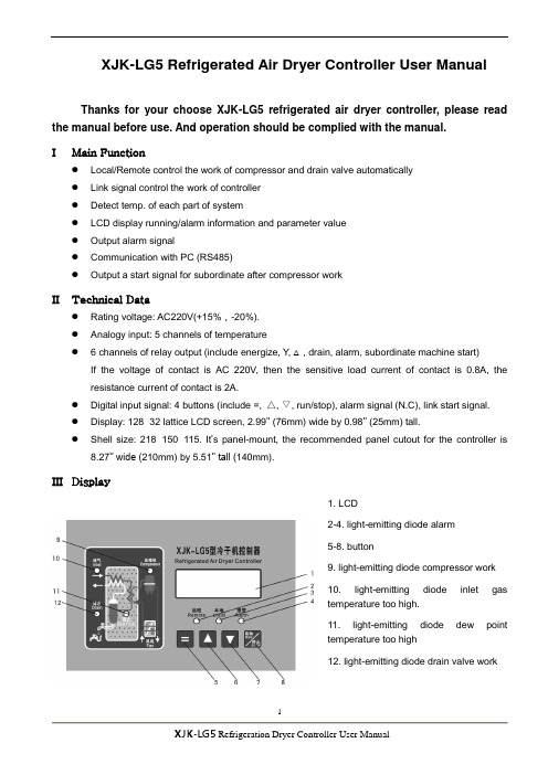
XJK-LG5 Refrigerated Air Dryer Controller User ManualThanks for your choose XJK-LG5 refrigerated air dryer controller, please read the manual before use. And operation should be complied with the manual.I Main Function●Local/Remote control the work of compressor and drain valve automatically●Link signal control the work of controller●Detect temp. of each part of system●LCD display running/alarm information and parameter value●Output alarm signal●Communication with PC (RS485)●Output a start signal for subordinate after compressor workII Technical Data●Rating voltage: AC220V(+15%,-20%).●Analogy input: 5 channels of temperature● 6 channels of relay output (include energize, Y, △, drain, alarm, subordinate machine start)If the voltage of contact is AC 220V, then the sensitive load current of contact is 0.8A, the resistance current of contact is 2A.●Digital input signal: 4 buttons (include =, △, ▽, run/stop), alarm signal (N.C), link start signal.●Display: 128×32 lattice LCD screen, 2.99’’ (76mm) wide by 0.98’’ (25mm) tall.●Shell size: 218×150×115. It’s panel-mount, the recommended panel cutout for the controller is8.27’’ wide (210mm) by 5.51’’ tall (140mm).III Display1. LCD2-4. light-emitting diode alarm5-8. button9. light-emitting diode compressor work10. light-emitting diode inlet gastemperature too high.11. light-emitting diode dew pointtemperature too high12. light-emitting diode drain valve workIV Explanation for parametersTo successfully program this controller, you must first understand how it works and what you are programming into it.Model LG5 controller has 3 class of parameter, class 1 for normal use, class 2 for compensation and other important parameter, class 3 for upper limit of total work time.Note 1: work procedure of drain valve, please see section VI.Note 2: if preset value of ‘return-dew point’> preset value of ‘dew point’, shield dew point take part in control logic.Note 3: after lock time, press ‘RUN/STOP’, output relay of ‘Energize’ and ‘Y’ are closed, compressor start to work, and light-emitting diode 9 (compressor) light. After time of preset of ‘T-switch’, output relay of ‘Y’ is open and output relay of ‘△’ is closed, Y/△connection finished.Note 4: preset value of ‘address’ should be equal to the address set in host monitor software.Note 5: compressor stop work or controller is energized, count down the preset value of ‘lock time’, enter into lock protect state, controller not answer any order.Note 6: after receive the link start signal, controller no start to work immediately, it will delay the time of preset of ‘up delay’.Note 7: if the preset of ‘total’ is 0 means that there is no upper limit for total work time. If the preset is nonzero, and the total work time is up to the preset (LCD is bright, but display nothing, and light-emitting diode 4 twinkles), the controller doesn’t answer any order when restart it. Modify the preset value of ‘total’can make the controller work again.Note 8: the new password should press ‘=’button to make it effective. And next time, input the new password.V ProgramAfter energizing, the controller enters into lock protect state, as figure 10. After lock time, enters to standby state, as figure 8.1) Program class 1 parameterPress ‘=’ button in standby mode to enter into program mode. And the LCD will display as the figure 1. Current parameter value is displayed in black background. Press ‘△/▽‘ button to add or minus the presetvalue. E.g. if the preset value of ‘inlet gas’ displays in black background, means current parameter is ‘inlet gas’, press ‘△/▽‘ button to modify the value. Press ‘△’ button to add, the upper limit of ‘inlet gas’ is 120. Press ‘▽‘ button to minus, the lower limit of ‘inlet gas’ is -19. Press ‘△/ ▽‘ button continually, the value add or minus quickly.Figure 1Press ‘=’ button to choose the next parameter. Show as the figure 2.Figure 2Note 9: if the preset of dew point difference > the preset of dew point, means the dew point is only used to display, and not take part in control.When you finish program and wish to exit program mode, press ‘run/stop’button. Or if there isn’t any press action within 10 seconds, the controller will save changed value and exit program mode automatically.2) Program class 2 parameterPress ‘=’ and ‘△’ buttons at the same time in program mode, LCD displays junior password input screen, as following figure.Figure 3Default password is 666, and can’t be changed. Press ‘△/▽‘button to input correct password. Press ‘=’button to confirm the input password. If it’s right, the LCD will display as figure 4. But if it’s wrong, the LCD will display as figure 1.Figure 4Press ‘=’ button to choose the next parameter, until the LCD display as figure 5.Figure 5Modify the preset value of parameter as class 1 parameter. Press ‘△/▽‘button to add or minus the preset value. Press ‘=’ button to save and return to class 1 parameter setting screen, as figure 1.3) Program class 3 parameterPress ‘=’ and ‘▽‘ buttons at the same time in program mode, LCD displays senior password input screen, as following figure.Figure 6Default password is 888, and it can be changed. Press ‘△/▽‘button to input correct password. Press ‘=’button to confirm the input password. If it’s right, the LCD will display as figure 7. But if it’s wrong, the LCD will display as figure 1.Figure 7Modify the preset value of parameter as class 1 parameter. Press ‘△/▽‘button to add or minus the preset value. Press ‘=’ button to save and return to class 1 parameter setting screen, as figure 1.When senior password is changed, it need to press ‘=’ to confirm, then press ‘run/stop’ to exit the program mode.3) SaveWhen you finish program and wish to exit program mode, press ‘run/stop’button. Or if there isn’t any press action within 10 seconds, the controller will save changed value and exit program mode automatically.VI UseWork procedure of refrigerated air dryer:Press ‘Run/Stop’ button when no alarm signal,refrigerated air dryer start to work, compressor is on. The port of ‘energize’and ‘Y’connected with port ‘COM’(KM1, KM2 are on), LCD displays ‘Main:ON’, and light-emitting diode 9 light. After setting value of ‘T-switch’ (Y-△switch time), ‘Y’ disconnected with port ‘COM’ (KM2 is off) and port ‘△’connected with port ‘COM’ (KM3 is on). Y-△connection swtich procedureis finished, compressor work normally.If compressor doesn’t need Y-△swtich protection, connect the compressor to port ‘energize’ directly. Work procedure of drain valveAfter compressor start to work, controller control drain valve automatically. Delay preset time of ‘Drain OFF’, then open the drain valve for preset time of ‘Drain ON’.Figure 8Start controller:There are three start method. Local start, remote start and link start.Compressor start to work should conform to following condition.①no alarm signal (compressor overload, high pressure alarm, low pressure alarm)②detected dew point ≥ preset value of ‘dew point’Remote control mode: connect port ‘L+’ and port ‘local/remote’ to choose remote control. When controller in work status and choose remote control mode, controller will stop and wait remote start signal. In remote control status, light-emitting diode 2 twinkles and LCD displays ‘Remote: ON’ or ‘Remote OFF’ in leftbake corner. LCD displays as following figure:Figure 9Link start is always valid no matter in local control mode or remote control mode. In local control mode if link start signal is input, light-emitting diode 3 twinkles and LCD displays as figure 10. In remote control mode if link start signal is input, light-emitting diode 2 twinkles in remote control mode, and LCD displays as figure 9.①local start: press ‘Run/Stop’ button, light-emitting diode 3 light, LCD displays as figure 10.Figure 10①Remote start: port ‘L+’ and port ‘local/remote’ are connected, and port ‘L+’ and port ‘remote start’are connected. light-emitting diode 3 light, LCD displays as figure 9.②Link start: when port ‘L+’ and port ‘link signal’ are connected, controller will be started after the time ofsetting of ‘up delay’, .Stop controller:①Press ‘‘Run/Stop’ button to stop controller in any control mode, it has priority.②Disconnect port ‘L+’ and port ‘remote start’ in remote control mode.③Disconnec port port ‘L+’ and port ‘link signal’ if link start signal is input.Controller enters into lock protect mode, LCD displays as figure 11.Figure 11After lock time, controller enters into standby status, LCD displays as figure 12.Figure 12Display other detected temperatureIn running or standby mode, press ‘△’ button to make the LCD display other detected temperature.VII AlarmIn running mode, if alarm signal is input, LCD displays as following. See table 4 for details.Figure 13Note 10: alarm signal type is N.C, so when port ‘L+’ and port ‘Alarm signal’ are disconnected, controller output alarm signal, and LCD displays as figure 13.Inlet gas high temperature alarm:If the temperature of inlet gas is higher than preset value of ‘inlet gas’, light-emitting diode 10 twinkle, and the value will be displayed in black background, as figure 14 shows. And alarm phenomena will be disappear when inlet gas temp. is lower than value of ‘inlet gas’.Figure 14Total work time:If the LCD displays nothing, and the light-emitting diode 4 light, means that the total work time has gotten up to the preset of ‘total time’. Then the controller will not answer any operate action, except enters into program mode and modify the ‘total time’. If the preset of ‘total time’ is ‘0’, means exit this function, the total work time has no time limit.VIII C onnectionSee figure 15 for details.Figure 15。
10~120立方冷冻式干燥机说明书

气出口之间并联旁路管道、中间设截止阀(见图 1-4)以供调试、启动、维修 时使用。
旁路阀
空气出口阀
空气进口阀
图 1-4 旁路阀安装位置
2.3 调试:
本机在出厂时,对制冷系统和控制部分都作了细致的调整和测
试。由于运输、环境、负载等原因,设备安装后,需在现场进行再调试。
备的底部受力搬运。切忌在空气进、出口管道处受力搬运机器。 在离开制造工厂前该设备已经过彻底检查,并装箱,承运商接收时已确认完好无
损。
3.接收 3.1 外观破损检查:如果货物到到达贵方时,有明显损坏,须让承运商在接收单上
注明。 3.2 内在破损检查:当货物到达贵方时表面完好,但开箱时发现有损坏,立即通知
1. 概述: 自然环境下的自由空气经空压机压缩后,其中的水汽、尘埃、油雾等有害物
质随同压缩空气一起被送入用气装置和仪表,毋用多久这种高压气流将对昂贵的 气动装置,仪表及管道造成严重的锈蚀污染、除影响产品以外往往还会因仪表及 装置失准而造成设备人身事故。另外,许多工业如化纤、卷烟、啤酒、钢铁、化 工、橡胶、喷涂、搅拌,气动输送等压缩气直接作用于工序中物料,本身就要求 压缩空气纯净干燥,不允许含水、含油、含尘,所以对压缩空气进一步净化处理 使之达到生产要求已是必不可少的重要手段,采用现代冷冻技术的冷冻式干燥机 和与之配套的精密过滤器是满足这一要求的可靠保证。
3.经空压机通过管道传输到冷冻式干燥机的振动较大时,应在管道中跨接 高压软管消除振动。
4.如果压缩空气中含有大量油污。应在干燥机前加装滤油器。以防止大量 油污进入干燥机,影响干燥机正常工作。
5
Generated by Foxit PDF Creator © Foxit Software For evaluation only.
冷干机XJK-XG1E3产品说明书
XJK-XG1E.3 型微热再生吸干机控制器
露点
设置露点超温报警值
设置露点仪 下限 下限参数
选择露点仪检测范围下限值
设置露点工 上限 作参数 下限
设置露点工作温度上限值 设置露点工作温度下限值
表1
表 1 中的参数按次序分 6 屏分别显示。如图 2 所示。
-99 ~ 99℃ -99 ~ 99℃ -99 ~ 99℃ -99 ~ 99℃
图3 按下“=”键,重新进入设置状态,修改参数值。 2. 一级口令参数设置 z 进入一级口令显示屏 在设置状态下,先按下“=”键不放,然后再按下“△”键,则进入一级密码显示屏,屏幕显示如图 4 所示。一级口令出厂设置为 666(不可更改),按“△”或“▽”输入密码,输入完毕,按“=”确定,如密 码正确,进入一级口令参数设置屏幕,如图 5 所示。如密码错误,则进入图 2 显示屏(设置状态)。
图4
2
杭州新箭电子有限公司
XJK-XG1E.3 型微热再生吸干机控制器
z 可设置参数如表 2 所示
参数设置
参数名称
参数含义
设置范围
设置温度 修正
再生气 进气 露点
设置再生气温度修正值(不用) 设置进气温度修正值(不用) 设置露点温度修正值
-9 ~ 9℃ -9 ~ 9℃ -9 ~ 9℃
延时
设置自启动锁时时间
五、使用方法
z 待机状态: 上电后,正常情况下,液晶显示如图 1 所示,等待启动命令。
z 运行状态: ① 本地运行:
按“启动/停止”键,进入运行状态。启动后,“运行”指示灯常亮,液晶显示如下图所示:
露 点0℃ A塔 无 热 吸 附 30秒
图8 控制器控制四个电磁阀及加热器按时序图一(或时序图二)的次序工作。如图 17,表示 A 塔吸附,吸附 时间倒计时显示。第一行则显示露点温度。 ② 正常停机: 在处于运行状态时,按“启动/停止”键,主机停止工作。 z 远程控制: 将“本地/远控”开关拨至“远控”,远控状态干接点接通,本地控制不起作用。 ① 远程启动: 远控状态下,启动/停止受“远控启动”开关控制。如果加热器正常,即加热器温度没有超过加热器超 温报警值时,允许主机工作。将“远控启动”接通,主机进入运行状态。 ② 远控停机: 远控状态下,在运行状态下,将“远控启动”断开,主机停止工作。 ③ 远控运行指示: 远控运行时,“运行”指示灯闪动显示。
冷冻式干燥机使用说明书

一、安装注意事项: Ⅰ. Notices on Installat音、影响寿命和排 水。
Ⅰ.During installation, the machine shall be placed as horizontally as
possible, since an inclined unit may generate noise and influence the lifetime and drainage.
3、阳光直射会影响冷凝器散热,环境温度不应超过 38℃。雨水淋漓、 潮湿的地方,会造成电气短路、器件生锈。
四、 保护功能………………………………… IV. Protection
五、 日检与保养……………………………… V. Daily Inspection and Maintenance
六、 常见故障…………………………………. VI. Common Failures
七、 电器电路图………………………………. VII. Electrical Circuit Diagram
卷首语
Preface
朋友,感谢你选用了本公司生产的冷冻式压缩空气干燥机。相 信它定能在您的生产线上,为解决压缩空气净化问题助一臂之力。
Dear friends, thank you for choosing the Company’s Refrigeration Compressed Air Drier. We believe that it surely will be helpful in solving the problem of compressed air purification on your lines.
本公司创建几十年来,我们全体同仁,吸取世界各国名厂之精 华,聘请谷轮、松下公司的高级工程师做顾问, 与本公司工程技 术人员通力合作,改良创新, 研究制造的太安伊侨系列产品已广 泛用于化学、机械、轻纺、交通、电子、食品、制药工业等各个 领域 ,深受用户好评。以质量取胜,以服务取信是我们的经营宗 旨!我们真诚的希望您将设备运行中的某些不足和良好建议反馈 我司。并祝安康!
SMC 冷冻式空气干燥机 说明书
1.3.5 关于冷却回路的危险
警告
① 在空气干燥机的冷却配管中,有氟类(HFC)封在其中。 ② 请遵守 1-4 页所示的配置铭板和本服务手册的配置书中所述的氟类的种类及封入量。封入量如果
1-4
2.关于使用
1
使用上的注意事项
2.1 空气干燥机的用途・机种选定
2.1.1 用途
警告
进行维修时,请确认空气干燥机没有使用于下述用途。 ① 不能使用于呼吸器、高压室内、医疗、以及对进入人体的医疗品、食品的吹气。
空气干燥机专用于工业用压缩空气,因此不能使用于此外的情况。不得已使用的情况下,请确认清 楚是否已充分实施了安全对策。 ② 请不要搭载到车辆、船舶上。如果搭载在车辆、船舶等运输装置上,会由于振动而引起破损,从而 导致不能使用。不得以而使用的情况下,请事前与本公司进行确认。 ③ 设计时请考虑到压缩空气停止供给的情况。由于空气干燥机的内部机器等出现故障而引起冻结、压 缩空气不流动的情况都可能发生。 2.1.2 机种选定
1.2 关于本文记载的危险、警告、注意事项 在空气干燥机的安全方面,为了能够实现正确的维修及防止作业者受伤或机器的损坏,本手册根据其严 重性,将危险分为「注意」「警告」「危险」3 个等级进行表示。对这些内容,请认真确认、认真阅读各 注意及警告事项,在充分理解后再对设备进行操作。 「危险」「警告」「注意」是按照严重性由重到轻 的顺序排列的,即(危险>警告>注意)。
2.使用注意事项
2.1 空气干燥机的用途、机种选定
・・・・・ 2-1
冷干机控制说明书

冷冻式干燥机控制说明一、各种负载的控制1、压缩机C首次上电无三分钟延时启动,其他时候压机启动时有三分钟延时。
2、室外风机FM检测冷凝器出口温度T2≥(设定温度+回差温度)时外风机开启,冷凝器出口温度T2≤(设定温度-回差温度)时外风机关闭,回差温度为2度。
3、电磁阀EV检测压机电磁阀温度T3≥设定温度时打开,T3≤(设定温度-5℃)时关闭。
二、保护功能停机保护是指压缩机、风机、电磁阀失电。
1、高压保护功能:正常开机状态下,压机起动20S后检测高压开关。
连续10S检测到高压开关闭合,则进入高压保护,系统停机。
如连续1S检测到高压开关断开,则退出高压故障保护,机组正常运行(可恢复时)。
30分钟内若出现3次高压保护,则非掉电不可恢复,故障显示为“高压保护”。
2、低压保护功能:正常开机状态下,压机起动2分钟后检测低压开关。
连续10S检测到低压开关闭合,则进入低压保护,系统停机。
如连续1S检测到低压开关断开,则退出低压故障保护,机组正常运行。
30分钟内若出现3次低压保护,则非掉电不可恢复,故障显示为低压保护;3、排气温度过高保护:当系统压机开启1分钟后,连续5秒检测到该系统压机排气温度T1≥压缩机高温停机保护设定温度时,则进入压机排气温度过高保护。
当检测到该系统压机排气温度T1≤(压缩机高温停机保护设定温度-20℃)时,则退出压机排气温度过高保护。
30分钟内若出现3次排气温度过高保护,则非掉电不可恢复,故障显示为“超温保护”。
4、过流保护:正常开机状态下,压机起动2分钟后检测过流开关。
连续10S检测到过流开关闭合,则进入过流保护,系统停机。
30分钟内若出现3次过流保护,则非掉电不可恢复,故障显示为“过流保护”。
5、相序保护:开机前,检测相序开关。
检测到相序开关断开,则进入相序保护,系统无法开机。
6、通讯功能:采用标准的Modbus通讯协议,可通过RS485接口与PC机联机进行数据的采集与监控。
7、具有远程启停连锁控制功能三、接线图接线及操作说明:1、温度探头配置:RT1:10K热敏电阻,测温范围(-25℃-125℃),检测压缩机机头温度。
控制器英文说明书(英文面板)
CNC-220S User Manual VER. C-220 0266 /0268/0288/0399/ect.DOC NO:020129 Page1of 18迈维自動化有限公司maiwei AUTOMATION CO.,LTD.CONTENTS1. INTRODUCTION (2)2. MAIN FEATURES (2)3. FRONT PANEL DESCRIPTION (3)4. PROGRAMMING WINGING PARAMETER (5)5. WINDING METHOD DESCRIPTION (6)6. WINDING EXECUTION (8)7. CONFIGURATION SETTING (9)8. INSTALLATION AND WIRING (11)9. ADJUSTMENT (14)10. MAINTAIN AND TROUBLESHOOTING (15)迈维自動化有限公司maiwei AUTOMATION CO.,LTD.1. INTRODUCTIONCNC-220S is a series of COIL WINDING MACHINE CONTROLLERdeveloped by MAIWEI AUTOMATION . It not only retains all the features ofprevious designs, it also has a low noise level and is less sensitive to externalpower fluctuation.CNC-220S also features an integrated design: putting stepper motor driver,DC motor speed controller, brake and power supplier control circuits into onecontrol box, simultaneously achieving size reduction, high performance andlow cost.CNC-220S Series offers CNC-220S “Standard Model” and CNC -220S EXD"External Connection Model”, depending on whether a close -loop driver isprovided for various applications.2. MAIN FEATURES◆ Single chip DSP Microprocessor design, has further higher performance and higher functions; it also has less sensitive to external power fluctuation orto external electromagnetic interference.◆ Memory capacity capable storing up to 0- 1000 steps winding data, 9 winding parameters, and 5 options can be independentlyassigned for each step. Off-power memory retention without battery.◆ Winding speed can be specified using the front panel keypad, resulting ineasy programming of multi-step, multi-speed settings.◆ Guiding traverse shaft stepper motor with a constant-current driver offeringfast wire guiding speeds.◆ Power input AC100V~120V 、220V~240V 600VA(max).迈维自動化有限公司maiwei AUTOMATION CO.,LTD.3. FRONT PANEL DESCRIPTION3.1. Power switchPower:Power supplier equipped, controls the AC power to the controller.3.2. Key pads0-9:10 key, for entering numerical values.『QTY SET』:Enter into EDIT mode.『EDIT』:Specify target production quantity.『START STEP』:Specify starting step in memory.『END STEP』:Specify ending step in memory.『DATA SEL』:Select parameter to be programmed, or to switch display mode. 『FEED DIR』:Select guiding direction for each step.『WIND DIR』:Select winding direction for each step.『EDGE STOP』:To specify whether to suspend winding when the guiding traverse moves to the two edges of the width.『AUTO HOME』:Select whether to have auto-positioning function for each step. 『AUTO START』:Select whether to have auto-starting function for each step. 『-』:Reduce step number by one, or reduce PIECE COUNTER by one.『CLR』:During programming, clear current data to zero.『COPY』:Copy the data of previous step into current step.『ENT』:Write data into memory.『RPM』:Switch display to shows PIECE COUNT or RPM.『ZERO』:Hold down this key for two seconds to reset PIECE COUNTER to zero. 『AUTO』:To switch between AUTO and NON-AUTO mode.『BRAKE』:Switch whether brake will be applied to the win spindle during stopping.迈维自動化有限公司maiwei AUTOMATION CO.,LTD.『NEXT』:Skip current step and go to the next step.『PREV IOUS』:Discard current step and go to the previous step『RESET』:At any time, discontinues current operation and return to ready mode. 『STOP』:Pause during winding.『START』:Restart during pause, or pause during winding.←:guiding traverse moves to the left.→:guiding traverse moves to the right.:Show the current step number being wound or beingprogrammed.:During programming, in combination with LED, shows the parameter being programmed. During winding or ready mode, show thecurrent number of turns or show the guiding traverse shafts position.Shows PIECE COUNT or RPM.3.4. Status indicators□READY: lit means in READY mode, flash means PAUSE mode ,not litmeans winding or programming in progress.□RUN: lit means winding in progress; not lit means not in progress.□SLOW: during winding, lit means low speed winding; not lit means high speed winding.□MOVE: lit means guiding traverse is fixing the starting position forwinding or is returning to the home position.□O.S: lit means winding operation is over speeding, guiding traverseand winding spindle shaft are out of synchronization.□LAN: lit means currently communicating with network.□FINISH: will lit when reaching the preset piece count.□ RPM: lit means the PIECE COUNT DISPLAY shows RPM.□ QTY: lit means the PIECE COUNT DISPLAY shows the piece count.3.5. Winding parameters definitions□SHIFT : Starting position of the guiding traverse.[Setting range 0.00~ 999.99 mm].□WIDTH : The traverse of the copper wire led by the traverse duringwinding. [Setting range 0 ~999.99 mm].□PITCH : Diameter of the copper wire. [Setting range 0~ 9.999mm].□TURNS: Total number of turns to be wound.[Setting range 0.0~9999.9 or 0~99999 turns].□S.SLOW : Number of turns to be wound at low speed, when start winding.[Setting range 0~999.9 turns].□E.SLOW : Number of turns to be done at low speed prior to stopping.[Setting range 0 ~999.9 turns].□H.S.: High winding speed. [Setting range from 0~99%].□L.S. : Low winding speed. [Setting range from 0~25%].□FUN : Winding complete output signal setting.4. PROGRAMMING WINGING PARAMETER4.1. MEMORY RANGE SELECTIONCNC-220S contains 1000 memory step, By defining the region, users caneffectively manage the memory. Various winding parameter can be stored indifferent regions and can be retrieved instantaneously. After specifying theregions, programming and winding can be done in those regions; allun-selected regions will retain their original contents and unmodified. Whensetting the STEP number, the Ending step number must be larger than theStarting step number, or the winding operation will not startSpecifying starting stepIn ready mode, press to select. [Setting range 0 ~ 999].Specifying ending stepIn ready mode, press to select. [Setting range 0 ~ 999].4.2. Programming winding parameterIn “READY” mode, press invokes the programming mode. First the“START STEP” number will shows at “Procedures displayer”, the parameter indicator 『SHIFT』will lit, the starting position will shows at “Documents dispayer”. The starting position can be changed to the new position by pressing thenumerical keys followed by the key.After that the STEP number will automatically increase by one, to continue setthe starting position for next step. When the STEP number larger then the“END STEP”number, the STEP number will restore to the “START STEP”number and the indicator light will change from『SHIFT』to 『WIDTH』foruser to specifying the width for each STEP. Repeat the same procedure using numerical keys and the key, all winding parameters for each STEP canThe following functions are also available::To select guiding direction, forward or reverse.:To select winding direction, clockwise or counter-clockwise.:To specify whether to suspend winding when the guiding traversemoves to the two edges of the width.:To select whether guiding traverse returns to the starting positionautomatically or upon a manual pressing of the key.:Select whether to have auto-starting function for each step.:Clear the current value to zero.copy:Copy the content of the previous step to the current step.—:Go back to the previous programming step.:To scroll through different parameters.Each time when change the PARAMETER or OPTIONS, key mustpressed to effect the change.4.3. Guiding traverse shaft introduce settingDuring set the 『SHIFT』, 『WIDTH』and 『guiding traverse travel limit』,can use numeric keypad to set location data or can also use ,←or→keysTo leading the guiding traverse shaft location.4.4. Clear all winding parameterIn the”READY”mode, press will clear all the winding parameter inthe memory. Be cautious in using this function or all the data will be lost. 5. WINDING METHOD DESCRIPTIONPrior to winding, the general winding principles are explained below so the operators can have a better understanding of the performance of the controller and make better use of it.5.1. Counting mode(Refer to the section 7.1. Counting mode).◆Absolute counting modeWinding spindle shaft is capable of fixed-point stopping. Upon each restart,the turn count will reset only the integer portion of the turn’s to zero, with the decimal unchanged. For example, for a previous number of 100.3 turns, when restarting the next step winding, the counting will start with 0.3 turn to avoid accumulation of spindle shaft free play error from consecutive windings. This counting method may cause insufficient winding by one turn. Therefore, when starting from 0.5~0.9, the spindle will turn to the 0.0 before it starts counting.◆Relative counting modeThis counting method zeros the counter upon each restart, therefore it is easy to understand and will not cause insufficient winding.5.2. Wire-guiding mode◆Interlace wire-guidingIf the『幅宽』of the step is zero, the wire-guiding becomes interlace mode. When it begins winding, the wire-guiding will follow the wire direction to proceed two wire diameters and regress one wire diameters cyclically until the step of winding ends. This mode especially suits the inductor winding.◆Non wire-guidingSometimes, the winding device may be used to winding adhesive tapes or copper foil. When the wire-guiding is not needed, 『PITCH』may be adjusted to zero and the wire-guiding won't be move.5.3. Operation mode(Refer to the section 7.1. Operation mode).◆Single click modeWhen press the start switch, the motor start winding, and when you releasethe start switch, the motor stop winding immediately.◆Double click modeWhen press the start switch, the motor start winding, and if you want to pause the motor, you have to release the start switch then press it again.5.4. Running mode◆Continual modeBefore it begins winding, if『SHIFT』of the step set as 999.99, then the starting position, the width , the wire-guiding direction and the winding direction won't be re-read. The values are not changed, that is the wire guiding will continue guiding wires on the same position. The width and left-right margins are the same as the ones of the previous section. Both the wire-guiding and winding directions are not changed either. This mode especially suits to winding which have the multiple drawing tops in the same sets of coils.◆Edges slow modeThe winding speed will slow down before the guiding traverse reach to the two edges of the width (work with『E.SLOW』turns). After the guiding traverseCNC-220S USER MANUAL VER. Page 8 of 18迈维自動化有限公司maiwei AUTOMATION CO.,LTD.veered, then restore to hi-speed winding. (Refer to the section 7.1. edge slow mode).◆Automatically circularly modeIf key set to on, it means Automatically circularly mode, in this modewhen finish a step of winding it will automatically get into next step and start winding without press key (work with and keys).5.5. How to Correct setting turns◆Preset methodSet the 『E.SLOW』to zero first and then set the 『TURNS』to the desired number. Set proper parameters according to copper wire, bobbin, tension, etc, then press to start winding. When finished, obtain the actual number ofturns and calculate the number of overshot turns. Go into programming modeand subtract the number of the overshot turns from the 『TURNS』to obtainthe required setting.This method has a higher throughput, however, the resulting stopping location may not be precise.◆High-Low speed methodThis method uses a combination of 『H.S.』/『L.S』and 『E.SLOW』to achieve the desired number of turns.The『L.S.』should not be too high. The number of 『E.SLOW』turns must be adequate to allow the spindle shaft to slow down to low speed before reachingthe total number of turns. This can result in precise stopping location.◆Double-brake methodAs the winding turns of the winding shaft reach the numbers of the『E.SLOW』, brake for a short period first. After the winding shaft stops, continue winding atlow speed. Therefore the numbers of the slow speed may be reduced and the efficiency of winding may be increased, (Refer to the section 7.1. braking mode).6. WINDING EXECUTION6.1. To start windingAfter set up all data items, press key,the winding process begins in accordance with the set-up content. Press key to pause winding. During winding, press the key, the winding speed can be switch between highspeed and low speed.The following key functions are available during PAUSE mode::Give up the numbers of the winding turns and regress one step.:Finish current step and proceed to next step.CNC-220S USER MANUAL VER. Page 9 of 18迈维自動化有限公司maiwei AUTOMATION CO.,LTD.Continue winding.: Give u p winding and go back to the”READY ”mode.6.2. Change the display modeDuring winding or during PAUSE mode, press key, the“Documents displayer ” can be change the display mode between turns or guiding traverse position.6.3. Winding speed (RPM) displayPress ing key will cause the”QTY displayer ” to display the spindleshaft “RPM ” without interrupting the counting. Pressing again will change the“QTY displayer ” back to displaying the piece count.6.4. Piece counter managementUpon turning on the “POWER ”, “QTY displayer ” will showsthe number of piece produced. During wining, each time the CONTROLLERgoes from the “Stert step ” to the “End step ”, the piece counter willautomatically increase by one.◆ Preset piece counterIn “ready ” mode, press key once and key in desired values followedby the key. When the “QTY displayer ”reaches the preset value, theFINISH led will lit. [Setting range 0~99999].◆ Decrease piece counterDuring “READY ”or PAUSE mode, press the key and hold down for twoseconds the piece counter will decrease by one.◆ Reset piece counterIn any time holding down key for two seconds, it will set the piececounter to zero.7. CONFIGURATION SETTINGCNC-220s is a multi-purpose design, to meet various requirements;additional settings are configured to provide flexibility for additionalapplications.In the “READY ” mode, press the following keys combination as section[7.1.~7.8], the “Documents displayer ” will show corresponding setting value. If no change is necessary, press the key get back to “READY ” mode. Orpress key to get into change mode, then the parameter can be changed bypressing the numerical key followed by the key. 7.1. Winding mode selection 『EDIT 』 『DATA SEL 』In this function the STEP display and the DATA display will shows eight digits, representing eight winding mode selections respectively.Press numerical keys as below to set each digit.CNC-220S USER MANUAL VER. Page 10 of 18邁維自動化有限公司maiwei AUTOMATION CO.,LTD.7 6 5 4 3 2 1 :The guiding traverse moving speed.0 represents high speed ; 1 represents low speed.2 Moving increment :The travel increment of the guiding traverse.1 represent 0.01mm (4 mm per revolution).2 represent 0.02mm (8 mm per revolution).3 represent 0.01mm (5mm per revolution).4 represent 0.04mm(16 mm per revolution. 3Counting mode :Select the counting mode of the winding spindle shaft. 0 represents with zero point and using absolute counting mode.1 represents without zero point and using relative counting mode. 4Edge slow :Slow down the winding speed before the guiding traverse reach to the two edges of the width.0 represents not slow down ; 1 represents to slow down. 5Braking mode :Select the braking mode of the winding spindle. 0 represents single brake mode ; 1 represents double brake mode. 6Counting unit :Select 0.1 or 1 turns as your count unit. 0 represents 0.1(0.0 to 9999.9 turns); 1 represents 1(0 to 99999 turns). Guiding traverse unit :Select the basic unit of guiding traverse.0 represents mm; 1 represents inch (must using lead screw in imperial). Operation mode :Select operation mode for the START switch.0 represents Single click mode ; 1 represents Double click mode.The key on the front panel always as the Double click mode.7.2. Password 『EDIT 』 『DATA SEL 』 2This password is used to protect the setting data in memory. After you set this password, you cannot change any winding parameter and configuration data in normal sequence. You have to key in four numbers of password before press the ,『ENT 』『START STEP 』,『END STEP 』,『QTY SET 』 keys. If the password has been passed once, youcan change any data in normal sequence until you turn off the power or press key. You must to remember the password or you cannot change any data.[Setting range 0000~9999]. Set 0000 means no password.7.3. Travel limit 『EDIT 』 『DATA SEL 』 3Set the maximum travel distance of guiding traverse. During winding when the guiding traverse reaches this position, the motor stop winding immediately,and the “Documents displayer ” shows error massage, then “RESET ” and goback to the“READY ” mode. [Setting range 000.00~999.99]. 999.99 Means no limit. 7.4. Fixed location 『EDIT 』 『DATA SEL 』 4To set how often, must be correct the guiding traverse location. Each time when finish this number of product pieces, the guiding traverse will moves to the home position to correct the location before moving to starting position. [Setting range 00~ 99]. Set 00 means not to do this function.7.5. Limited winding speed 『EDIT 』 『DATA SEL 』 5 This value is to limited winding speed and make sure the winding spindle shaft and guiding traverse are in synchronization. The controller uses this value to calculate with wire PITCH of current step, and then to limited maximum winding speed of current step.[Setting range 0~ 99999]. Set 0 means no limit speed.7.6. Brake holding time 『EDIT 』 『DATA SEL 』 6 To set the hold times for brake. [Setting range 0.1~9.9 sec].7.7. Acceleration times 『EDIT 』 『DATA SEL 』00 means shortest acceleration times ;99 means longest acceleration times. 7.8. Deceleration times 『EDIT 』 『00 means shortest deceleration times ;99 means longest deceleration times.8. INSTALLATION AND WIRING◆The controllers should be operated in an environment that is protected from moisture, corrosive gases, or liquid, and free from airborne dust, metallic particles, and magnetic noise.◆Do not block the intake/exhaust ports of the controller. Otherwise, a fault may occur.◆Make sure that the power source supplies the correct voltage and is capable of supplying the required current to the controllers.◆Do not connect or disconnect wires and connectors while power is applied to the controller.Make sure the machine and controllers are properly grounded. Make sure that the leads and connectors are connected correctly.◆Normally operate under 10℃ ~ 40℃ environment ; over 40℃ should perform under good ventilation, avoid heating.8.2. Wiring diagram for CN3~CN6FOOT SWITCH Operate Switches Home Sensor Turn Counter AUX I/O邁維自動化有限公司maiwei AUTOMATION CO.,LTD.8.3. Wiring diagram for CNC-220SAC Input DC90-180V/90-400W DC24V 12W 2Phase 6V 2ADC MOTOR BRAKE STEP MOTOR Drive STEP Motor in directlyAC Input Motor Driver DC24V 12W 2Phase 6V 2ABRAKE STEP MOTOR External connect STEP Motor driver邁維自動化有限公司maiwei AUTOMATION CO.,LTD.AC Input Motor Driver DC24V 12W Step Motor DriverBRAKE9. ADJUSTMENT9.1. Adjustments for CNC-220SACC: Acceleration timesRotate ACC to set the accelerate times for the winding spindleCL:Output current limit.1. Connect a DC Amperes meter between terminal and DC motor as below.2. In ready mode press to make the DC motor starting rotate andthen press to holding the winding spindle.3. Rotate CL to set limited current, show on Amperes meter.( 2A for 180v DC motor、4A for 90v DC motor).(The CL have been set by factory before delivery. Only adjust it when change DC motor and replace 220-DVR driver board.)IR:Torque compensation.1. Set the winding parameter “H.S”、”L.S”. in 20, then press to change the DISPLAY shows RPM. Then press key to start winding.2. Rotate IR potentiometer to make it in same speed during the winding spindle shaft in full-load and unload. Then press key to stop winding.MAX:Maximum winding speed.3. Set the winding parameter“H.S”、”L.S”. in 99, and press key to change the DISPLAY shows RPM. Then press key to start winding.4. Rotate MAX potentiometer to make the winding speed (RPM) as you wantThen press key to stop winding.CNC-220S CNC-220S EXD9.2. Adjustments for CNC-220S EXDSpeed Mode selectionTo select the speed signal output mode for winding driver.Selected by JP1.1. Vout mode:Represents the speed signal with DC 0~10v output.2. H/L mode:Represents the speed signal with HI/LOW lever output.Hi speed with HI lever, low speed with LOW lever.Vout adjust1. Set the winding parameter “H.S”、”L.S”.in 99, and press“MAX” key to change the DISPLAY shows RPM. Then press key to start winding.2. Rotate Vout potentiometer to make the winding speed (RPM) as you want.Then press key to stop winding.3. This function only worked in Vout mode.110.MAITAIN AND TROUBLESHOOTING110.1. Periodically maintain◆Please periodically clean up the controller inner accumulate dust and dopants.◆Please periodically check the wire connection between controller and machine if have loose or bad contact.◆The following parts must be maintained or changed periodically as listbelow. If any part is found faulty, it must be changed immediately evenwhen it has not yet reached the end of its life, which depends on theoperating method and environmental condition.◆For parts replacement, please contact your sales representative.10.2. Error messageWhen a fault occurs during operation, the DATA DISPLAY shows errormassage, stop wi nding and then “RESET”go back to the “READY” mode.Err-0:The parameters or data in memory are fault.Err-1:The『SHIFT』value sets exceed the Travel Limit.Err-2:During winding, the guiding traverse to exceed the Travel Limit.Err-3:During winding, the guiding traverses reach to the Home sensor.10.3. To abort seeks the original positionAt boot and reset procedures, if because of unknown reason howeverengender the winding shaft and guiding traverse can't find out the originalposition and make the controller can't get into ready mode, can press keyto abort seeks the original position, make controller get into ready mode.10.4. TroubleshootingThis section provides information to guide the user in understanding differentfault condition and their general troubleshooting procedures, and with their possible solutions.◆Do not connect or disconnect wires and connectors while power is appliedto the controller.◆Make sure that the leads and connectors are connected correctly, beforedoing the troubleshooting procedures.◆Do not remove welded parts on the PC board without appropriate tools.CNC-220S USER MANUAL VER. Page 17 of 18邁維自動化有限公司maiwei AUTOMATION CO.,LTD.CNC-220S USER MANUAL VER. Page 18 o18邁維自動化有限公司maiwei AUTOMATION CO.,LTD.。
冷冻干燥机-ALPHA 1-4 LSC
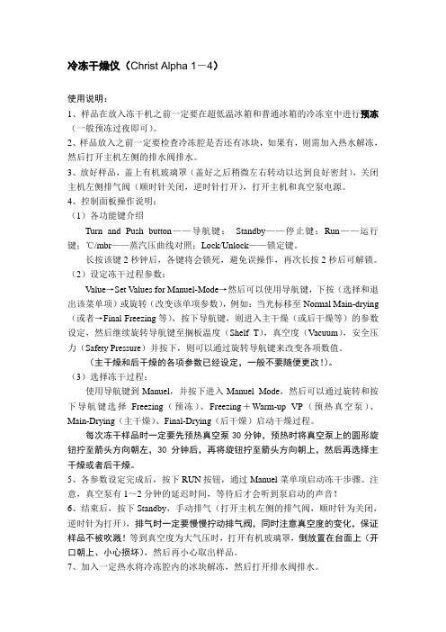
冷冻干燥仪(Christ Alpha 1-4)使用说明:1、样品在放入冻干机之前一定要在超低温冰箱和普通冰箱的冷冻室中进行预冻(一般预冻过夜即可)。
2、样品放入之前一定要检查冷冻腔是否还有冰块,如果有,则需加入热水解冻,然后打开主机左侧的排水阀排水。
3、放好样品,盖上有机玻璃罩(盖好之后稍微左右转动以达到良好密封),关闭主机左侧排气阀(顺时针关闭,逆时针打开),打开主机和真空泵电源。
4、控制面板操作说明:(1)各功能键介绍Turn and Push button——导航键;Standby——停止键;Run——运行键;℃/mbr——蒸汽压曲线对照;Lock/Unlock——锁定键。
长按该键2秒钟后,各键将会锁死,避免误操作,再次长按2秒后可解锁。
(2)设定冻干过程参数:V alue→Set Values for Manuel-Mode→然后可以使用导航键,下按(选择和退出该菜单项)或旋转(改变该单项参数),例如:当光标移至Normal Main-drying (或者→Final Freezing等),按下导航键,则进入主干燥(或后干燥等)的参数设定,然后继续旋转导航键至搁板温度(Shelf T),真空度(V acuum),安全压力(Safety Pressure)并按下,则可以通过旋转导航键来改变各项数值。
(主干燥和后干燥的各项参数已经设定,一般不要随便更改!)。
(3)选择冻干过程:使用导航键到Manuel,并按下进入Manuel Mode,然后可以通过旋转和按下导航键选择Freezing(预冻)、Freezing+Warm-up VP(预热真空泵)、Main-Drying(主干燥)、Final-Drying(后干燥)启动干燥过程。
每次冻干样品时一定要先预热真空泵30分钟,预热时将真空泵上的圆形旋钮拧至箭头方向朝左,30分钟后,再将旋钮拧至箭头方向朝上,然后再选择主干燥或者后干燥。
5、各参数设定完成后,按下RUN按钮,通过Manuel菜单项启动冻干步骤。
- 1、下载文档前请自行甄别文档内容的完整性,平台不提供额外的编辑、内容补充、找答案等附加服务。
- 2、"仅部分预览"的文档,不可在线预览部分如存在完整性等问题,可反馈申请退款(可完整预览的文档不适用该条件!)。
- 3、如文档侵犯您的权益,请联系客服反馈,我们会尽快为您处理(人工客服工作时间:9:00-18:30)。
XJK-LG5 Refrigerated Air Dryer Controller User ManualThanks for your choose XJK-LG5 refrigerated air dryer controller, please read the manual before use. And operation should be complied with the manual.I Main Function●Local/Remote control the work of compressor and drain valve automatically●Link signal control the work of controller●Detect temp. of each part of system●LCD display running/alarm information and parameter value●Output alarm signal●Communication with PC (RS485)●Output a start signal for subordinate after compressor workII Technical Data●Rating voltage: AC220V(+15%,-20%).●Analogy input: 5 channels of temperature● 6 channels of relay output (include energize, Y, △, drain, alarm, subordinate machine start)If the voltage of contact is AC 220V, then the sensitive load current of contact is 0.8A, the resistance current of contact is 2A.●Digital input signal: 4 buttons (include =, △, ▽, run/stop), alarm signal (N.C), link start signal.●Display: 128×32 lattice LCD screen, 2.99’’ (76mm) wide by 0.98’’ (25mm) tall.●Shell size: 218×150×115. It’s panel-mount, the recommended panel cutout for the controller is8.27’’ wide (210mm) by 5.51’’ tall (140mm).III Display1. LCD2-4. light-emitting diode alarm5-8. button9. light-emitting diode compressor work10. light-emitting diode inlet gastemperature too high.11. light-emitting diode dew pointtemperature too high12. light-emitting diode drain valve workIV Explanation for parametersTo successfully program this controller, you must first understand how it works and what you are programming into it.Model LG5 controller has 3 class of parameter, class 1 for normal use, class 2 for compensation and other important parameter, class 3 for upper limit of total work time.Note 1: work procedure of drain valve, please see section VI.Note 2: if preset value of ‘return-dew point’> preset value of ‘dew point’, shield dew point take part in control logic.Note 3: after lock time, press ‘RUN/STOP’, output relay of ‘Energize’ and ‘Y’ are closed, compressor start to work, and light-emitting diode 9 (compressor) light. After time of preset of ‘T-switch’, output relay of ‘Y’ is open and output relay of ‘△’ is closed, Y/△connection finished.Note 4: preset value of ‘address’ should be equal to the address set in host monitor software.Note 5: compressor stop work or controller is energized, count down the preset value of ‘lock time’, enter into lock protect state, controller not answer any order.Note 6: after receive the link start signal, controller no start to work immediately, it will delay the time of preset of ‘up delay’.Note 7: if the preset of ‘total’ is 0 means that there is no upper limit for total work time. If the preset is nonzero, and the total work time is up to the preset (LCD is bright, but display nothing, and light-emitting diode 4 twinkles), the controller doesn’t answer any order when restart it. Modify the preset value of ‘total’can make the controller work again.Note 8: the new password should press ‘=’button to make it effective. And next time, input the new password.V ProgramAfter energizing, the controller enters into lock protect state, as figure 10. After lock time, enters to standby state, as figure 8.1) Program class 1 parameterPress ‘=’ button in standby mode to enter into program mode. And the LCD will display as the figure 1. Current parameter value is displayed in black background. Press ‘△/▽‘ button to add or minus the presetvalue. E.g. if the preset value of ‘inlet gas’ displays in black background, means current parameter is ‘inlet gas’, press ‘△/▽‘ button to modify the value. Press ‘△’ button to add, the upper limit of ‘inlet gas’ is 120. Press ‘▽‘ button to minus, the lower limit of ‘inlet gas’ is -19. Press ‘△/ ▽‘ button continually, the value add or minus quickly.Figure 1Press ‘=’ button to choose the next parameter. Show as the figure 2.Figure 2Note 9: if the preset of dew point difference > the preset of dew point, means the dew point is only used to display, and not take part in control.When you finish program and wish to exit program mode, press ‘run/stop’button. Or if there isn’t any press action within 10 seconds, the controller will save changed value and exit program mode automatically.2) Program class 2 parameterPress ‘=’ and ‘△’ buttons at the same time in program mode, LCD displays junior password input screen, as following figure.Figure 3Default password is 666, and can’t be changed. Press ‘△/▽‘button to input correct password. Press ‘=’button to confirm the input password. If it’s right, the LCD will display as figure 4. But if it’s wrong, the LCD will display as figure 1.Figure 4Press ‘=’ button to choose the next parameter, until the LCD display as figure 5.Figure 5Modify the preset value of parameter as class 1 parameter. Press ‘△/▽‘button to add or minus the preset value. Press ‘=’ button to save and return to class 1 parameter setting screen, as figure 1.3) Program class 3 parameterPress ‘=’ and ‘▽‘ buttons at the same time in program mode, LCD displays senior password input screen, as following figure.Figure 6Default password is 888, and it can be changed. Press ‘△/▽‘button to input correct password. Press ‘=’button to confirm the input password. If it’s right, the LCD will display as figure 7. But if it’s wrong, the LCD will display as figure 1.Figure 7Modify the preset value of parameter as class 1 parameter. Press ‘△/▽‘button to add or minus the preset value. Press ‘=’ button to save and return to class 1 parameter setting screen, as figure 1.When senior password is changed, it need to press ‘=’ to confirm, then press ‘run/stop’ to exit the program mode.3) SaveWhen you finish program and wish to exit program mode, press ‘run/stop’button. Or if there isn’t any press action within 10 seconds, the controller will save changed value and exit program mode automatically.VI UseWork procedure of refrigerated air dryer:Press ‘Run/Stop’ button when no alarm signal,refrigerated air dryer start to work, compressor is on. The port of ‘energize’and ‘Y’connected with port ‘COM’(KM1, KM2 are on), LCD displays ‘Main:ON’, and light-emitting diode 9 light. After setting value of ‘T-switch’ (Y-△switch time), ‘Y’ disconnected with port ‘COM’ (KM2 is off) and port ‘△’connected with port ‘COM’ (KM3 is on). Y-△connection swtich procedureis finished, compressor work normally.If compressor doesn’t need Y-△swtich protection, connect the compressor to port ‘energize’ directly. Work procedure of drain valveAfter compressor start to work, controller control drain valve automatically. Delay preset time of ‘Drain OFF’, then open the drain valve for preset time of ‘Drain ON’.Figure 8Start controller:There are three start method. Local start, remote start and link start.Compressor start to work should conform to following condition.①no alarm signal (compressor overload, high pressure alarm, low pressure alarm)②detected dew point ≥ preset value of ‘dew point’Remote control mode: connect port ‘L+’ and port ‘local/remote’ to choose remote control. When controller in work status and choose remote control mode, controller will stop and wait remote start signal. In remote control status, light-emitting diode 2 twinkles and LCD displays ‘Remote: ON’ or ‘Remote OFF’ in leftbake corner. LCD displays as following figure:Figure 9Link start is always valid no matter in local control mode or remote control mode. In local control mode if link start signal is input, light-emitting diode 3 twinkles and LCD displays as figure 10. In remote control mode if link start signal is input, light-emitting diode 2 twinkles in remote control mode, and LCD displays as figure 9.①local start: press ‘Run/Stop’ button, light-emitting diode 3 light, LCD displays as figure 10.Figure 10①Remote start: port ‘L+’ and port ‘local/remote’ are connected, and port ‘L+’ and port ‘remote start’are connected. light-emitting diode 3 light, LCD displays as figure 9.②Link start: when port ‘L+’ and port ‘link signal’ are connected, controller will be started after the time ofsetting of ‘up delay’, .Stop controller:①Press ‘‘Run/Stop’ button to stop controller in any control mode, it has priority.②Disconnect port ‘L+’ and port ‘remote start’ in remote control mode.③Disconnec port port ‘L+’ and port ‘link signal’ if link start signal is input.Controller enters into lock protect mode, LCD displays as figure 11.Figure 11After lock time, controller enters into standby status, LCD displays as figure 12.Figure 12Display other detected temperatureIn running or standby mode, press ‘△’ button to make the LCD display other detected temperature.VII AlarmIn running mode, if alarm signal is input, LCD displays as following. See table 4 for details.Figure 13Note 10: alarm signal type is N.C, so when port ‘L+’ and port ‘Alarm signal’ are disconnected, controller output alarm signal, and LCD displays as figure 13.Inlet gas high temperature alarm:If the temperature of inlet gas is higher than preset value of ‘inlet gas’, light-emitting diode 10 twinkle, and the value will be displayed in black background, as figure 14 shows. And alarm phenomena will be disappear when inlet gas temp. is lower than value of ‘inlet gas’.Figure 14Total work time:If the LCD displays nothing, and the light-emitting diode 4 light, means that the total work time has gotten up to the preset of ‘total time’. Then the controller will not answer any operate action, except enters into program mode and modify the ‘total time’. If the preset of ‘total time’ is ‘0’, means exit this function, the total work time has no time limit.VIII C onnectionSee figure 15 for details.Figure 15。