ROBA-stop电磁安全制动器说明书
ROBA制动器系统说明
and minimises the endangerment of people and machines. These brakes are used as safe single brakes for protection according to the Danger Category 2 or as a component of a redundant safety system (Category 3), as well as for independent, redundant dual circuit brake systems.
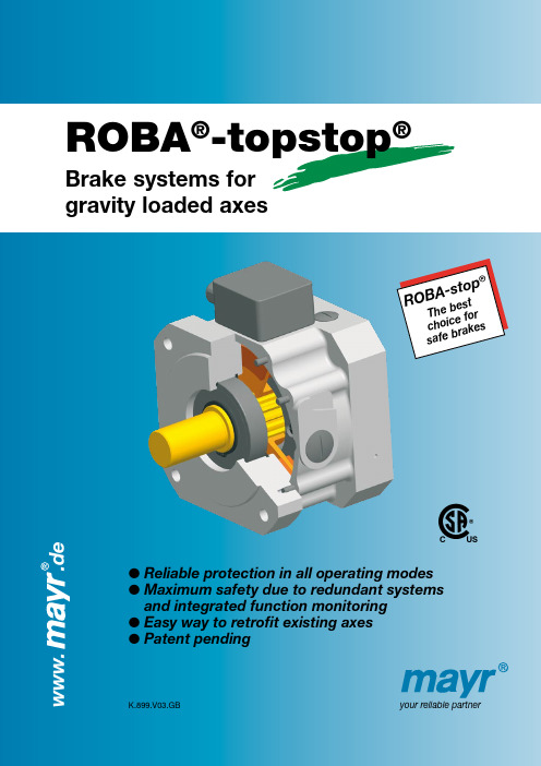
Safe brake systems for gravity loaded axes
mayr® ROBA-stop® brakes prevent unintentional vertical axes drops or crashes!
❒ Reliable safety protecting people in all operating modes
and integrated function monitoring l Easy way to retrofit existing axes l Patent pending
K.899.V03.GB
your reliable partner
www.
Perfect brakes for vertical axes
ROBA®-topstop®
Brake systems for gravity loaded axes
ROBsTcahhAfoee-icbsbeertasoftokper®s
.de
C C USUS
l Reliable protection in all operating modes l M aximum safety due to redundant systems
ABB智能电磁闸技术说明书
1VAL0003-TN Rev A—TECHNICAL NOTEABB smart coil technology, programing and EMC testingProduction of certain ABB medium voltage circuit breakers employs smart coil switch technology (SmartCS). The SmartCS functions in a circuit as an older style coil would, except with added benefits for monitoring and increased reliability as opposed to a standard coil.The smart coil has a high impedance input due to the onboard electronics. This high impedance gives the device a lower current draw than conventional coils thus having a higher than expected voltage drop (~60 V for 125 V system) across the coil during coil supervision. The reduced power consumption (<100 mA @125 V) of the SmartCS during supervision make it suitable for constant 24/7 monitoring with the main device in the open or closed position. This also leads to a reduced battery bank size when used with backup systems.Additionally, SmartCS has a much faster response time than a standard coil in that it triggers off a voltage threshold for actuation where standard coils require a large current increase in the circuit to create the necessary magnetic force for activation. ABB SmartCS is used in the following MV products:·eVD4 (Vacuum CB with embedded IED RBX615)·GSec (Indoor SF6-Isulated Load Break Switch)·HD4 (SF6 – MV primary distribution)·HD4/R (SF6 CB – MV secondary distribution)·VD4 (Vacuum CB - MV primary distribution)·VD4 ANSI (ANSI version of VD4 - ADVAC)·VD4 HD 40kA with Twin EL·VD4/R (Vacuum CB - MV secondary distribution)·VMAX (Vacuum CB)·VMAX ANSI (ANSI version of VMAX)The SmartCS is composed of two parts:·Electromagnetic coil·Electronic board enclosed in a plastic box.During manufacture of the electronic board, the main operating program for the SmartCS is flashed on to the processor and can never be updated or changed for the life of the coil except for 12 configurable parameters. This ABB proprietary firmware performs all on board monitoring and control functions during operation. The functions performed for increased reliability are as follows:·Noise immunity·Watchdog timer of controller·Fast time response i.e. coils operate off voltage and not current·Controls coil current for a specific magnetic force independent of voltage and temperature·Impedance checks of coil winding and electronic circuits·Over-current, short-circuit and over temperature protectionsThe SmartCS has a single two pin input (middle third pin not used) which is used for both programing of reconfigurable settings and operation after the coil has beenassembled. This input consists of four ports as seen below.Power supplyThe power supply input port provides power to the SmartCS board and theelectromagnet coil connected to it. The SmartCS comes in two variations, a highvoltage (HV) and a low voltage (LV) variation. Each variation is programed for itsapplicable nominal voltage that the device will be applied. Table 1 lists the electrical characteristics of the power supply input with reference to the two variants.—Table 1 Variant AC/DC Nominal voltageRecommendedMax peak operatingControl portThe control port measures the input voltage and determines launch and release of the electromagnetic coil. The coil is launched when the input voltage is greater than theprogramed launch threshold (i.e. 65% of the nominal voltage for MO coils); the coil is released when the input voltage is lower than the release threshold.Coil supervisionThe coils supervision port allows for detecting of failures in the coil winding and electronic board of the SmartCS. This port is compatible with common trip circuit supervision (TCS) relays. Supervision of the coil is done by impedance check of the coil. This check is then communicated by a low impedance feedback (LZF) to the input. LZF is an ABB patent technology for trip circuit supervision. Should any of the onboard checks done by the controller fail this will be indicated by a high impedance on the input “open circuit”. During supervision of the SmartCS the coil will pulse the current on the supervision circuit to send indication to an advanced relay that all on board monitoring checks have passed verification.Should an over temperature condition be detected the coil will enter a low power mode and stop the pulsation of the current while remaining active, checking the temperature every 10 seconds until it returns to normal operation.Configuration PortThe configuration port allows setting of twelve parameters of the SmartCS software. These include the thresholds to launch and release the coil with a timing launch delay. It also allows writing and reading back the serial number and product information. The configuration port interfaces with an ABB proprietary software that utilizes programing over power (POP) configuration tool during configuration of the settable parameters. This configuration port is disabled immediately after the SmartCS has successfully been configured. Therefore, this port is not working during normal operation of the coil. A jumper must be installed on the board to reactivate this port during programing to erase and then reprogram settable parameters. To gain access to the jumper location the coil must be removed from the installed device.All hardware and software used for programing of the SmartCS is not commercially available for customer use. Present firmware revision of the SmartCS at time of this document is Rev 6.The SmartCS has successfully passed the following EMC testing:·MIL STD-461F Conducted emission 120Hz to 10KHz, & 150KHz to 30MHz·MIL STD-461F Conducted Susceptibility 120Hz to 150KHz & 10KHz to 400MHz ·MIL-STC-471F Radiated Susceptibility 30Hz to 100KHz & 20MHz to 1GHz (10V/m)·IEC 60533:1999-11 Electrical and electronic installations in ships –Electromagnetic compatibility·STANDARD FOR CERTIFICATION No. 2.4 DNV / Environmental Test Specification for Instrumentation and Automation Equipment, April 2006. Refer to §3.4.10 ·Bureau VERITAS Rules for the Classification of Steel Ships / PART C – Machinery, Electricity, Automation and Fire Protection / Chapters 2 – 3, July 2011. Refer toTable 1, no. 20·Rina Rules 2008 Pt C, Ch. 3, Sec 6. Refer to Table 1, no. 20·Lloyd’s register Type Approval, Test Specification Number 1. July 2013. Refer to Section no. 30.·IEEE Std C.37.90.1-2012 IEEE Standard for Surge Withstand Capability (SWC) Tests for Relays and Relay Systems Associated with Electric Power Apparatus ·IEEE Std C.37.90.2-2004 IEEE Standard for Withstand Capability of Relay Systems to radiated Interference from Transceivers·IEC 61000-4-3: 2010-04 Electromagnetic Compatibility (EMC) - Part 4-3: Testing and measurement techniques - Radiated, radio-frequency, electromagnetic field immunity test·IEC 61000-4-4: 2012-04 Electromagnetic Compatibility (EMC) - Part 4: Testing and measurement techniques – Section 4: Electrical fast transient/burstimmunity test·IEC 61000-4-5: 2005-11 Electromagnetic compatibility (EMC) - Part 4-5: Testing and measurement techniques - Surge immunity test·IEC 61000-4-6: 2008-10 Electromagnetic compatibility (EMC) - Part 4-6: Testing and measurement techniques - Immunity to conducted disturbances, inducedby radiofrequency fields·IEC 61000-4-8: 2009-03 Electromagnetic compatibility (EMC) - Part 4-8: Testing and measurement techniques - Damped oscillatory wave immunity test ·IEC 61000-4-16: 2002-07 Electromagnetic compatibility (EMC) - Part 4-16: Testing and measurement techniques - Test for immunity to conducted,common mode disturbances in the frequency range 0 Hz to 150 kHz ·IEC 61000-4-18: 2011-03 Electromagnetic compatibility (EMC) - Part 4-18: Testing and measurement techniques - Damped oscillatory wave immunity test ·IEC 61000-4-29 Voltage dips, short interruptions and voltage variations on DC input power port immunity·CISPR Conducted emission Group 1, class A·CISPR Radiated emission Group 1, class AMichael B. ChristianSenior EngineerMV ANSI indoor circuit breakersThe information contained in this document is for general information purposes only. While ABB strives to keep the information up to date and correct, it makes no representations or warranties of any kind, express or implied, about the completeness, accuracy, reliability, suitability or availability with respect to the information, products, services, or related graphics contained in the document for any purpose. Any reliance placed on such information is therefore strictly at your own risk. ABB reserves the right to discontinue any product or service at any time. © Copyright 2021 ABB. All rights reserved.。
伯特利汽车安全系统 A21 前制动器总成 说明书
A21前制动器总成使用说明书共 6 页编制__刘力平校核季大民审核闵海金伯特利汽车安全系统有限公司2006年3月2.1.2 新制动片总成装配方法用木棒将活塞(14)推压回制动钳体(10) 缸孔内,见右图。
将新制动片总成装在支架(19)中的弹簧片(2)上;然后旋回制动钳;用22~32 N·m力矩拧紧导向销螺钉(16) ,踩制动踏板数次,使两制动片总成与制动盘的间隙合理。
注意:1) 将活塞推压回制动钳缸孔内,制动总泵储油容器中的制动液可能会溢出。
2) 推压回的活塞可能会弹出,这时可用单侧分别更换的方法实施。
3) 制动片总成磨擦面、制动盘磨擦面不得粘附油污。
4)换完制动片将制动片线束(1)连接可靠,确认仪表盘上制动片报警灯熄灭。
2.2 制动钳总成所属零部件的更换2.2.1 零部件的拆卸2.2.1.1 拆下制动油管总成,制动片线束(1)及制动钳固定螺栓(4)。
2.2.1.2 取下两制动片总成(11)。
2.2.1.3 按下图用压缩空气吹出活塞(14)。
2.2.1.4 按右上图挑出矩形密封圈(13)。
2.2.1.5 用乙醇(工业酒精)将制动钳体(10)缸孔内以及两环槽清洗干净,并晾干。
2.2.1.6 将导向销(18)和导向销防尘罩(17)从支架(19)上取下。
注意:1) 用压缩空气吹出活塞时,不允许将手伸进活塞端面的钳口区,否则会压伤手。
请按图示方法拿握制动钳体。
2) 用压缩空气吹出活塞之前,应从进油螺纹孔处倒出制动钳体内的制动液,尽量避免使制动液四处飞溅。
3) 吹出活塞应轻缓,避免拆卸损伤活塞及制动钳缸体。
2.2.2 更换零部件的条件如零件出现下述情况,则必须更换。
制动钳体(10):缸孔磨损变大、缸孔损伤和破裂、钳口断裂性损坏。
活塞(14): 圆滑动面磨损变小、划伤、变形和破裂。
导向销(18):损伤变形、锈蚀。
防尘罩类(12,17):破损。
弹簧片(2):破损。
支架(19):破损、轴销孔磨损、破裂。
磁粉制动器说明书

四川诚邦测控技术有限公司 电话:028 — 85951801~05(总机)
地址:成都市锦江工业开发区潘家沟基地
传真:总机转 816
邮编:610063
7
磁粉制动器使用说明书
ቤተ መጻሕፍቲ ባይዱ
4、长期工作的磁粉制动器,如果发现转矩下降到不能正常工作,建议更换新粉。 5、有转子水冷的产品,要定期观察检查密封圈,以防止渗漏引起产品失效。
磁粉制动器
使 用 说 明 书
四川诚邦测控技术有限公司
1
磁粉制动器使用说明书
■概述
磁粉制动器是利用电磁效应下地磁粉来传递转矩的,具有激磁电流和传递转 矩基本成线性关系、响应速度快、结构简单、无冲击、无振动、无噪音、无污染 等优点,是一种多用途、性能优越的自动控制元件,广泛应用于各种行业中机械 的加载、制动以及卷绕系统中收卷和放卷的张力控制。
磁粉制动器使用说明书
型号
d
D
D1
D2(h6)
L
L1
FZK-06
16
130
62
52
60
3
1.2
20
152
88
72
74
6
2.5
25
170
105
90
70
3
5
30
220
130
110
84
3
10
40
260
182
135
100
4
20
45
300
220
180
116
5
30
50
380
195
165
190
5
40
50
380
Sure-Stop RB500 RB625 绳索制动器安装和维护手册说明书
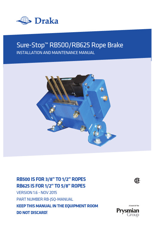
RB500 IS FOR 3/8” TO 1/2” ROPESRB625 IS FOR 1/2” TO 5/8” ROPES VERSION 1.6 - NOV 2015PART NUMBER RB-JSQ-MANUALKEEP ThIS manual In ThE EquIPmEnT ROOmDO nOT DISCaRD!ContentsDescription Page Introduction and Operational Overview 2 Certifications 2 Technical Specifications 3 Inspection 4 Packing List 4 Required Tools for Installation 4 Safety Considerations 4 Mechanical Installation 5 Electrical Installation 8 Maintenance 9 Manual Brake Release 9 Replacement Parts 9 Drawings 101Introduction and Operational OverviewThank you for purchasing the Sure-Stop™ Rope Brake from Draka. When properly installed and maintained, this product will provide years of reliable service.The patented Sure-Stop Rope Brake offers clear improvements in rope brake safety and operation:It’s a single-piece design; no separate hydraulic unit is required for operationIts compact footprint (16.3 in x 9.2 in for the RB500, 18.0 in x 9.2 in for the RB625) and height (13.2 in for the RB500 and 13.6 for the RB625) installs easily in tight spacesA simple five-wire hookup (two for power, two for controller, one for ground)eases installationCertified to CSA B44.1-04 and ASME-A17.5-2004 (cCSAus)Complies with all ASME A17.1-2007 code requirementsPlease follow the instructions throughout this manual to ensure the safety of passengers and all installation/maintenance personnel.CertificationsSure-Stop Rope Brakes are certified to CSA B44.1/ASME A17.5 and has been verified to meet all relevant ASME A17.1 code requirements. It has also been tested and certified by NETEC (National Elevator Inspection and Testing Center) report number T3-F35-09-009.Sure Stop Rope Brakes are covered under US patent 8,256,579 B2.2Technical SpecificationsRope Diameter 3/8 in to 1/2 in • 9.5 to 12.7 mm 1/2 in to 5/8 in • 12.7 to 16 mm Brake Pad Width 6 in • 152 mm 7.75 in • 197 mm Maximum Rope Spread 5.25 in • 145 mm 7.75 in • 197 mmExternal dimensions 16.25 x 8.625 x 13.2 in 18.0 x 9.125 x 13.2 in413 x 219 x 335 mm 457 x 232 x 335 mm Mounting hole dimensions 13.5 x 5.6 in • 344 x 142 mm 15.375 x 6.0 in • 391 x 152.4 mm Weight 120 lbs • 55 kg 160 lbs • 72.7 kgRotation angle up to 45 degrees up to 45 degreesMotor 120W/180W, 220VAC +/-10%, 120W/180W, 220VAC +/-10%,6A, 50/60 Hz 6A, 50/60 HzReduction rate 1:25, 1:30, 1:36 1:25, 1:30, 1:36Torque of output shaft (max) 300 kg-cm 300 kg-cm Electromagnetic brake parameter 24V, 0.5A 24V, 0.5A1:1 Roping Rated Speed 500 ft/min • 2.5 m/sec 1,200 ft/min • 6.0 m/sec1:1 Rated Load (max) 5,500 lbs • 2,500 kg 7,500 lbs • 3410 kg1:1 Rated Load (min) 440 lbs • 200 kg 1,900 lbs • 863 kg1:1 Total System Mass (max) 16,000 lbs • 7,250 kg 30,000 lbs • 13636 kg1:1 Total System Mass (min) 1,985 lbs • 900 kg 5,500 lbs • 2,500 kg2:1 Roping Rated Speed 350 ft/min • 1.75 m/sec 600 ft/min • 3 m/sec2:1 Rated Load (max) 11,000 lbs • 5,000 kg 15,000 lbs • 6818 kg2:1 Rated Load (min) 880 lbs • 400 kg 4,000 lbs • 1818 kg2:1 Total System Mass (max) 28,400 lbs • 12,900 kg 61,000 lbs • 27727 kg2:1 Total System Mass (min) 2,820 lbs • 1,280 kg 11,000 lbs • 5000 kg34Prior to installationInspectionInspect the shipping container and contents upon receipt.DO NOT install the brake if you suspect it has been damaged during shipping.Packing ListThe Sure Stop rope brake kit includes the following:RB-JSQ8 or RB-JSQ9 Sure-Stop Rope Brake - RB-JSQ8 is the RB500, RB-JSQ9 is the RB625 RB-JSQ-CABLE Power/Signal Cable RB-JSQ-MANUAL Installation ManualRequired Tools and Hardware (not included)24 mm wrench Wire strippers Flathead screwdriverMounting bolts - Four (4) M16 x 2 Class 10.9 or 5/8 in Grade 8 bolts are required for mounting the rope brake to the machine frame. Observe all recommended torque requirements:M16 x 2 Class 10.9 bolts - 310 n-m 5/8 in Grade 8 bolts - 220 ft-lbsSafety ConsiderationsEnsure that all power has been disconnected prior to installation of this device; all lockout/tag-out procedures should be observed.Observe all safety instructions contained in this manual during the installation of this product.DO NOT put your fingers between the plates -severe injury may result.Installation ConsiderationsDraka Sure Stop Rope Brakes may be mounted in any position as long as the installation requirements in the mechanical installation section are met. Wherever you choose to install the unit, make certain there is access to manually open it. There will need to be a minimum clearance of 9 in • 228 mm at the side of the unit where the power wire plugs in.5Mechanical installationPrior to installation, confirm that the structure to which the rope brakes are to be mounted can withstand the pull force generated by an event. For the RB500, the pull force is 4600 lbs - for the RB625, the pull force is 5800 lbs.Step 1Use the dimensions provided on the template on page 10 to mark the mounting hole loca-tions on the machine frame for the rope brake. It may be helpful to temporarily place the rope brake in position. Drill four mounting holes to accommodate the selected fastener.DO nOT put your fingers between the plates - severe injury may result.Pull the pointer out. Push it toward the ‘locked’ position as far as you can while keeping light pressure on it. FIRMLY turn the crank handle in the direction shown by the arrow on the motor housing.Step 3 >Loosen and remove the four (4) M16 x 1.5 nuts and washers that secure the outer (moving) plate. Remove the outer plate.unlockedlockedpointer6Step 4 >Loosen but do not remove the four (4) bolts connecting the right and left support legs to the brake assembly. This will allow you to tilt the rope brake to match the angle of the ropes as they pass through the plates.Step 5 >Place the rope brake assembly on the machine frame where you have drilled the mounting holes. Tilt the brake so that the inner (fixed) plate matches the angle of the ropes.NOTE: The ropes must be parallel to each other. If necessary, use a rope block to move the ropes.Step 6 >Using the hardware specified in the “Required Tools and Hardware” section, loosely attach therope brake to the machine frame.7Step 7 >Angle the rope brake assembly so that the inner (fixed) plate lightly touches the ropes for its entire length. (You may need to shift the position of the rope brake on the machine frame to permit full and correct contact.) Step 8Tighten the bolts that tilt the rope brake (loosened in Step 4) to a torque of 149 N-m • 110 ft-lb. Secure the rope brake assembly to the machine frame (attached in Step 6) to the torques listed on page 4.are tightened to a torque of 110 ft-lb • 149 N-m. It is typical for one pad to have slightly deeper grooves than the other. The pads and ropes should look like this. >Note: Replace the pads when the pad depth (measured from the groove crown to the back of the plate) measures 0.10 in • 2.5 mm. Pad wear varies depending on rope size, car speed, and total system mass. If the rope brakeis ever activated, inspect the pads for wear.8Electrical installationStep 1Make sure that all power has been disconnected and all circuitry locked-out.Step 2Connect the power/signal harness to the elevator controller. If 220VAC power is not available, use a 120/240VAC step-up transformer as shown in Optional Transformer Wiring below:Conductor No. Remark 1 Power 2Neutral3 and4 Securely connect wires 3 and 45 and6 Signal from controller passing through lower limit switch monitoring brake status 7GroundConnect the other end of the power/signal harness to the rope brake.Step 4 >Power up the rope brake. If the rope brake has been installed properly, the brake will be in the open position with the switch on and in the closed position with the switch off.Depending on the diameter of the hoist ropes used, the limit switch located at the bottom of the brake may require adjustment. The limit switch contacts are closed when the brake jaws are opened.To adjust the limit switch, allow the brake to close on the hoist ropes and adjust the set screw inward until the limit switch opens.9MaintenanceManual ReleaseIn certain instances, it may be necessary to open the brake manually. After confirming that the unit is powered off, follow Step 2 on page 5.Spare PartsContact Draka customer service for pricing and availability of spare parts. The toll-free number in the US and Canada is 1-877-DRAKA-EP (1-877-372-5237).WarrantyThe Sure-Stop rope brake carries a one-year warranty against defects in material and work-manship. Warranty is limited to US and Canadian customers only. A valid proof of purchase from Draka is required for any warranty claims.Failure to comply with any of the instructions or warnings outlined in this installation and maintenance manual will void all warranty claims10Rope Brake FootprintsRB500sideRB625sideFor technical assistance, call toll free (US and Canada)877.408.HELP (877.408.4357)To order kits/parts,call toll free 877.DRAKA EP (877.372.5237)R B -J S Q -M A N U A L 1115Draka Elevator2151 N. Church Street | Rocky Mount, NC 278041-877-DRAKA EP (877-372-5237)+1-252-984-5100 | Fax +1-252-972-6001Technical information 1-877-408-4357。
朗姆斯 50 60 Hz 电磁闸 产品说明书
ELECTRONICS MODULE: Solid state components epoxy encapsulated in nylon shell.
NOTES:
1. Connecteions may be made to nonenergy generating or storing hazardous location devices, such as switch contacts, noninductive resistance thermometer detectors (RTD’s) and thermocouples without necessitating a specific approval except when the device is mounted inside a tank subjected to pressure greater than 15 psi.
SPECIFICATIONS
CONTACT DESIGN: D PST: One normally open (N.O.) and one normally closed (N.C.)
CONTACT RATINGS: 8 Amperes resistive load at 250 Volts A.C. and 5 ampheres at 30 Volts D.C.
Use the following chart to determine the limits of run:
Max. Sensitivity (K OHMS) 3.3 4.7 10
住友_ESB型(多盘)电磁制动器使用说明书
’97年4月1日MA -6221 ESB 型(多盘)电磁制动器使用说明书2/15页1. 前言请检查您预定的产品是否已经送达,或是否由于在运送过程中的事故等造成破损。
如有其他不清楚的地方,请与定购点或本公司联系。
ESB型电磁制动器有许多优良的特性,但要想充分发挥其性能就需要进行正确的维修和保养。
在使用时请务必仔细阅读该使用说明书,正确使用本产品,以期长久使用。
2. 目录安全注意事项 (1)1. 前 言 (2)2. 目 录 (2)3. 构 造 (2)4. 动 作 (3)5. 主要特性 (4)6. 使用前注意事项 (4)3. 构造危险在运转时请务必设置安全罩。
由于机器是旋转的,如果胳膊或手指碰到该产品的话就会受伤。
所以为了防止危险情况的发生,避免身体的接触,请务必在设置安全罩之后再进行运转。
注意在线圈通电时制动器应处于脱开状态在确认符合您的用途或使用目的之后再安装到机器里。
‘97年4月1日 住友重机械工业株式会社7.安装注意事项......(5) 8.运转时的注意事项......(6) 9.维修和检查......(7) 10.间隙调整......(10) 11.故障及其原因和处置......(12) 12.直流电源装置 (13)MA -6221 ESB 型(多盘)电磁制动器使用说明书3/15页ESB (SB )型电磁制动器的构造如图1所示。
4. 动作该电磁制动器的动作原理如图2所示,下面依次进行说明。
首先,电磁线圈通电后,引铁就会克服弹簧压力而被磁场面吸引,内盘和外盘之间形成间隙,内盘得到释放,制动器就松开了。
切断电源后,引铁被释放,通过弹力压回原位,引铁把内盘和外盘压向定位法兰面,通过摩擦力矩,制动器就会动作。
这样,磁场在无励磁的状态下,制动器正常工作。
(一旦停电,制动器就会动作)‘97年4月1日 住友重机械工业株式会社壳体制动弹簧线圈ESB -80~250型图1图2导线安装螺栓防松螺栓 定位法兰间隙调整螺丝 内盘空心轴外盘垫圈固定螺栓壳体制动线圈 衔铁调整垫片固定螺栓 定位法兰间隙调整螺丝制动弹簧旋转轴 联轴器 内盘 外盘 安装螺栓 安装面引铁MA-6221 ESB 型(多盘)电磁制动器使用说明书5/15页在确认符合您的用途或使用目的之后再安装到机器里。
安全制动器使用
状态,首先拧松衬垫紧固螺栓,用大扳手顺时针旋转调节杆 退距缩小,反之增大,调节杆转一圈的位移量大约为2mm;
d. 拧紧衬垫紧固螺栓,关闭液压站,让制动器闭闸, 测量C值,再打开制动器,测量C尺寸的变化量; e. 反复调整,直至符合要求,将衬垫紧固螺栓拧紧。
开关功能
衬垫磨损指示
制动器开/闭指示
对应退距
制动器闭闸
制动器开闸
X mm
制动器闭闸
Y mm
制动器开闸
2mm
DD+0.5
DD+2.5
约DD+1
约DD-1
注:1)表中X对应0.5mm的衬垫磨损量时开关给出信号。
2)DD指接近开关的检测距离。
制动器使用过程中的维护
制动器是一种涉及到机构作业安全的重要部件。在使用过程中 的正确维护,对于保证制动器的正常运行、避免运行故障是十分重 要的。用户应建立相应的科学合理的维护制度。 制动器的维护制度主要有:
重超过规定值,从而导致油缸内部补偿行程S为零,这时制动弹簧力变成内力, 向外输出的制动力为零。只要将瓦块退距调整到规定值即可恢复正常。
1.护罩 2.紧固螺栓及螺母组件 3.衬垫磨损指示开关 4.开关碰板 5.安装支架 6.制动器基座 7.开闸指示开关 8.排气、测压两用接头 9.吊环螺栓 10.制动盘 11.制动衬垫 12.制动瓦 13.碟形弹簧组件 14.活塞 15.释放螺栓 16.活塞杆 17.调节杆 18. 衬垫紧固螺栓
护 帽
套
排气状态
环
不排气状态
制动器的调整
初装制动器的调整 制动器在初次安装完后使用前应进行如下检查和调整:
海尔达伯特自动手动汽车刹车和手动刹车油的保养指南说明书
Brake and Clutch FluidBrake and Clutch FluidCheck the fluid level in the reser-voirs monthly. There are up to three reservoirs, depending on model. They are:Brake fluid reservoir (all models)Clutch fluid reservoir(Manual transmission only)ABS reservoir(EX model in U.S., and optional on EX-V model in Canada)The brake fluid in the brake and Anti-lock brake systems should be replaced every 2 years or 48,000 km (30,000 miles), whichever comes first.Brake SystemThe fluid should be between the MIN and MAX marks on the side of the reservoir. If the level is at or below the MIN mark, it is anindication that your brake system needs attention. Have the brake system inspected for leaks or worn brake pads.If you add brake fluid to bring it up to the MAX mark, use Genuine Honda Brake Fluid or an equiva-lent from a sealed container that is marked DOT3 or DOT4 only.Brake fluid marked DOT5 is not compatible with your car's braking system.MaintenanceMAXMINBrake and Clutch FluidAnti-lock Brake SystemThe fluid should be between the MIN and MAX marks on the side of the reservoir. If it is at or below the MIN mark, it may indicate a problem in the braking system.Have the dealer inspect your car.If the fluid level is half an inch or more above the MAX mark, it may indicate a problem in the ABS.Have your dealer inspect the system as soon as possible.If you add brake fluid to bring it up to the MAX mark, use the same DOT3 or DOT4 brake fluid from a sealed container specified for the brake system.Clutch SystemThe fluid should be between the MIN and MAX marks on the side of the reservoir. If it is not, add brake fluid to bring it up to that level. Use the same DOT3 or DOT4brake fluid from a sealed container specified for the brake system.Low fluid level can indicate a leak in the clutch system. Have this system inspected as soon as possible.MaintenanceMAXMINPower SteeringYou should check the fluid level In the power steering reservoirmonthly. Check the level when the engine is cold. Look at the side of the reservoir. The fluid should be between the UPPER LEVEL and LOWER LEVEL. If it is below the LOWER LEVEL, add power steering fluid to the UPPER LEVEL.Using automatic transmission fluid or another brand of power steering fluid will damage the system. Use only GENUINE HONDA Power Steering Fluid-V.A low power steering fluid level can indicate a leak in the system.Check the fluid level frequently and have the system inspected as soon as possible.MaintenanceUPPER LEVELNOTICELOWERLEVELAir CleanerThe air cleaner element should be replaced every 2 years or 48,000 km (30,000 miles), whichever comes first. Under severe driving condi-tions, it should be replaced every 12months or 24,000 km (15,000 miles),whichever comes first.Follow the replacement procedure for removal and reinstallation.The air cleaner element is inside the box on the passenger's side of the engine compartment.To replace it:1. Loosen the four bolts and remove the air cleaner housing cover.2. Remove the old air cleaner element.Clean the inside of the air cleaner housing with a damp rag.3. Place the new air cleaner ele-ment in the air cleaner housing.4. Reinstall the air cleaner housing cover, tighten the four bolts.MaintenanceBOLTSAIR CLEANER ELEMENT。
电磁制动器说明书
专利号: 200410012488.6
ZD Z系 列制动电磁铁 MW Z系列制动器 安装使用说明
本产品通过国家起重运输机械质检中心检验检测 石家庄五龙制动器股份有限公司 (石家庄市制动器厂)
PDF 文件使用 "pdfFactory Pro" 试用版本创建
MYT-50-70,YTD80,
JCZ-400,ZDJ-400, MWZ2-400
MZS1-45(H)
YWZn-400,YWDZ400
MWZ3-400
MZS1-80,YTD-125
JCZ、ZDJ、YWZn 、
MWZ2-500
YWDZ-500
MWZ3-500
MZS1-100,YTD-200
JCZ、DJ、YWZn 、
本 产 品符合JB/T53459-94标准。 Z D Z 1型 的 工 作 方 式 为 : 采 用 相 对 大 电 流 强 励 磁 启 动 、 弱 电 流 励 磁 吸 持 。 Z D Z2型的工作 方式为:采用强电压励磁启动、弱电压励磁吸持并且具 有特殊设计的断电去剩磁功能。耗电少、发热低、动作非常灵敏。特别适 合于主钩等制动速度要求高、制停位置要求精确、频繁操作以及制动器需 长 时 间 开闸,短时间上闸 的场所(例如用于防风的制动器)。比MZD1、MZS1 系 列 电 磁铁节电90%以上;比仿德 液压推动器节电30%以上。 该 系 列电磁铁 除可配 本厂 生产的MWZ系列制动 架外,还可利用连接机 构 能 方 便、快捷地与TJ2、JCZ、YWZ等各种上置弹簧式制动 架相配套。
三. ZDZ系 列 单相 交 流制 动 电磁 铁 :
1.产品型号 及含义:
Z DZ
功能代号: K, 快 速 型(断 电 动 作 小 于0 .1 S) F,防风型; Y,冶金型; B,防爆型; 无字母表示普通型。
- 1、下载文档前请自行甄别文档内容的完整性,平台不提供额外的编辑、内容补充、找答案等附加服务。
- 2、"仅部分预览"的文档,不可在线预览部分如存在完整性等问题,可反馈申请退款(可完整预览的文档不适用该条件!)。
- 3、如文档侵犯您的权益,请联系客服反馈,我们会尽快为您处理(人工客服工作时间:9:00-18:30)。
ROBA-stop®-M 电磁安全制动器也有ATEX防爆设计可选, 根94/9EC(ATEX95) 防爆指示。(请与制造商联系此产品) ROBA-stop®-M 安全制动器可按客户要 求提供UL认证。
请注意 根据德国符号,小数点在本文中用逗号表 述(例如:0.5用0,5表示)。我们保留更 改尺寸和装配的权利。
IP65 密封设计,带法兰盘
(标准制动)
4 到 1600 Nm
(保持制动) 允许轴直径
8 到 90
连接转速器设计,带法兰盘
安装简述 制动器尺寸,摩擦-功率图 其它选项 制动时间,电气接线,电气附件 准则
订货号
额定扭矩,保持制动 额定扭矩标准 额定扭矩的 84 % 6) 额定扭矩的 68 % 6) 额定扭矩的 50 % 6) 额定扭矩的 34 % 6) 额定扭矩可调整 2) 6) 额定扭矩的 112 % 6) 额定扭矩的 125 % 6) 0 1 2 3 4 5 6 7 8 0 1 2 3 4 5 无附件 手动释放装置1) 摩擦盘 7) 手动释放装置/摩擦盘 1) 7) 法兰盘 8) 手动释放装置/法兰盘 1) 8)
ROBA-stop®-M 电磁安全制动器
型号 891._12.0
标准型,带摩擦盘 L3 L K1 h K2
型号 891._14.1
全封闭型(IP 65) 带法兰盘 L4 L h1 K3
型号 891._14.2
连接转速器设计 带法兰盘 L5 L2 h1
Ø D h9*
Ø G2 H8
Ø G1 H7
Ø Dg7
抱持制动器 型号 891.1_ _._
尺寸 [mm]
a b b1 c c1 c2 D D1 D2 F F1 f
规格
2 0,15 30 30 24 25 29 76 81 81 48,5 102,5 8 4 0,15 30 30 26,5 27,5 32,5 87 92 92 54 108 8 8 0,2 36 36 28,7 29,7 34,7 103 108 108 63,5 117,5 8 16 0,2 42 42 35,5 36,8 42,5 128 130 134 77 131 8 32 0,2 52 52 39,2 40,5 47,2 148 148 154 88 169 10 60 0,25 60 62 50,5 51,8 58,5 168 168 174 100,5 228,5 14 100 0,3 78 54 64 200 200 206 123 267 14 150 0,3 84 59 71 221 221 227 133 347 19 250 0,35 96 69 83 258 258 266 153 494 23 500 0,4 130 70 89 310 310 318 179 521 23 1000 0,5 180 85 106 382 382 392 -
功能
ROBA-stop®-M 是装有弹簧的电磁安全制动器
装有弹簧: 在断电状态下,螺旋弹簧(6)推压衔铁(5)。转子(3)被 固定在衔铁(5)和机器相应的固定面上。轴通过轴套 (1)被制动。 5 电磁式: 接通电源时,产生磁场。衔铁(5)克服 弹簧力被吸到铁圈铁芯(2)。制动器松 闸,转子可自由旋转。 安全制动器: 万一由于“紧急停车”或电源故障而断 电,制动器抱闸,安全且可靠。
1.2)
1000
1.2) 5)
500
3)
1000
5)
制动扭矩 输入功率 最大转速 重量
抱持制动器 1.2) 型号 891.1_ _._
800 152 1500 38 38
1600 160 1500 79 79
[rpm] 6000 [kg] [kg] 0,76 0,76
标准制动器 型号 891.0 _ _._ 抱持制动器 型号 891.1_ _._
ØM ØR Ør Ø d H7
l
245°
规格 1000 长约. 2000 mm
技术参数
标准制动器 型号 891.0 2 _ _._
1)
规格
2 Mnom Mnom Pnom nmax. [Nm] [Nm] [W] 2 4 19 4 4 8 25 5000 1,1 1,1 8 8 16 29 4000 1,8 1,8 16 16 32 38 3500 3,4 3,4 32 32 64 46 3000 4,5 4,5 60 60 100 69 3000 7,4 7,4 100 100 180 88 3000 13,6 13,6 150 150 250 98 1500 19,2 19,2 250 250 450 120 1500 33,3 33,3 500
到
1000
标准制动、金属转子3) 保持制动、金属转子r 标准制动、摩擦盘 4)
标准 11) 密封的设计 IP65 5) 转速器设计 5) 扭矩可调节 2)
举例: 16 / 891.211.0 / 24 / 16 / 6885/1
1) 规格的2-500的,不装配手动释放装置。 规格1000:仅有适用于紧急的手动释放装置。 IP65手动释放装置仅为出厂设计。. 2) 根据要求 3) 从规格60起 4) 至规格32(起重装置中制动器的操作,请联系制造商) 5) 不能与摩擦盘相配套
t Øb z
Ø b1
h9
*
Ø s1 Ø M1 Ø D1 Ø D2 Øb
c1
* 摩擦片外径: 所有规格,法兰盘外径-0.2
c2
g c2
没有的尺寸与891.011.0相同,请看第四页.
尺寸 [mm]
G G1 G2 H8 g H h h1 K K1 K2 K3 L L2 L3 L4 L5 l M M1 R r s s1 t x Z z
我们保留变更尺寸和设计的权利. 4) 轴套端面(两端)3mm深,凹面 Ø 97 5) 制动器只有超激磁才能运行 6) IP65设计配备密封罩的尺寸为1000 L = 149 mm, L4 = 170 mm. 7) 突出的螺旋塞(紧急手动释放): 8,5 mm 8) 法兰盘固定:额外的2×M12的螺栓(可要求提供尺寸)
278 325 145 115,5 253 300 161 190 6 x M10 6 x M12 8) 6 x M8 6 x M6 13 12 3-4 0 – 1,5 175 1 -
标准电压 24; 104; 180; 207 V. 依据DIN IEC 60038标准允许的电压公差 (±10 %). 1) 制动扭矩公差规格2-250=+3-%/-10%;其他调整见表3,第7页, 键规格见第3页 1.1) 最小孔径不允许制动力矩调整= 125 %. 1.2) 制动扭矩公差= +40 %/-20 % (轻微磨损是必要的) 2) 相应的最大孔径应依据第7页表2中对应的键槽及其公差选取. 3) 制动扭矩700Nm以上才能只采用过励磁制动
2
m m
孔径
标准制动器 型号 891.0 _ _._
孔径 Ø dH7 2) 2 min. max. min. max. [mm] [mm] [mm] [mm]
规格
2 8 15 8 15 4 10 15 10 15 8 11 20 11 20 32 60 100 19 22 24 30 35 45 请参考第7页,表格2 14 19 22 24 25 30 35 45 请参考第7页,表格2 16 14 25 150 30 50 30 50 250 40 1.1) 60 40 55 500 50 1.1) 80 50 75 1000 75 90 75 90
ROBA-stop -M
®
电磁安全制动器
ROB
op A-st
®
的 安全 您最 选择 刹车
.com
C
LR 108927US● 快速、低成本装配 ● 高防护等级IP54 / IP65 ● 寿命期内转子免维护
www.
K.891.V13.RC
您可靠的合作伙伴
ROBA-stop®-M 电磁安全制动器
您可信赖的制动器
其它选项,见第10页
6) 参阅第6-7页的技术说明 7) 规格 2 – 60 8) 转速器制动器的标准法兰盘 9) 只有在规格500的700Nm以上和规格1000中,才能只使用过励磁制动. 10) 不适合规格1000 11) 规格1000的标准和带编码器设计均一致;规格1000的标准(或带编码器)设 计订货号: 1000 / 891._ _ _.2 / _ / _ / _
规格
2 16,5 23,5 4 16 1 5 10 9 10 10 39 38 40 44 43 18 66 29 57 45 3 x M4 3 x M3 6 0 36 1 4 18 28,5 4 14,5 1 6 10,8 9,8 8,8 9,8 41,5 40,5 42,5 47,5 46,5 18 72 35 65 45 3 x M4 3 x M4 10 0 45 1 8 22 32,5 22 4 17,5 1 6 12,5 11,5 11,5 11,5 45,2 44,2 46,2 51,2 50,2 20 90 41 81 53 3 x M5 3 x M4 10 0 55 1 16 33 40,5 22 4 26 1,25 7 12,3 11,1 10,3 10,3 55,7 54,7 57 62,7 61,7 20 112 52 101 70 3 x M6 3 x M4 10 0 - 0,5 65 1 32 36 52,5 28 4 27 1,25 8 8,3 7,1 10,3 10,3 61,7 60,7 63 69,7 68,7 25 132 61 121 83 3 x M6 3 x M5 10 0 - 0,5 75 1 60 100 38 48 60 75,5 32 42 4 5 26 34 1,25 8 10 12 12 10,8 14 12 14 12 72,5 84 71,5 83 73,8 80,5 94 79,5 93 30 30 键的支撑长度 145 75 130,5 94 3 x M8 3 x M5 10 0-2 90 1 170 88 154 106 3 x M8 3 x M5 10 0-3 100 1 150 55 82,5 48 6 41 12 20 18 18 97 96 109 108 35 196 100 178 122 3 x M8 3 x M6 10 0-3 115 1 250 65 92 52 7 46 14 20 25,5 26 116 115 130 129 40 230 112 206 140 3 x M10 3 x M6 10 0-3 130 1 500 85 131 62 7 54,5 19 22 21,5 23 114 113 133 132 50 4) 1000 100 100 100 7 21 18,5 17,5 19 135 6) 7) 135 7) 170 6) 156 7) 70