石英晶体微天平的基本原理
石英晶体微天平电化学
石英晶体微天平电化学引言:石英晶体微天平电化学是一种基于石英晶体微天平技术的电化学研究方法,通过测量电化学反应过程中的质量变化,可以获得与电化学反应相关的信息。
本文将介绍石英晶体微天平电化学的原理、应用和发展前景。
一、石英晶体微天平的原理石英晶体微天平是一种常用的质量测量仪器,其基本原理是利用石英晶体的压电效应,将质量变化转化为频率变化。
当质量增加时,石英晶体的频率降低;当质量减少时,石英晶体的频率增加。
通过测量频率的变化,可以得到质量的变化信息。
二、石英晶体微天平电化学的原理石英晶体微天平电化学是将石英晶体微天平与电化学技术相结合,用于研究电化学反应。
在电化学反应中,电极表面的质量会发生变化,通过将电极放置在石英晶体微天平上,可以通过测量频率的变化来获得电极表面质量的变化信息。
三、石英晶体微天平电化学的应用1. 电化学催化剂研究:石英晶体微天平电化学可以用于研究电化学催化剂的活性和稳定性。
通过测量催化剂表面的质量变化,可以评估催化剂的活性和稳定性,并研究催化剂在各种条件下的性能变化。
2. 电化学腐蚀研究:石英晶体微天平电化学可以用于研究材料的电化学腐蚀行为。
通过测量材料表面的质量变化,可以评估材料的耐蚀性,并研究腐蚀过程中的质量变化规律。
3. 电化学生物传感器:石英晶体微天平电化学可以用于生物传感器的研究和开发。
通过将生物分子固定在电极表面,测量生物分子与物质相互作用引起的质量变化,可以实现对生物分子的灵敏检测。
4. 电化学药物筛选:石英晶体微天平电化学可以用于药物筛选和评价。
通过将药物固定在电极表面,测量药物与靶分子相互作用引起的质量变化,可以评估药物的活性和选择性。
四、石英晶体微天平电化学的发展前景石英晶体微天平电化学作为一种新兴的研究技术,具有广阔的应用前景。
随着纳米材料、催化剂和生物传感器等领域的发展,对于电化学反应过程的研究需求越来越高。
石英晶体微天平电化学作为一种高灵敏度、高分辨率的研究方法,将在这些领域发挥重要作用。
石英晶体微天平的基本原理和具体应用
流体通过剪切模式的声波传感器装置示意图
Liquid flow cell
70 uL flow through reservoir 1 ml static reservoir O-ring seal Resists harsh chemicals Low stress design
Static cell
x轴(电轴):沿x轴方 向或沿y轴方向施加压力 (或拉力)时,在x轴方 向产生压电效应。
y轴(机械轴):沿y轴方 向或沿x 轴方向施加压力 (或拉力)时,在y轴方 向不产生压电效应,只 产生形变。
天然右旋石英晶体晶轴的分布
石英晶体有天然的和人工培育的。 天然石英晶体产量有限,而且大部分都存 在各种缺陷。 石英晶体常见的缺陷:
ΔF = - 2 F02ΔM/A(qq)1/2
ΔF:石英晶体的频率改变量,又称频移值 (Hz);F0:石英晶体的基频;ΔM:沉积在 电极上的物质的质量改变(g);A:工作电 极的面积; q:剪切参数(2.951010 kg·m-1·s-2); q:石英的密度(2648 kg·m-3)。
可以看出,频移值ΔF与质量改变ΔM之间有一简 单的线性关系,负号表示质量升高,频率降低。
AT- 和 BT-切割模式
四、石英晶体微天平(QCM)的 工作原理
石英晶体微天平由一薄的石英圆片和覆盖其表 面的电极组成 。 外加电压加到压电材料上引起一个内在的机械 振动。因为QCM是压电的,振荡电场横着通 过装置产生一个声学波。
1. Quartz crystal 2. 2. Electrode material
QCM crystal. Grey=quartz, yellow=metallic electrodes.
一、石英晶体的结构
石英微晶天平
一、石英晶体微天平的基本原理:石英晶体微天平最基本的原理是利用了石英晶体的压电效应:石英晶体内部每个晶格在不受外力作用时呈正六边形,若在晶片的两侧施加机械压力,会使晶格的电荷中心发生偏移而极化,则在晶片相应的方向上将产生电场;反之,若在石英晶体的两个电极上加一电场,晶片就会产生机械变形,这种物理现象称为压电效应。
如果在晶片的两极上加交变电压,晶片就会产生机械振动,同时晶片的机械振动又会产生交变电场。
在一般情况下,晶片机械振动的振幅和交变电场的振幅非常微小,但当外加交变电压的频率为某一特定值时,振幅明显加大,这种现象称为压电谐振。
它其实与LC回路的谐振现象十分相似:当晶体不振动时,可把它看成一个平板电容器称为静电电容C,一般约几个PF到几十PF;当晶体振荡时,机械振动的惯性可用电感L 来等效,一般L 的值为几十mH到几百mH。
由此就构成了石英晶体微天平的振荡器,电路的振荡频率等于石英晶体振荡片的谐振频率,再通过主机将测的得谐振频率转化为电信号输出。
由于晶片本身的谐振频率基本上只与晶片的切割方式、几何形状、尺寸有关,而且可以做得精确,因此利用石英谐振器组成的振荡电路可获得很高的频率稳定度。
二、石英晶体微天平的主要构造:QCM主要由石英晶体传感器、信号检测和数据处理等部分组成。
石英晶体传感器的基本构成大致是:从一块石英晶体上沿着与石英晶体主光轴成35015'切割(AT—CUT)得到石英晶体振荡片,在它的两个对应面上涂敷银层作为电极,石英晶体夹在两片电极中间形成三明治结构。
在每个电极上各焊一根引线接到管脚上,再加上封装外壳就构成了石英晶体谐振器,其产品一般用金属外壳封装,也有用玻璃壳、陶瓷或塑料封装的。
石英晶体微天平的其他组成结构在不同型号和规格的仪器中也不尽相同,可根据测量需要选用或联用。
一般附属结构还包括振荡线路、频率计数器、计算机系统等;电化学石英晶体微天平在此基础上还包括恒电位仪、电化学池、辅助电极、参比电极等;三、石英晶体微天平的分析化学应用QCM最早应用于气相组分、有毒易爆气体的检测。
石英晶体微天平
df i dG i i h 1 h 1 i
f0
Zq
Zq 2
(4) 其他复杂情况:需能够对应力进行分析
=2nf0 n : 阶数
Zload: 加载物质的阻抗acoustic impedance
Zq : 石英晶片的阻抗
8
石英晶体微天平的可能应用
界面相互作用
胶体悬浮液粘度
2
石英晶体微天平的基本工作原理
I
载荷
石英晶:压电晶体
周期性剪切振动
U~
石英晶片
电极
基准
加载后 G df
G
14.9990 14.9995 15.0000 15.0005 15.0010
频率 [MHz]
反面
正面
有效检测表面
基准共振频率:f0 高阶共振频率:f = nf0
(n=1,3,5,7……)
频率变化:df 半峰宽变化:dG
20
40
60
80 100 120 140 160 180
Time (ms)
4
石英晶体微天平
Ring-down
trigger excitation
free decay
excitation
1/(2 G)
1/e
Voltage (Shear Amplitude)
f: modulation frequency
17
5. Adsorption kinetic 吸附过程 Formation of Lipid Bilayer
Richter et al1.8
5. Adsorption kinetic 吸附过程 Formation of Lipid Bilayer
Richter et al1.9
石英晶体微天平原理
石英晶体微天平原理石英晶体微天平(Quartz Crystal Microbalance,简称QCM)是一种利用石英晶体的振荡频率变化来测量微量物质质量的分析仪器。
其工作原理是基于石英晶体微振器在质量变化时引起谐振频率的变化。
石英晶体是一种具有垂直电极和涂有一层金属电极的薄膜石英技术器件。
在标准条件下,石英晶体具有特定的谐振频率,当质量发生变化时,石英晶体的谐振频率也会发生相应的变化。
这个质量的变化可以是溶质吸附、膜生长、能量转换等引起的。
石英晶体微天平的主要部分包括石英晶体和振荡电路。
石英晶体被放置在真空或气体环境中,通过电极与振荡电路相连。
当外加交流电场施加到石英晶体上时,晶体将发生机械振荡,并产生电荷分布,从而使晶体表面产生一定的驱动力。
这种驱动力可以通过检测电路检测出来,并转换成电信号。
石英晶体微天平利用石英晶体的材料特性和电极结构,通过测量振荡频率的变化来定量分析溶液中微量物质的吸附、反应和生长过程。
当溶液中存在微量物质时,这些物质会在石英晶体的表面上吸附或反应,并改变晶体的质量。
质量的变化将引起石英晶体的共振频率的改变,这个频率的变化与溶液中微量物质的质量变化成正比。
QCM主要分为自由振动和受控振动两种模式。
在自由振动模式下,石英晶体将自由振动,而在受控振动模式下,通过将交流电场施加到电极上,通过调节频率和振幅来控制石英晶体的振荡。
这样可以通过控制石英晶体的振荡来监测微量物质的吸附和反应过程。
石英晶体微天平在生物医学、环境监测、材料科学等领域具有广泛的应用。
例如,它可以用于研究蛋白质的吸附、细胞的生长、药物的吸附和释放等过程。
由于其高灵敏度、快速响应和无需标记的特点,石英晶体微天平已经成为一种非常重要的表征和分析技术。
总之,石英晶体微天平利用石英晶体的振荡频率变化来测量微量物质质量的分析技术。
它的工作原理是基于石英晶体在质量发生变化时引起谐振频率的变化。
通过测定谐振频率的变化,可以定量分析溶液中微量物质的吸附、反应和生长过程。
石英晶体微天平原理

石英晶体微天平原理石英晶体微天平是一种高精度的质量测量仪器,它的原理是利用石英晶体的压电效应来测量物体的质量。
石英晶体是一种具有压电效应的晶体,当施加外力时,会产生电荷,这种电荷的大小与施加的力成正比。
因此,通过测量石英晶体的电荷变化,就可以得到物体的质量。
石英晶体微天平的结构非常简单,它由一个石英晶体片和一个电极组成。
石英晶体片通常是一个长方形的薄片,厚度只有几毫米,宽度和长度分别为几毫米到几厘米不等。
电极则是两个金属片,分别固定在石英晶体片的两端。
当物体放在石英晶体片上时,物体的重力会使石英晶体片产生微小的弯曲,从而改变石英晶体片的压电效应,产生电荷。
这些电荷被电极收集起来,通过放大器放大后,就可以得到物体的质量。
石英晶体微天平的精度非常高,可以达到微克级别。
这是因为石英晶体具有非常好的稳定性和重复性,可以在长时间内保持稳定的压电效应。
此外,石英晶体的压电效应与温度、湿度等环境因素的影响非常小,因此可以在各种环境下进行精确的质量测量。
石英晶体微天平广泛应用于化学、生物、医学等领域的研究中。
例如,在化学实验中,可以用石英晶体微天平来测量化学反应中物质的质量变化,从而研究反应的动力学和热力学性质。
在生物学和医学中,石英晶体微天平可以用来测量细胞、蛋白质等生物分子的质量,从而研究它们的结构和功能。
除了石英晶体微天平,还有其他类型的微天平,如电容微天平、磁悬浮微天平等。
这些微天平的原理和应用都有所不同,但它们都具有高精度、高灵敏度的特点,可以用于各种精密测量和研究。
石英晶体微天平是一种非常重要的质量测量仪器,它的原理简单、精度高,应用广泛。
随着科技的不断发展,微天平的精度和应用范围还将不断扩大,为科学研究和工业生产带来更多的便利和发展机遇。
qcm原理
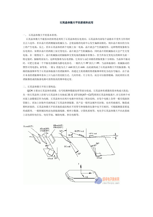
石英晶体微天平的原理和应用一、石英晶体微天平的基本原理:石英晶体微天平最基本的原理是利用了石英晶体的压电效应:石英晶体内部每个晶格在不受外力作用时呈正六边形,若在晶片的两侧施加机械压力,会使晶格的电荷中心发生偏移而极化,则在晶片相应的方向上将产生电场;反之,若在石英晶体的两个电极上加一电场,晶片就会产生机械变形,这种物理现象称为压电效应。
如果在晶片的两极上加交变电压,晶片就会产生机械振动,同时晶片的机械振动又会产生交变电场。
在一般情况下,晶片机械振动的振幅和交变电场的振幅非常微小,但当外加交变电压的频率为某一特定值时,振幅明显加大,这种现象称为压电谐振。
它其实与LC回路的谐振现象十分相似:当晶体不振动时,可把它看成一个平板电容器称为静电电容C,一般约几个PF到几十PF;当晶体振荡时,机械振动的惯性可用电感L 来等效,一般L 的值为几十mH到几百mH。
由此就构成了石英晶体微天平的振荡器,电路的振荡频率等于石英晶体振荡片的谐振频率,再通过主机将测的得谐振频率转化为电信号输出。
由于晶片本身的谐振频率基本上只与晶片的切割方式、几何形状、尺寸有关,而且可以做得精确,因此利用石英谐振器组成的振荡电路可获得很高的频率稳定度。
二、石英晶体微天平的主要构造:QCM主要由石英晶体传感器、信号检测和数据处理等部分组成。
石英晶体传感器的基本构成大致是:从一块石英晶体上沿着与石英晶体主光轴成35度15'切割(AT—CUT)得到石英晶体振荡片,在它的两个对应面上涂敷银层作为电极,石英晶体夹在两片电极中间形成三明治结构。
在每个电极上各焊一根引线接到管脚上,再加上封装外壳就构成了石英晶体谐振器,其产品一般用金属外壳封装,也有用玻璃壳、陶瓷或塑料封装的。
石英晶体微天平的其他组成结构在不同型号和规格的仪器中也不尽相同,可根据测量需要选用或联用。
一般附属结构还包括振荡线路、频率计数器、计算机系统等;电化学石英晶体微天平在此基础上还包括恒电位仪、电化学池、辅助电极、参比电极等;\三、石英晶体微天平的分析化学应用QCM最早应用于气相组分、有毒易爆气体的检测。
石英晶体微天平最基本的原理
石英晶体微天平最基本的原理石英晶体微天平最基本的原理是利用了石英晶体的压电效应:石英晶体内部每个晶格在不受外力作用时呈正六边形,若在晶片的两侧施加机械压力,会使晶格的电荷中心发生偏移而极化,则在晶片相应的方向上将产生电场;反之,若在石英晶体的两个电极上加一电场,晶片就会产生机械变形,这种物理现象称为压电效应。
如果在晶片的两极上加交变电压,晶片就会产生机械振动,同时晶片的机械振动又会产生交变电场。
在一般情况下,防腐热电偶晶片机械振动的振幅和交变电场的振幅非常微小,但当外加交变电压的频率为某一特定值时,振幅明显加大,这种现象称为压电谐振。
它其实与LC回路的谐振现象十分相似:当晶体不振动时,可把它看成一个平板电容器称为静电电容C,一般约几个PF到几十PF;当晶体振荡时,机械振动的惯性可用电感L来等效,一般L的值为几十mH到几百mH。
由此就构成了石英晶体微天平的振荡器,电路的振荡频率等于石英晶体振荡片的谐振频率,再通过主机将测的得谐振频率转化为电信号输出。
防爆热电偶由于晶片本身的谐振频率基本上只与晶片的切割方式、几何形状、尺寸有关,而且可以做得精确,因此利用石英谐振器组成的振荡电路可获得很高的频率稳定度。
二、石英晶体微天平的主要构造:QCM主要由石英晶体传感器、信号检测和数据处理等部分组成。
石英晶体传感器的基本构成大致是:从一块石英晶体上沿着与石英晶体主光轴成35015'切割(AT-CUT)得到石英晶体振荡片,铠装热电偶在它的两个对应面上涂敷银层作为电极,石英晶体夹在两片电极中间形成三明治结构。
在每个电极上各焊一根引线接到管脚上,再加上封装外壳就构成了石英晶体谐振器,其产品一般用金属外壳封装,也有用玻璃壳、陶瓷或塑料封装的。
石英晶体微天平的其他组成结构在不同型号和规格的仪器中也不尽相同,可根据测量需要选用或联用。
一般附属结构还包括振荡线路、频率计数器、计算机系统等;电化学石英晶体微天平在此基础上还包括恒电位仪、电化学池、辅助电极、参比电极等;三、石英晶体微天平的分析化学应用QCM最早应用于气相组分、有毒易爆气体的检测。
- 1、下载文档前请自行甄别文档内容的完整性,平台不提供额外的编辑、内容补充、找答案等附加服务。
- 2、"仅部分预览"的文档,不可在线预览部分如存在完整性等问题,可反馈申请退款(可完整预览的文档不适用该条件!)。
- 3、如文档侵犯您的权益,请联系客服反馈,我们会尽快为您处理(人工客服工作时间:9:00-18:30)。
Basics of a Quartz Crystal MicrobalanceIntroductionThis document provides an introduction to thequartz crystal microbalance (QCM) which is an instrument that allows a user to monitor smallmass changes on an electrode. The reader is directed to the numerous reviews1 and book chapters2 for a more in-depth description concerning the theory and application of the QCM. A basic understanding of electrical components and concepts is assumed.The two major points of this document are: •Explanation of the Piezoelectric Effect•Equivalent Circuit Models Explanation of the Piezoelectric EffectThe application of a mechanical strain to certain types of materials (mostly crystals) results in the generation of an electrical potential across that material. Conversely, the application of a potential to the same material results in a mechanical strain – a deformation. Removal of the potential allows the crystal to restore to its original orientation. The igniters on gas grills are a good example of everyday use of the piezoelectric effect. Depressing the button causes the spring-loaded hammer to strike a quartz crystal thereby producing a large potential that discharges across a gap to a metal wire igniting the gas.Quartz is by far the most widely utilized material for the development of instruments containing oscillators partly due to historical reasons (the first crystals were harvested naturally) and partly due to its commercial availability (synthetically grown nowadays). There are many ways to cut quartz crystal and each cut has a different vibrational mode upon application of a potential. The AT-cut has gained the most use in QCM applications due to its low temperature coefficient at room temperature. This meansthat small changes in temperature only result in small changes in frequency. It has a vibrational mode of thickness shear deformation as shown below in Figure 1.Figure 1. Graphical Representation of Thickness Shear Deformation.The application of an alternating potential (a sine wave in nearly all cases) to the crystal faces causes the crystal to oscillate. When the thickness of the crystal (t q) is twice the acoustical wavelength, a standing wave can be established where the inverse of the frequency of the applied potential is ½ of the period of the standing wave. This frequency is called theresonant frequency, f 0, and is given by the equationq qqt f 2/0ρμ=(1) where μq is the shear modulus (a ratio of sheer stress to shear strain), ρq is the density, and t q is the crystal thickness. The amount of energy lost during oscillation at this frequency is at a minimum. The ratio of peak energy stored to energy lost per cycle is referred to as the quality factor, Q and is given by the equationFWHMc f f Q Δ=(2)where f c is the center frequency and Δf FWHM is the full width at half max. This full width at half max is also called the bandwidth. For quartz crystals in air, Q can exceed 100,000 while in solution Q decreases to ~3000. This is because the crystal has been damped by the solution. This damping increases the amount of energy lost per cycle, decreasing Q as shown in Figure 2 below.Figure 2. Comparison of High Q and Low Q.Equivalent Circuit ModelThe mechanical model (Figure 3) of anelectroacoustical system consists of a mass (M), a compliance (C m ), and a resistance (r f ). The compliance represents energy stored duringoscillation and the resistance represents energy dissipation during oscillation.Figure 3. Quartz Crystal Microbalance Equivalent Mechanical Model.The QCM mechanical model can be electrically modeled in several different ways. The easiest model to understand might be an RLC circuit asshown in Figure 4.Figure 4. RLC Circuit.Here R 1 represents the energy dissipated during oscillation, C 1 represents the energy stored during oscillation, and L 1 represents the inertial component related to the displaced mass. At the resonant frequency, f s , the impedance of the circuit is at a minimum and is equal in magnitude to R 1 as shown in Figure 5.4.44.6 4.855.2 5.4 5.60102030FrequencyA m p l i t u d eFigure 5. Impedance Spectrum for a Series RLC Circuit.Making electrical contact to a quartz crystal is most easily done be addition of an electrode to each face of the crystal. These electrodes introduce an additional capacitance (C0) in parallel with the series RLC as shown in Figure 6. This circuit is commonly referred to as the Butterworth – van Dyke (BvD) model.Figure 6. Butterworth – van Dyke Equivalent Circuit Model.The circuit shown above now has two resonant frequencies, f s and f p, which stand for the series resonant frequency (as in the original RLC circuit) and the parallel resonant frequency, respectively. The impedance spectrum for the BvD model is shown below with a minimum at f s and a maximum at f p.Figure 7. Impedance Spectrum for the Butterworth – van Dyke Equivalent Circuit Model.Most commercial QCMs that rely upon a phaselock oscillator, manually cancel out C0, and only report the series resonant frequency, f s since f s~= f0 and f s is obviously dependent upon L1. The eQCM 10M reports both frequencies, f s and f p,and a relative impedance spectrum.Since these two resonant frequencies are dependent upon L1, mass changes on thesurface of the electrode will result in frequency changes. When a deposited film is thin andrigid, the decrease in frequency can be directly correlated to the increase in mass using the Sauerbrey4 equation.()2/122qqsmnffρμ−=Δ (3)where f0 is the fundamental frequency of the crystal as defined in Equation (1), m is the mass added, n is the harmonic number (e.g. n = 1 fora 5 MHz crystal driven at 5 MHz), and μq and ρqare as defined above. Equation (3) can be reduced tomCff−=Δ (4)where Cfis the calibration constant. The calibration constant for a 5 MHz At-cut quartz crystal in air is 56.6 Hz cm2μg-1.The majority of electrochemical experiments will correspond to a low-loading case, allowing you to directly correlate changes in frequency with changes in mass using the Sauerbrey equation (4).Once a film has been deposited and the quartz crystal is immersed in a liquid, the BvD model can be modified as shown below to include coupling to the liquid.Figure 8. Equivalent Circuit Model for a Quartz Crystal Immersed in a LiquidThree new components account for the mass loading of the film, L f , and the liquid loading (based on ηL and ρL ), L l and R l . Both new mass loadings L f and L l have the effect of reducing the frequency as indicated with the black arrow in the chart below. The original BvD model (black curve) shows resonance approximately 300 kHz higher than the modified BvD model (red curve). Notice that the shapes of the resonance curves are identical despite the addition of the film and liquid loading.1010101010105 5.2 5.45.6 5.86f / MHzZ m o d / ΩFigure 9. Comparison of BvD and Modified BvD Models.Knowing the liquid’s viscosity and density allows one to calculate 3 the expected frequency decrease upon immersing the crystal in that liquid using the equation2/12/3⎟⎟⎠⎞⎜⎜⎝⎛−=Δq q L L a f f ρπμρη (5)where f a is the frequency of the crystal in air, ηL is the viscosity of the liquid, ρL is the density of the liquid, μq is the shear modulus of the quartz crystal, and ρq is the density of the quartz crystal.For example, upon immersing the crystal in pure water, a frequency decrease of approximately 800 Hz is expected.Equation (4) holds as long as the film is assumed to be thin and rigid. When the film is no longer acoustically thin or is not rigid the BvD model can be modified further as shown below.Figure 10. One Possible Equivalent Circuit Model for a Quartz Crystal Coated with a Polymer Film and Immersed in a LiquidTwo new features have been added – Film Loading (ηf ρf ) and Elasticity (μf ). A viscoelastic polymer will influence the resonant frequencies based on the film’s viscosity (ηf ), density (ρf ) and elasticity (μf ). If the polymer is rigid or ηf ρf does not change during the experiment, there will be no change in peak shape and contributions from ηf ρf can be ignored. In cases where ηf ρf does change during the experiment, the frequency, magnitude and shape of the peak will also change as shown in Figure 11.QuartzMassLoading (film)ηf ρfμf(elasticity)ηL ρL10101010101055.25.45.65.86f / MHzZ m o d / O h m sFigure 11. Comparison of BvD and ViscousPolymer Modified BvD Models.Another way to visualize if ηf ρf is changing during an experiment is to look at the reduced quality factor, Q R as a function of time.)(2/)(s p p s R f f f f Q −+=(6)Changes in Q R correspond to changing ηf ρf . Quantifying changes in ηf ρf is challengingmathematically and will not be explored further here. The reader is directed to the literature 5 for additional information at this time.References1.Hillman, A. R. The EQCM: electrogravimetry with a light touch, J. Solid State Electrochem., 15, 2011, 1647-1660.2.Buttry, D. A. The Quartz Cystal Microbalance as an In Situ Tool for Electrochemistry, in Electrochemical Interfaces. Modern Techniques for In-Situ Interface Characterization, H. D. Abruña, Ed., VCH Publishers, Inc., New York, 1991, 531-66. Hillman, A. R. The Electrochemical Quartz Crystal Microbalance. In Instrumentation and Electroanalytical Chemistry; Bard, A. J., Stratmann, M., Unwin, P. R., Eds.;Encyclopedia of Electrochemistry; Wiley: New York, 2003; Vol. 3, 230-289.3.Glassford, A. P. M. J. Vac. Sci. Technol. 1978, 15, 1836. Kanazawa, K. K.; Gordon II, J. Anal. Chem.1985, 57, 1770. Kanazawa, K. K.; Gordon II, J. Analytica Chimica Acta 1985, 175, 99-105. 4. Sauerbrey, G. Z. Phys. 1959, 155, 206.5.Muramatsu, H.; Tamiya, E.; Karube, I. Anal. Chem. 1988, 60, 2142-2146. Hillman, A. R.; Jackson, A.; Martin, S. J. Anal. Chem. 2001, 73, 540-549. Martin; Hillman; EtchniqueBasics of A Quartz Crystal Microbalance. Rev. 1.3 12/2/2014 © Copyright 1990-2014 Gamry Instruments, Inc.。