
workbench12 模态分析培训手册
第五章
模态分析
5-1
Vibration Analysis
简介
– 假设用户已学习了第4章线性静力结构分析部分。
Training Manual
• 在这一章中,将介绍模态分析。进行模态分析类似线性静力分析。
• 本章内容:
– 模态分析步骤 – 有预应力的模态分析步骤
求解 查看结果
5-4
Vibration Analysis
…几何体和质点
• 模态分析支持各种几何体:
– 实体, 表面体 和线体
Training Manual
• 可以使用质量点:
• 质点在模态分析中只有质量(无硬度)。 • 质量点的存在会降低结构自由振动的频率。
• 材料属性: 杨氏模量,泊松比, 和 密度是必需的。
5-16
5-8
Vibration Analysis
… 求解
• 求解模型 (没有要求的结果). • 求解结束后,求解分支会显示一个图标,显示频率和模态阶数.
Training Manual
• 可以从图表或者图形中选择需要振型或者全部振型进行显示. • 嵌入“Total Deformation”结果中需要求解模态。
5-9
Vibration Analysis
… 检查结果
• 模态:
– 由于在结构上没有激励作用,因此振型只是与自由振动相关的相对值。 – 在详细列表里可以看到每个结果的频率值. – 应用图形窗口下方的时间标签的动画工具栏来查看振型
Training Manual
5-10
Vibration Analysis
• 本节所述的功能,一般适用于ANSYS DesignSpace Entra及以上版本的许 可。
5-2
Vibration Analysis
模态系统分析基础
Training Manual
• 对于模态分析,振动频率wi和模态fi 是根据下面的方程计算的出的:
• 假设:
• • • • •
K w M f 0
• 接触模态分析:
– 粗糙接触和摩擦接触:
• 将在内部表现为黏结或不分离 • 如果有间隙存在,非线性接触行为将是自由无约束的(例如, 接触不存在)
– 绑定和不分离的接触情形将取决于pinball区域的大小。
5-6
Vibration Analysis
… 分析类型
• 从Workbench的工具栏中选择“Modal”指定模型的分析类型。 • 在 Analysis Settings中:
• 模态分析与线性静态分析的过程非常相似,因此不对所有的步骤做详细介 绍。用蓝色斜体字的步骤是针对模态分析的。
– – – – – – – – – – 附加几何模型 设置材料属性 定义接触区域 (如果有的话) 定义网格控制 (可选择)
定义分析类型
加支撑 (如果有的话)
求解频率测试结果 设置频率测试选项
• 对一边固支的薄板的结构,简单对比一下两种分析
– 进行两个分析,对比模态和有预应力的模态分析的不同。
模态分析 有预应力的模态分析
Training Manual
5-14
Vibration Analysis
…没有/有预应力作用的例子
Training Manual
• 在这个例子中,提供了在有外力存在的拉伸状态下增加固有频率的方法。
2 i i
– [K] 和 [M] 不变:
假设材料特性为线弹性的 利用小位移理论,并且不包括非线性的 不存在[C] ,因此无阻尼 无{F} , 因此无激振力 结构可以强迫振动也可以不强迫振动
– 模态 {f} 是相对值,不是绝对值
5-3
Vibration Analysis
A.模态系统分析步骤
Training Manual
5-12
Vibration Analysis
…没有/有预应力作用的例子
Training Manual
• 在项目图表里建立一个静力结构分析与模态分析相结合的并有预应力存在 的分析模型。
• 注意在模型分支里,结构分析结果变成开始状态 的。
5-13
Vibration Analysis
…没有/有预应力作用的例子
模态 第一模态频率: 83.587 Hz
有预应力的模态 第一模态频率: 99.679 Hz
5-15
Vibration Analysis
D. Workshop 5.2 –预应力模态
Training Manual
• Workshop 5.2 – 预应力模态分析 • 目标:模拟拉杆在有应力和无应力状态下的模态响应(如下所示)。
– 提取的模态阶数:1到200(默认的是6)。 – 指定频率变化的范围(默认的是0到1e+08Hz)。
Training Manual
5-7
Vibration Analysis
… 载荷和约束
• 结构和热载荷无法在模态中存在。
Training Manual
• 约束:
– 假如没有或者只存在部分的约束, 刚体模态将被检测. 这些模态将处于0HZ附近. 与 静态结构分析不同, 模态分析并不要求禁止刚体运动. – 边界条件对于模态分析来说,是很重要的。因为他们能影响零件的振型和固有频率. 因此需要仔细考虑模型是如何被约束的. – 压缩约束是非线性的,因此在此分析中不被使用.
Training Manual
– 处于不变载荷作用的应力作用下的结构可能会影响固有频率,例如吉他调弦 。
K xo F
进行线性静力分析
o S
应力刚度矩阵用于计算结 构分析
K S w
2
i
M fi 0
原来的模态方程被修改为包括[S] 阵
5-5
Vibration Analysis
… 接触区域
Training Manual
• 模态分析,可能存在接触。然而,由于模态分析是纯粹的线性分析,所以,所采 用的接触不同于非线性分析中的接触类型,具体如下表所示:
Contact Type Bonded No Separation Rough Frictionless Static Analysis Bonded No Separation Rough Frictionless Initially Touching Bonded No Separation Bonded No Separation Modal Analysis Inside Pinball Region Bonded No Separation Free Free Outside Pinball Region Free Free Free Free
B. Workshop 5.1 – 模态
• Workshop 5.1 – 模态分析 • 目标:
– 检查用18号钢制造的马达盖子(如下所示)的振动特性。
பைடு நூலகம்
Training Manual
5-11
Vibration Analysis
C. 有预应力的模态
• 在某些情况下,在执行模态分析时可能需要考虑预应力影响。
ANSYS Workbench 12.1 显示动力学 中文培训教程

练习4材料的定义冲击分析中的塑性和失效Workshop Supplement 4. 材料的定义Explici Workshop Supplement冲击分析中的塑性和失效•该练习举例说明了陶瓷棒撞击下的应变率相关塑性铝板模型的定义。
而且对铝板的失效应变进行了说明超出失效应变的单元在分析中被删去随着外cit Dynam 铝板的失效应变进行了说明。
超出失效应变的单元在分析中被删去。
随着外部单元被删除,侵蚀面对面接触自动将目标面移动到下面的单元。
输入文件为barplate.inpmics wit •下面的幻灯片演示了分步操作指令。
指导教师将会做详细说明。
•barplate inp th ANSYS barplate.inp 有完整的注释。
模型主体建立完成后,/EOF 命令中止了命令流,你可以自己完成练习。
/EOF 命令后是图形用户界面产生的命令,如果你遇到任何问题,你可以与你的.LOG 文件进行对比。
YS/LS YS/LS--DYN YNA 6.0March 7, 2002Inventory #001631Workshop Supplement …Explici Workshop Supplement…冲击分析中的塑性和失效•启动ANSYS/Multiphysics/LS-DYNA 6.0图形用户界面模式cit Dynam •读入输入文件“ barplate.inp ”Utility Menu >File >Read input from >barplate inp >OKmics wit Utility Menu > File > Read input from … > barplate.inp > OK 或者运行:/input, barplate.inpth ANSYS •两部分都使用SOLID164单元YS/LS YS/LS--DYN •铝板周边固定•陶瓷棒具有向下的初始速度YNA 6.0•定义了侵彻面对面接触March 7, 2002Inventory #001631Workshop Supplement Explici Workshop Supplement…冲击分析中的塑性和失效•铝板定义为塑性随动材料模式P M t i l P M t i l M d lcit Dynam Preprocessor > Material Props > Material Models …•然后选择“Material Model Number 2” 并且,打开“LS-DYNA ”mics wit t h ANSYS th ANSYS YS/LS YS/LS--DYN •“Material Model Number 1”前面有一个文件夹标志是因为与陶瓷棒相关的材料数据(线弹性各向同性)已经输入M t i l M d lYNA 6.0关的材料数据(线弹性各向同性)已经输入。
ANSYS workbench 12.0_Introduction_DX_DOC
1
ANSYS, Inc. Proprietary
Analysis model
© 2009 ANSYS, Inc. All rights reserved.
2
ANSYS, Inc. Proprietary
Finding a good design
• In this introduction to DesignXplorer, we will use the parametric features of ANSYS Workbench to find a satisfying design for a hook. • The hook (see following slide for geometry) should : – withstand a load of 6000N – the maximum stress should not exceed the yield stress; – be robust enough so as to resist scattering of the load and unavoidable variations of its dimensions (manufacturing variations…); – And of course, its weight must be as low as possible. • To reach our goal, we will use a DOE analysis: parameters are varied continuously over given ranges and the performance of the hook is examined over these ranges. Some possible candidates for best design will be determined.
ANSYS Workbench 12.1官方中文培训教程

Workshop 3 - Results
• You can also plot contours at specific frequencies. • Click RMB on the solution object and >Insert> Stress, Strain, or Deformation
– set the scoping to all faces on the beam – set the Spatial Resolution to Use Maximum – set the Orientation to Y Axis
Training Manual
ANSYS, Inc. Proprietary © 2009 ANSYS, Inc. All rights reserved.
• The Beam (3 m x 0.5 m x 25 mm) is made of Steel.
Constrain (Fix) Both Ends
ANSYS, Inc. Proprietary © 2009 ANSYS, Inc. All rights reserved.
WS3-2
July 2009 Inventory #002666
WS3-7
July 2009 Inventory #002666
Workshop 3 - Environment
– – – – – –
Training Manual
• In the Harmonic Response branch, apply one force to one edge.
There are two edges imprinted on the beam face. Switch to Edge selection mode as necessary and >Insert>Force. Use LMB and drag over surface to highlight to pick the applicable edge. Click “Apply” in the Details window In Details, change the “Defined By” to “Components” (i.e., XYZ). Enter 250 for “Y”. Leave Phase Angle = 0
AnsysWorkbench详解教程全解
2020/1/12
12
工具条
常用工具条 图形工具条
2020/1/12
13
结构树
结构树包含几何模型的信息和整个分析 的相关过程。
一般由Geometry、Connections、Mesh、 分析类型和结果输出项组成,分析类型里包 括载荷和约束的设置。
说明分支全部被定义 说明输入的数据不完整 说明需要求解 说明被抑制,不能被求解 说明体或零件被隐藏
操作界面介绍
2020/1/12
11
菜单
常用的几个菜单项为:
—“File > Save” 用来保存数据库文件:.dsdb —“File > Clean” 用来删除数据库中的网格或结果 —“Edit > Select All” 用来选取窗口中当前的所有实体 —“Units” 用来改变单位 —“Tools >options” 用来定制或设置选项
2020/1/12
14
属性窗口
属性窗口提供了输入数据的列表, 会根据选取分支的不同自动改变。
白色区域: 显示当前输入的数据。 灰色区域: 显示信息数据,不能
被编辑。
黄色区域: 未完成的信息输入。
2020/1/12
15
图形窗口
模型和结果都将显 示在这个区域中, 包括:
Geometry Worksheet PrintPreview ReportPreview
有限元模型
有限元模型 是真实系统理想化的数学抽象。
定义
真实系统
有限元模型
节点和单元
载荷
节点: 空间中的坐标位置,具有一定自由度和 存在相互物理作用。
单元: 一组节点自由度间相互作用的数值、矩阵 描述(称为刚度或系数矩阵)。单元有线、面或实 体以及二维或三维的单元等种类。
workbench培训教程

•Welcome to the ANSYS Mechanical application introductory training course!•This training course covers the basics of using ANSYS Mechanical in performing structural and thermal analyses.•It is intended for all new or occasional ANSYS Mechanical users, regardless of the CAD software used.•Course Objectives:•General understanding of the user interface, as related to geometry import, meshing,application of loads and supports, and postprocessing•Procedure for performing FEA simulations, including linear static, modal, and harmonicstructural analyses and nonlinear steady-state thermal analyses•Utilizing parameters for ‘what-if’scenarios•Interfacing with the ANSYS solver for more advanced functionality–Training Courses are also available covering the use of other Workbench modules(e.g. DesignModeler,Design Exploration, etc.) .9:00 –10:00Lecture –Introduction10:00 –11:30Lecture –Chapter 2: Mechanical Basics11:30 –12:00Workshop 2.1 –ANSYS Mechanical Basics12:00 –1:00Lunch1:00 –1:45Lecture –Chapter 3: General Preprocessing1:45 –2:15Workshop 3.1 –Contact Control2:15 –3:15Lecture –Chapter 3: General Preprocessing (cont.) 3:15 –3:45Workshop 3.2 –Meshing Control3:45 –5:00Lecture –Chapter 4: Static Structural Analysis9:00 –9:30Workshop 4.1 –Linear Structural Analysis9:30 –10:00Lecture –Chapter 4: Static Structural Analysis 10:00 –10:30Workshop 4.2 –2D Structural Analysis10:30 –11:00Lecture –Chapter 5: Vibration Analysis11:00 –11:15Workshop 5.1 –Free Vibration Analysis11:15 –11:30Workshop 5.2 –Pre-Stressed Vibration Analysis 11:30 –12:00Lecture –Chapter 6: Thermal Analysis12:00 –1:00Lunch1:00 –1:30Workshop 6.1 –Steady State Thermal Analysis 1:30 –2:00Lecture –Chapter 7: Linear Buckling Analysis 2:00 –2:30Workshop 7.1 –Linear Buckling Analysis2:30 –3:30Lecture –Chapter 8: Results Post-processing 3:30 –4:00Workshop 8.1 –Results Processing4:00 –4:30Lecture –Chapter 9: CAD & Parameters4:30 –5:00Workshop 9.1 –Parameter Management•The Training Manual you have is an exact copy of the slides.•Workshop descriptions and instructions are included in the Workshop Supplement.•Copies of the workshop files are available on the ANSYS Customer Portal ().•Advanced training courses are available on specific topics.Schedule available on the ANSYS web page / under “Solutions> Services and Support> Training Services”.•Contents:A.About ANSYS Inc.B.ANSYS Workbench OverviewC.ANSYS Mechanical OverviewD.Starting MechanicalE.The Workbench EnvironmentF.Workbench File ManagementG.Working With UnitsH.License PreferencesANSYS, Inc.•Developer of ANSYS family of products•Global Headquarters in Canonsburg, PA -USA (south of Pittsburgh)–Development and sales offices in U.S. and around the world–Publicly traded on NASDAQ stock exchange under “ANSS”–For additional company information as well as descriptions andschedules for other training courses visit ANSYS, Inc. Family of Products include the following:•ANSYS Workbench–Complete environment for simulation andmodeling needs.•ANSYS CFD–State-of-the-art CFD solvers, including CFX and FLUENT.•ANSYS AUTODYN–Explicit dynamic solver for transientnon-linear simulations involving large deformations andstrains, non-linear material behavior, non-linear buckling,complex contact, fragmentation, and shock wavepropagation.•ANSYS LS-DYNA–LSTC’s LS-DYNA explicit dynamic solver technology with the pre-/post-processing power of ANSYS software. This powerful pairing can be used to simulate crash tests, metal forging, stamping, and catastrophic failures.•ANSYS ICEM CFD–Powerful meshing tools with generalpre-and post-processing features.•What is ANSYS Workbench?–ANSYS Workbench provides powerful methods for interacting with the ANSYS family of solvers. This environment provides a unique integration with CADsystems, and your design process.•ANSYS Workbench is comprised of various applications (some examples):–Mechanical for performing structural and thermal analyses using the ANSYS solver •Meshing is also included within the Mechanical application–Mechanical APDL for performing advanced mechanical and multiphysics analyses using the traditional ANSYS user interface.–Fluid Flow (CFX) for performing CFD analyses using CFX–Fluid Flow (FLUENT) for performing CFD analyses using FLUENT–Geometry (DesignModeler)for creating and modifying CAD geometry to prepare the solid model for use in Mechanical.–Engineering Data for defining material properties–Meshing Application for generating CFD and Explicit Dynamics meshes–Design Exploration for optimization analyses–Finite Element Modeler (FE Modeler)for translating a NASTRAN and ABAQUS mesh for use in ANSYS–BladeGen (Blade Geometry)for creating blade geometry–Explicit Dynamics for explicit dynamics simulations featuring modeling of nonlinear dynamics•The Workbench environment supports two types of applications:–Native applications (workspaces): Current native applications are Project Schematic, Engineering Data and Design Exploration.•Native applications are launched and run entirely in the Workbench window.–Data Integrated Applications: current applications include Mechanical,Mechanical APDL, Fluent, CFX, AUTODYN and others.Native ApplicationData Integrated Application•Analysis types available in Mechanical:†–Structural (static and transient):•Linear and nonlinear structural analyses.–Dynamic Capabilities:•modal, harmonic, random vibration, flexible and rigid dynamics.–Heat Transfer (steady state and transient):•Solve for temperature field and heat flux. Temperature-dependentconductivity, convection and materials allowed.–Magnetostatic:•To perform 3-D static magnetic field analysis–Shape Optimization:•Indicates areas of possible volume reduction using Topological Optimizationtechnology.†Note, the active ANSYS license dictates what functionality is available to the user. Not all features listed are covered in this Introductory course.•Mechanical Application–The environment for simulation automation and ease of use combined with the full power of the ANSYS solver technology.–Formerly called Simulation•Mechanical APDL Application–The user interface environment that emphasizes access to commands, customization and scripting.–Formerly called the ANSYS PREP7/POST1 interface•Types of licenses available for Mechanical:–Various ANSYS licensing configurations are available. The licensechosen will dictate what features and capabilities are available in theMechanical application.–License management allows license sharing when multiple instances of a particular application are open.–(Other ANSYS licenses are supported for meshing only)•Add-on licenses for Mechanical:–Rigid and Flexible Dynamics (one add-on license)–Fatigue Module•12.0 Workbench products are available for Windows and Linux operating systems.–Note, Linux will be supported starting at the 12.1 Release–Check the ANSYS web site or online documentation for the latestcompatibilities.•Network licensing capabilities are used for all ANSYS and ANSYS Workbench products.•There are two methods of launching Workbench:–From the Windows start menu:–From the CAD system•For most situations the Workbench GUI is divided into 2 primary sections (there are other optional sections we’ll see in a moment): The Toolbox The Project Schematic•The toolbox contains 4 subgroups:•Analysis systems: predefined templates that can be placed in the schematic.•Component systems: variousapplications that can be accessed to build, or expand, analysis systems.•Custom Systems: predefined analysis systems for coupled applications (FSI, thermal-stress, etc.). Users can also create their own predefined systems.•Design Exploration: Parametric management and optimization tools.•The systems and components displayed in the toolbox will depend on the installed products.•Using the check boxes in the “View All / Customize”window, the items displayed in the toolbox can be toggled on or off.•The toolbox customization window is normally left closed when not in use.•The Workbench project schematic is a graphical representation of the workflow defining a system or group of systems.•The workflow in the project schematic is always left to right.•There are currently several applications which are native to Workbench, meaning they run entirely in the Workbench window:–Project Schematic, Engineering Data and Design Exploration•Non-native applications (called data-integrated) run in their own window:–Mechanical (formerly Simulation), Mechanical APDL (formerly ANSYS),ANSYS Fluent, ANSYS CFX, Etc . . .•Blocks of cells can be deleted by RMB on the block header cell that is shaded in blue.•In this example a Static Structural analysis type is selected for the project schematic.•From the toolbox the selection can be dragged and dropped onto the schematic or simply double clicked.•By dropping applications and/or systems into various locations in the schematic, an overall analysis project is defined.•“Connectors”indicate the level of collaboration between systems.•In the example below a structural system is dragged and dropped onto a thermal system at the Model cell (A4).•Before completing the operation notice there are a number of optional “drop targets”that will provide various types of linkage between systems (continued next page).•By completing the operation from the previous page, notice the linkage here is only at the Model level and above.•In this case there would be no thermal/structural coupling.•Notice too each system block is given and alphabetic designation(A, B, C, etc.).•By dropping the structural system at the “Solution”level we obtain a structural system that is coupled to the thermal solution.”•A schematic can also be constructed by RMB and choosing to “Transfer Data To New”or “Transfer Data From New”.•In using this RMB transfer feature all transfer possibilities (upstream and downstream) are displayed.•These selections will vary depending on which cell in a particular system you highlight.•Identifying cell states:•Unfulfilled: missing upstream data.•Attention required: may need to correct this or upstream cells.•Refresh required: upstream data has changed. Need to refresh cell (update willalso refresh the cell).•Update required: the data has changed and the output of the cell must beregenerated.•Up to date.•Input changes pending: cell is locally up to date but may change when the nextupdate is performed due to upstream changes.•The “View”menu (and RMB) allows additional information to be displayed in the Workbench environment.–Below, the geometry is highlighted and the properties are displayed.•Workbench creates a project file and a series of subdirectories to manage all associated files.•Users should allow Workbench to manage the content of these directories. Please do NOT manually modify the content or structure of the project directories.•When a project is saved a project file is created (.wbpj), using the user specified file name (e.g. MyFile.wbpj).•A project directory will be created using the project name. In the above example the directory would be MyFile_files.•A number of subdirectories will be created in the project directory (explained next).•Directory Structure:–dp n: this is the design point directory. Thisessentially is the state of all parameters for aparticular analysis. In the case of a single analysisthere will be only one “dp0”directory.–global: contains subdirectories for each applicationin the analysis. In the example at right the “Mech”directory will contain the database, and otherassociated files from the Mechanical application.–SYS: the “SYS”directory will contain subdirectories for each system type in the project (e.g. Mechanical, Fluent, CFX, etc.). Each system subdirectorycontains solver specific files. For example theMECH subdirectory would contain the results file,the ds.dat file, solve.out file and so on.–user_files: contains input files, user macro files etc.that may be associated with a project.•From the Workbench “View”menu activate the“Files”option to display a window containing file details and locations.•Archive: quickly generates a singlecompressed file containing all pertinent files.–File is zip format and can be opened using the“Restore Archive . . . ”utility in WB2 or anyunzip program.–Several options are available when archivingsystems as shown here.•The Units menu in Workbench:–Allows access to predefined unit systems.–Allows the creation of custom unit systems.–Controls unit display for Engineering Data, Parameters and Charts.–Activate the Units System dialog to control.A c t i v e P r o j e c t D e f a u l t U n i t S y s t e m S u p p r e s s U n i t D i s p l ayUnits can be displayed inthe active Project system or as they were defined in their source (e.g. CAD system).•Create custom unit systems by duplicating existing systems then modifying.•Custom unit systems can be exported and imported.•Workbench license control is handled through the user interface shown below, activated from the Workbench project page (“Tools > License Preferences . . . “).•With the available licenses displayed, the activation and “use order”can be specified using the up/down arrows.–0 = off, 1 = on–License order represents the preference order for license use.•The license control allows Workbenchusers to specify whether a singlelicense is used when multipleapplications are open, or if all openapplications access their own license.•In the example shown, a user could have 3 Mechanical models open simultaneously. Using the license control they may choose to open 3 licenses or use only 1 that is shared. In the shared scenario, only the active Mechanical session uses the license (the remaining will be read only).。
ansys 12.1 workbench中文培训教程
D. Engineering Data
• The Engineering Data的应用提供了对材料属性的全面控制。
– Engineering data 是每项工程分析的必须部分。 – Engineering data 可以单独打开 (作为分析项目的开始)。
Training Manual
要打开独立的Engineering Data ,添 加工具箱中的组件系统(拖/放或双击 ),然后RMB>“编辑或双击。
Basics
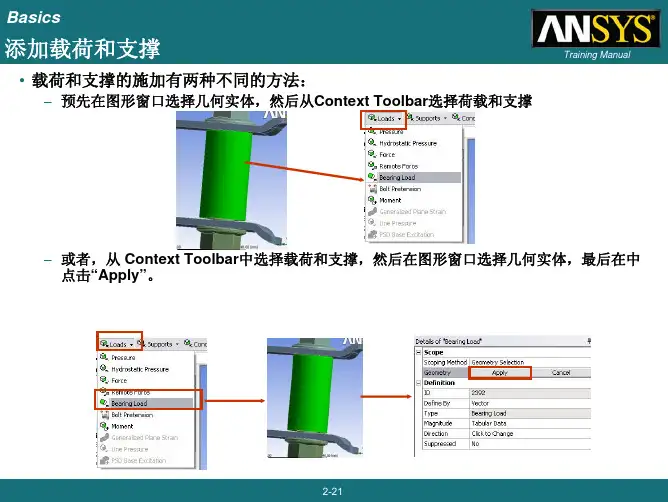
… 施加荷载和支撑
• 指定荷载类型之后,需要在Details view输入详细的数据。
– 注意, Outline Tree 下的相关载荷分支的图标将会变成完成状态。
Training Manual
2-22
Basics
… 施加载荷和支撑
• 结构载荷的施加方向:
• 若选择“Components”, 键入 X, Y, 或 Z向载荷 大小 • 若选择“Vector”, 选择确定载荷方向的几何并输 入载荷幅值 • 可以通过 “Tools > Options … > Mechanical: Miscellaneous > Load Orientation Type”改变默认选项
Training Manual
注意,添加材料到 “Favorites”列表中 ,RMB材料和添加 。
2-33
Basics
. . . Engineering Data
• 要创建新的材料首先选择材料 库的存储路径(或当前项目的 工程数据)。 • 输入一个名称,对新材料进行 说明。 • 从工具箱中双击或拖放所需的 属性。 • 最后输入属性的值。
2-36
2-31
Basics
ANSYS_Workbench12.0培训教程之模态分析
5-12
Vibration Analysis
…没有/有预应力作用的例子
Training Manual
• 在项目图表里建立一个静力结构分析与模态分析相结合的并有预应力存在 的分析模型。
• 注意在模型分支里,结构分析结果变成开始状态 的。
5-13
Vibration Analysis
…没有/有预应力作用的例子
• 接触模态分析: – 粗糙接触和摩擦接触:
• 将在内部表现为黏结或不分离 • 如果有间隙存在,非线性接触行为将是自由无约束的(例如, 接触不存在)
– 绑定和不分离的接触情形将取决于pinball区域的大小。
5-6
Vibration Analysis
… 分析类型
• 从Workbench的工具栏中选择“Modal”指定模型的分析类型。 • 在 Analysis Settings中:
5-9
Vibration Analysis
… 检查结果
• 模态:
– 由于在结构上没有激励作用,因此振型只是与自由振动相关的相对值。 – 在详细列表里可以看到每个结果的频率值. – 应用图形窗口下方的时间标签的动画工具栏来查看振型
Training Manual
5-10
Vibration Analysis
5-16
• 模态分析与线性静态分析的过程非常相似,因此不对所有的步骤做详细介绍 。用蓝色斜体字的步骤是针对模态分析的。
– – – – 附加几何模型 设置材料属性 定义接触区域 (如果有的话) 定义网格控制 (可选择)
– 定义分析类型 – 加支撑 (如果有的话) – 求解频率测试结果 – 设置频率测试选项 – 求解 – 查看结果
5-5
Vibration Analysis
Ansys-Workbench详解教程
编辑目标
用户可以对给定的目标进行复制、
粘贴、剪切等常规操作。使用Edit菜单
中的各项命令。
2021/12/31
19
第19页,共71页。
视图显示
视图的显示主要在View菜单中进行控制。 1、图形窗口
Shade Exterior and Edges:轮廓线显示
Wireframe:线框显示
对弹性区域离散化
进行单元集成, 在节点上加外载荷力
将单元内任一节点 位移通过函数表达
(位移函数)
建立单元方程
引入位移边界条件 进行求解
求解得到节点位移
根据弹性力学公式得到单元应变、应力
第7页,共71页。
有限元法的基本步骤
1. 结构离散;
2. 单元分析
a. 建立位移函数
b. 建立单元刚度方程
c. 计算等效节点力
2021/12/31
34
第34页,共71页。
网格划分
三维实体的四面体(Tetrahedron)单元 划分
三维实体的六面体(Hexahedron)单元划
分
第35页,共71页。
4 选择分析类型
静力学分析(Static Analysis) :
计算在固定不变的载荷作用下结构的响应,不考虑惯性和阻尼的影响,如 结构受随时间变化载荷的影响。
2021/12/31
2
第2页,共71页。
有限元基本概念
概念
把一个原来是连续的物体划分为有限个单元,这些单元通过有限个节点 相互连接,承受与实际载荷等效的节点载荷,并根据力的平衡条件进行分析, 然后根据变形协调条件把这些单元重新组合成能够进行综合求解的整体。
有限元法的基本思想—离散化。
安世亚太workbench入门培训手册
ANSYS Workbench - DesignModeler
• GUI布局:
– 菜单和工具条可以接受用户输入及命令 – 工具条可以根据用户要求放置在任何地方也可以自行改变其尺寸
• 两种基本的操作模式
– Sketching (2D) – Modeling (3D)
GUI – 用户图形界面
GUI 总览
Project页 也对 DesignModeler, Workbench project 或是其它一些相关文件进行管理
Project页几何体选项
• 默认选项:
– CAD实体类型导入过滤器 – 从CAD导入的参数和属性 – 指定选项和材料属性
(从ANSYS支持的CAD导入)
• 高级选项:
– CAD关联 – Reader mode save . . . (为Unigraphics
– MMB 鼠标中键
• 自由旋转 (快捷方式)
Search 搜索特定内容
Training Manual
ANSYS Workbench - DesignModeler
GUI – 用户图形界面
鼠标操作基本功能
• 基本鼠标控制 (以三键鼠标为例):
– LMB 鼠标左键
• 几何体选择 • <CTRL> +鼠标左键=添加/移除选定实体 • 按住 鼠标左键 并拖动光标 = 连续选择
ANSYS 起始页
• 启动 ANSYS Workbench后, 起始 页呈现给如下供用户选定的选项:
可以选择 “Empty Project” 建立一个 wbdb 文件.
选取Geometry图标,开始 一个新的空的 DesignModeler建模交互过 程
选择 “Workbench Projects” 按钮 搜寻一 个已存在的Projects文件
ANSYS Workbench 12.0 官方培训01-介绍
Training Manual
Lecture – Chapter 3: General Preprocessing Workshop 3.1 – Contact Control Lecture – Chapter 3: General Preprocessing (cont.) Workshop 3.2 – Meshing Control Lecture – Chapter 4: Static Structural Analysis
• What is ANSYS Workbench?
Training Manual
– ANSYS Workbench provides powerful methods for interacting with the ANSYS family of solvers. This environment provides a unique integration with CAD systems, and your design process.
• General understanding of the user interface, as related to geometry import, meshing, application of loads and supports, and postprocessing • Procedure for performing FEA simulations, including linear static, modal, and harmonic structural analyses and nonlinear steady-state thermal analyses • Utilizing parameters for ‘what-if’ scenarios • Interfacing with the ANSYS solver for more advanced functionality