NK系列真空隔离阀
闸阀和插板阀有什么区别

闸阀和插板阀有什么区别?两者优缺点?一般各用在什么地方闸阀一般用在没有颗粒的液体管道上,防止对密封面造成损坏,或在蒸汽管道上,密封效果较好。
插板阀是闸阀的一种,插板阀通常用有较大颗粒的液体管道上,或用在固体、粉体物料的管道上,一般情况下闸阀密封效果要好,插板阀密封效果差一些。
插板阀我知道的常用在有较多杂质的污水管道上,优其是环保处理管道上。
闸阀应用范围较广,根据不同的材质,应用的介质不同,闸阀具有以下优点:1、流体阻力小, 密封面受介质的忡刷和侵蚀小。
2、开闭较省力。
3、介质流向不受限制, 不扰流、不降低压力。
4、形体简单, 结构长度短,制造工艺性好,适用范围广。
缺点如下:1、密封面之间易引起冲蚀和擦伤,维修比较困难。
2、外形尺寸较大,开启需要一定的空间,开闭时间长。
3、结构较复杂。
而插板阀用于冶金,化工,能源等系统的煤气管线,是一种管道隔断设备。
闸阀跟插板阀不是一个概念插板阀很简单就是一块圆板一般是用来做阻断用的板阀是闸阀的一种。
闸阀通常用在流体管道上,而插板阀通常用在固体、粉体物料上。
闸阀的安装与维护应注意以下事项:手轮、手柄及传动机构均不允许作起吊用,并严禁碰撞。
双闸板闸阀应垂直安装(即阀杆处于垂直位置, 手轮在顶部)。
带有旁通阀的闸阀在开启前应先打开旁通阀(以平衡进出口的压差及减小开启力)。
带传动机构的闸阀,按产品使用说明书的规定安装。
如果阀门经常开关使用, 每月至少润滑一次.闸阀是作为截止介质使用,在全开时整个流通直通,此时介质运行的压力损失最小。
闸阀通常适用于不需要经常启闭,而且保持闸板全开或全闭的工况。
不适用于作为调节或节流使用。
对于高速流动的介质,闸板在局部开启状况下可以引起闸门的振动,而振动又可能损伤闸板和阀座的密封面,而节流会使闸板遭受介质的冲蚀。
从结构形式上,主要的区别是所采用的密封元件的形式。
根据密封元件的形式,常常把闸阀分成几种不同的类型,如:楔式闸阀、平行式闸阀、平行双闸板闸阀、楔式双闸板闸等。
真空阀门的几种典型结构
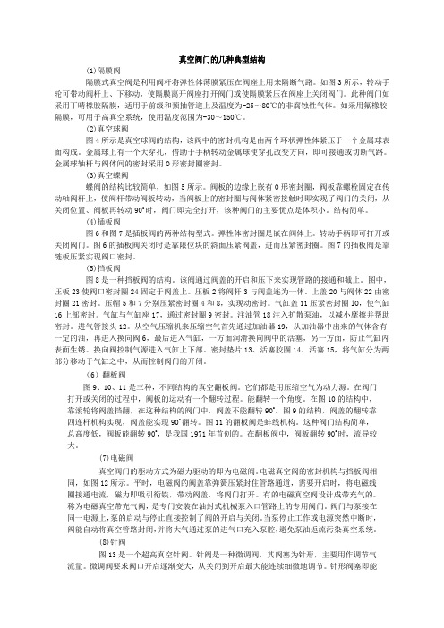
真空阀门的几种典型结构(1)隔膜阀隔膜式真空阀是利用阀杆将弹性体薄膜紧压在阀座上用来隔断气路。
如图3所示,转动手轮可带动阀杆上、下移动,使隔膜离开阀座打开阀门或使隔膜紧压在阀座上关闭阀门。
此种阀门如采用丁晴橡胶隔膜,适用于前级和预抽管道上及温度为-25~80℃的非腐蚀性气体。
如采用氟橡胶隔膜,可用于高真空系统,使用温度范围为-30~150℃。
(2)真空球阀图4所示是真空球阀的结构,该阀中的密封机构是由两个环状弹性体紧压于一个金属球表面构成。
金属球上有一个大穿孔,借助于手柄转动金属球使穿孔改变方向,即可接通或切断气路。
金属球轴杆与阀体间的密封采用O形密封圈密封。
(3)真空蝶阀蝶阀的结构比较简单,如图5所示。
阀板的边缘上嵌有O形密封圈,阀板靠螺栓固定在传动轴阀杆上,使阀杆带动阀板转动,当阀板上的密封圈与阀体紧密接触时即实现了阀门的关闭,从关闭位置、阀板再转动90O时,阀门即完全打开,该种阀门的主要优点是体积小。
结构简单。
(4)插板阀图6和图7是插板阀的两种结构型式。
弹性体密封圈是嵌在阀体上。
转动手柄即可打开或关闭阀门。
图6的插板阀关闭时是靠限位块的斜面压紧阀盖,进而压紧密封圈。
图7的插板阀是靠链板压紧实现阀口密封。
(5)挡板阀图8是一种挡板阀的结构。
该阀通过阀盖的开启和压下来实现管路的接通和截止。
图中,压板23使阀口密封圈24固定于阀盖上。
压板2将阀杆3与阀盖连为一体。
上盖20与阀体22由密封圈21密封。
压帽5和7分别压紧密封圈4和8,实现动密封。
气缸盖11压紧密封圈lO,使气缸16上部密封。
气缸与气缸座17,通过密封圈9密封。
注油管18注入扩散泵油,以减小摩擦并帮助密封。
进气管接头12。
从空气压缩机来压缩空气首先通过加油器19,从加油器中出来的气体含有一定的油,再进入换向阀6,最后进入气缸,一方面润滑换向阀中的活塞,另一方面,防止气缸内表面生锈。
换向阀控制气源进入气缸上下部。
密封垫片13、活塞胶圈14、活塞15,将气缸分为两部分移动于气缸之中,从而控制阀门的开闭。
主蒸汽、抽气系统
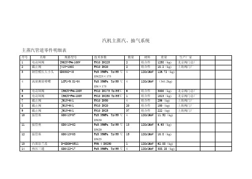
汽机主蒸汽、抽气系统主蒸汽管道零件明细表序号名称规格型号技术参数数量材料重量生产厂家1 电动闸阀Z962Y-P W54100V PN10 DN2252 组合件1258(kg)北京阀门总厂2 截止阀J41Y-100I PN10 DN20 2 组合件18.2(kg)上海阀门厂4 12Cr1MoV 126.72(kg)3 钢管模压大小头GD0302-40 P=5.39MPa T=495℃DN225×1754 流量测量喷嘴LCP1-9.81-04 P=5.39MPa T=495℃4 12Cr1MoV (361.2kg)DN×1755 电动闸阀Z962Y-P W54100V PN10 DN175 T=495℃6 组合件3000(kg)北京阀门总厂6 电动闸阀Z962Y-P W54100V PN10 DN250 T=495℃ 1 组合件1013(kg)北京阀门总厂7 截止阀J61Y-641 PN10 DN50 4 组合件256(kg)上海阀门厂8 截止阀J61Y-641 PN10 DN20 20 组合件100(kg)上海阀门厂9 截止阀J61Y-641 PN10 DN25 37 组合件222(kg)上海阀门厂4 12Cr1MoV 11.52(kg)10 接管座GD0413-07 P=5.39MPa T=495℃DN5013 12Cr1MoV 6.63(kg)11 接管座GD0413-02 P=5.39MPa T=495℃DN2012 接管座GD0413-03 P=5.39MPa T=495℃15 12Cr1MoV 10.8(kg)DN2513 凸面法兰盖D-GD86-0511 PN6.4 DN250 1 12Cr1MoV 62.88(kg)14 热压三通GD0422-17 P=5.39MPa T=495℃ 4 12Cr1MoV 388.28(kg)DN250×17515 电动闸阀Z941Y-641 PN6.4DN250T=495℃ 1 组合件595(kg)北京阀门总厂1 12Cr1MoV 18.77(kg)16 焊接堵头GD0612-15 P=5.39MPa T=495℃DN2501 12Cr1MoV 71.04(kg)17 热压三通GD0422-17 P=5.39MPa T=495℃DN250×15018 多级节流孔板D-GD87-901-2/69 PN<10 DN25 6 12Cr1MoV 1.788(kg)19 漏斗D-GD87-911-1/8 DN25 11 1.771(kg)20 组合件 1.771(kg)20 蠕胀测点D-GD87-0908-1/7~2/721 电动闸阀Z941Y-614 PN6.4DN150T=495℃ 1 组合件301(kg)北京阀门总厂22 凸面法兰盖D-GD86-0511 PN6.4 DN150 1 12Cr1MoV 26.32(kg)φ194 1 12Cr1MoV 5.159(kg)23 三向位移指示器D-GD87-0905-1/18~18/1824 三向位移指示器D-GD87-0905-1/18~φ273 1 12Cr1MoV 5.159(kg)18/1825 对焊凸法兰GD0502 PN6.4 DN150 1 12Cr1MoV 26.11(kg)26 对焊凸法兰GD0502 PN6.4 DN250 1 12Cr1MoV 54.61(kg)4 12Cr1MoV 380.2(kg)27 90o热压弯头P=5.39MPa T=495℃DN25022 12Cr1MoV 778.58(kg)28 90o热压弯头P=5.39MPa T=495℃DN1502 12Cr1MoV 41.02(kg)29 45o热压弯头P=5.39MPa T=495℃DN1504 12Cr1MoV 12.4(kg)30 90o热压弯头P=5.39MPa T=495℃DN5031 无缝钢管GB5310-85 φ273×204,48m 12Cr1MoV 559.02(kg)32 无缝钢管GB5310-85 φ273×1168.8m 12Cr1MoV 4292.3(kg)33 无缝钢管GB5310-85 φ194×8164.5m 12Cr1MoV 6037.2(kg)34 无缝钢管GB5310-85 φ76×610m 12Cr1MoV 103.6(kg)35 无缝钢管GB5310-85 φ38×3.0200m 12Cr1MoV 518(kg)36 无缝钢管GB5310-85 φ28×2.580m 12Cr1MoV 125.6(kg)GB3092-82 Φ42.3×3.2580m Q215A 250.4(kg)37 低压流体输送钢管56套2950(kg)38 主蒸汽管道支吊架一段抽气管道明细表序号名称规格型号技术参数数量材料重量生产厂家1 电动闸阀Z962Y-P W54100V PN16 DN4502 组合件1258(kg)北京阀门总厂2 90o热压弯头GB387-82 PN16 DN450 6 20 600(kg)3 手动闸阀 Z41H-25C PN16 DN450 1 200(kg)4 法兰JB/T81-1994PN16 DN4506Q235A120(kg)5 无缝钢管GB5310-85Φ473×20 30m203726(kg)8套604(kg)6 一段抽气管道支吊架二段抽气管道明细表序号名称规格型号技术参数数量材料重量1 截止阀J41H-25 PN2.5 DN100 1 34.5(kg)2 平焊钢法兰JB/T81-1994 PN2.5 DN1003 Q235A 18(kg)3 无缝钢管GB/T8163-1999 Φ89×4×10000 1 20 419(kg)4 无缝钢管GB/T8163-1999 Φ108×4×20000 1 20 305(kg)5 无缝钢管GB/T8163-1999 Φ133×4×10000 1 20 127.5(kg)6 无缝钢管GB/T8163-1999 Φ159×4×5000 1 20 88.5(kg)7 无缝钢管GB/T8163-1999 Φ273×4×5000 1 20 261.5(kg)8 无缝钢管GB/T8163-1999 Φ18×3×8000 1 20 8.88(kg)9 无缝钢管GB/T8163-1999 Φ22×2×6000 1 20 5.9(kg)10 无缝钢管GB/T8163-1999 Φ45×3.5×30000 1 20 107.4(kg)11 无缝钢管GB/T8163-1999 Φ57×3.5×20000 1 20 68.8(kg)12 截止阀J41H-160 PN16 DN25 1 10.7(kg)13 平焊钢法兰JB/T82.2-1994 PN16 DN25A型 1 20-1 3.16(kg)14 平焊钢法兰JB/T82.2-1994 PN16 DN25B型 1 20-1 2.97(kg)15 截止阀J41H-100 PN10 DN25 1 14(kg)16 平焊钢法兰JB/T82.2-1994 PN16 DN25A型 1 20-1 2.86(kg)17 平焊钢法兰JB/T82.2-1994 PN16 DN25B型 1 20-1 2.67(kg)18 截止阀J41-40 PN4.0 DN25 1 8.7(kg)19 平焊钢法兰JB/T82.2-1994 PN4 DN25A型 2 20-1 2.62(kg)20 滤汽器SQ01.63.05-1 1 9(kg)21 无缝钢管GB/T8163-1999 Φ32×3.5×15000 1 20 37(kg)41套1476.7(kg) 22 汽机本体轴封管道支吊架三段抽气管道零件明细表序号名称规格型号技术参数数量材料重量生产厂家1 气动止回阀H644-25C PN2.5 DN250 1 294(kg)2 对焊平法兰GD0505 PN2.5 DN250 2 20 47.36(kg)3 真空隔离闸板阀NKZ64H-16C PN1.6 DN250 1 326(kg)4 焊接堵头GD0614-15 PN4 DN250 1 20 9.33(kg)5 90o热压弯头GB387-82 PN4.0 DN250 7 20 215.53(kg)6 无缝钢管GB3087-82 Φ219×6 3.26m 20 102.76(kg)7 无缝钢管GB3087-82 Φ273×78.177m 20 375.49(kg)8 真空隔离截止阀NKJ61H-16C PN1.6 DN20 6 42(kg)9 疏水器GD0616-15 PN1.6 DN200 2 Q235A 8.46(kg)11 漏斗D-GD87-907-1/8 Φ32 3 Q215A 0.948(kg)12 无缝钢管GB3087-82 Φ32×2.510m 20 18.2(kg)13 无缝钢管GB3087-82 Φ25×220m 20 22.6(kg)14 低压流体输送钢GB3092-82 Φ33.5×3.2510m Q215A 24.2(kg)管15 10套199(kg)低压蒸汽及工业供汽管道零件明细表序号名称规格型号技术参数数量材料重量生产厂家1 电动闸阀 Z941H-25C PN2.5 DN4002 2054(kg)北京阀门总厂2 对焊平法兰GD0505 PN2.5 DN400 6 20 397.38(kg)3 闸阀 Z41H-25C PN2.5 DN250 1 207(kg)4 对焊平法兰GD0505 PN2.5 DN2506 20 47.360(kg)5 电动闸阀 Z941H-25C PN2.5 DN125 4 616(kg)北京阀门总厂6 闸阀 Z41H-25C PN2.5 DN125 2 232(kg)7 对焊平法兰GD0505 PN2.5 DN125 12 20 115.56(kg)8 气动止回阀H644H-25C PN2.5 DN100 2 529(kg)9 闸阀 Z41H-25C PN2.5 DN100 9 621(kg)10 对焊平法兰GD0505 PN2.5 DN100 24 20 168.48(kg)11 电动调节阀PN4.0 2 700(kg)12 减压阀Y45H-25C PN2.5 DN100/DN80 2 432(kg)13 对焊平法兰GD0505 PN2.5 DN80 6 Q235A 30.18(kg)14 闸阀 Z41H-25C PN2.5 DN80 2 100(kg)15 闸阀 Z41H-25C PN2.5 DN50 2 68(kg)16 对焊平法兰GD0505 PN2.5 DN50 4 20 11.64(kg)17 闸阀 Z41H-25C PN2.5 DN400 1 900(kg)18 钢板焊制大小头 GD0309-48 PN2.5 DN400×300 2 20 39.04(kg)19 钢板焊制大小头 GD0309-47 PN2.5 DN400×250 1 20 27.2(kg)20 钢板焊制大小头 GD0309-23 PN2.5 DN200×125 2 20 8.44(kg)21 钢板焊制大小头 GD0309-22 PN2.5 DN200×100 4 20 19.56(kg)22 钢板焊制大小头 GD0309-15 PN2.5 DN125×100 1 20 0.69(kg)23 钢板焊制大小头 GD0309-08 PN2.5 DN80×50 2 20 1.02(kg)GD0742-13 PN2.5 DN400 2 712(kg)24 流量测量孔板对焊法兰组件25 电动截止阀 J91H-16C PN1.6 DN50 2 120(kg)26 90o热压弯头GB0219-73 PN4 DN400 7 20 807(kg)27 60o热压弯头GB0219-53 PN4 DN400 2 20 153.88(kg)28 30o热压弯头GB0219-13 PN4 DN400 2 20 76.94(kg)29 90o热压弯头GB0219-71 PN4 DN300 6 20 297.54(kg)30 90o热压弯头GB0219-70 PN4 DN250 2 20 71.58(kg)31 90o热压弯头GB0219-65 PN4 DN125 25 20 94.75(kg)32 30o热压弯头GD0219-05 PN4 DN125 2 20 2.52(kg)33 90o热压弯头GB0219-64 PN4 DN100 43 20 104.06(kg)34 60o热压弯头GD0219-44 PN4 DN100 2 20 3.22(kg)35 45o热压弯头GD0219-24 PN4 DN100 7 20 8.47(kg)36 30o热压弯头GD0219-04 PN4 DN100 2 20 1.62(kg)37 90o热压弯头GB0219-64 PN4 DN80 10 20 15.8(kg)38 90o热压弯头GB0219-61 PN4 DN400 4 20 1.88(kg)39 无缝钢管GB3087-82 Φ425×1180.53m 20 6754(kg)40 无缝钢管GB3087-82 Φ325×8 2.72m 20 733.59(kg)41 无缝钢管GB3087-82 Φ273×711.73m 20 124.9(kg)42 无缝钢管GB3087-82 Φ133×460m 20 1025.15(kg)43 无缝钢管GB3087-82 Φ108×4153.49m 20 1574(kg)44 无缝钢管GB3087-82 Φ89×427m 20 226.26(kg)45 无缝钢管GB3087-82 Φ57×36m 20 24(kg)46 圆钢Φ175m Q235A 8.9(kg)47 圆钢Φ612m Q235A 2.664(kg)48 截止阀J42H-25C PN2.5 DN20 29 203(kg)上海阀门厂49 截止阀J42H-25C PN2.5 DN25 12 88.8(kg)上海阀门厂50 截止阀J42H-25C PN2.5 DN32 14 196(kg)上海阀门厂51 疏水器PN2.5 DN25 4 14.8(kg)52 对焊平法兰GD0505 PN2.5 DN32 28 20 53.76(kg)53 对焊平法兰GD0505 PN2.5 DN25 24 20 27.36(kg)54 对焊平法兰GD0505 PN2.5 DN20 58 20 58(kg)55 漏斗D-GD87-907-2/8-4/8 Φ4810 Q215A 5.25(kg)56 漏斗D-GD87-907-2/8-4/8 Φ33.529 Q215A 15.225(kg)57 无缝钢管GB3087-82 Φ32×2.590m 20 101.7(kg)58 无缝钢管GB3087-82 Φ38×2.515m 20 27.3(kg)59 无缝钢管GB3087-82 Φ25×240m 20 87.6(kg)GB3092-82 Φ33.5×450m Q215A 145.5(kg) 60 低压流体输送焊接钢管61 低压流体输送焊GB3092-82 Φ48×2.520m Q215A 76.8(kg)接钢管62 道支吊架90套4407(kg)工业抽汽安全阀排气管道零件明细表序号名称规格型号技术参数数量材料重量1 无缝钢管GB3087-82 Φ25×210m 20 11.3(kg)2 无缝钢管GB3087-82 Φ32×2.52m 20 3.64(kg)3 无缝钢管GB3087-82 Φ325×81m 20 62.54(kg)4 无缝钢管GB3087-82 Φ426×1119m 20 2138.8(kg)5 90o热压弯头GB0219-71 PN4.0 DN300 2 20 99.81(kg)6 90o热压弯头GB0219-73 PN4.0 DN400 5 20 577(kg)7 截止阀 J41H-16C PN1.6 DN32 2 组件23.2(kg)8 对焊平法兰GD0505 PN1.6 DN32 4 20 7.52(kg)9 无缝钢管GB3087-82 Φ38×2.520m 20 43.8(kg)GB3092-82 Φ48×42520m Q215A 91.6(kg) 10 低压流体输送钢管11 漏斗D-GD87-907-1/8 Φ25 2 Q215A 0.64(kg)12 支吊架6套417(kg)除氧器汽平衡及连排二次蒸汽管道零件明细表序号名称规格型号技术参数数量材料重量1 闸阀 Z41T-16C PN1.6 DN100 3 189(kg)2 平焊法兰GD0507 PN1.6 DN100 6 Q235A 25.38(kg)3 闸阀 Z41T-16C PN1.6 DN504 116(kg)4 平焊法兰GD0507 PN1.6 DN50 8 Q235A 20(kg)5 钢板焊制大小头GB0309-17 PN1.6 DN150X100 1 Q235A-F 1.72(kg)6 平焊法兰GD0507 PN1.6 DN150 6 Q235A 42.48(kg)7 泵入口滤网PN1.6 DN100 3 20 135(kg)8 钢板焊制大小头GB0309-17 PN1.6 DN200 2 Q235A 5.16(kg)9 90o热压弯头GB0219-61 PN4.0 DN50 30 20 14.1(kg)10 90o热压弯头GB0219-64 PN4.0 DN100 9 20 21.78(kg)11 无缝钢管GB3087-82 Φ57×350m 20 200(kg)12 无缝钢管GB3087-82 Φ108×456m 20 574.56(kg)13 90o热压弯头GB0219-64 PN4.0 DN100 16 20 38.72(kg)14 45o热压弯头GB0219-26 PN4.0 DN150 1 20 3.04(kg)15 90o热压弯头GB0219-66 PN4.0 DN150 13 20 78.65(kg)16 90o热压弯头GB0219-68 PN4.0 DN200 8 20 118.8(kg)17 截止阀 J41H-16C PN1.6 DN20 6 43.8(kg)18 平焊法兰GD0507 PN1.6 DN20 8 Q235A 6.88(kg)19 无缝钢管GB3087-82 Φ25×230m 20 33.9(kg)GB3092-82 Φ33.5×3.2510m Q215A 24.2(kg) 20 低压流体输送钢管21 漏斗D-GD87-907-1/8 Φ33.5 5 Q215A 1.58(kg)22 管道支吊架13套247(kg)除氧器安全阀排气及除氧器排气管道明细表序号名称规格型号技术参数数量材料重量1 截止阀 J41H-16C PN1.6 DN502 组件38(kg)2 对焊平法兰GD0505 PN1.6 DN50 4 20 11.56(kg)3 无缝钢管GB3087-82 Φ57×360m 20 240(kg)4 90o热压弯头GB0219-61 PN4.0 DN50 12 20 5.64(kg)5 对焊平法兰GD0505 PN1.6 DN20 12 20 11.76(kg)6 无缝钢管GB3087-82 Φ25×250m 20 56.5(kg)7 低压流体输送钢GB3092-82 Φ33.5×450m Q215A 145.5(kg)管8 漏斗D-GD87-907-1/8 Φ25 6 Q215A 1.92(kg)9 45o热压弯头GD0219-25 PN4.0 DN125 1 20 1.99(kg)10 90o热压弯头GB0219-65 PN4.0 DN125 16 20 63.84(kg)11 无缝钢管GB0119-01 PN2.5Φ65×3.5150m 20 939(kg)12 无缝钢管GB0119-01 PN2.5Φ133×480-m 20 1018.4(kg)13 支吊架1套378.5(kg)。
几款真空阀简介及运用
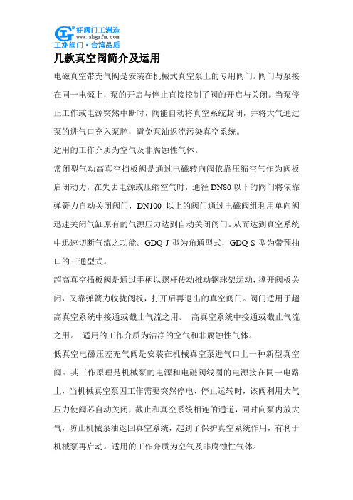
几款真空阀简介及运用电磁真空带充气阀是安装在机械式真空泵上的专用阀门。
阀门与泵接在同一电源上,泵的开启与停止直接控制了阀的开启与关闭。
当泵停止工作或电源突然中断时,阀能自动将真空系统封闭,并将大气通过泵的进气口充入泵腔,避免泵油返流污染真空系统。
适用的工作介质为空气及非腐蚀性气体。
常闭型气动高真空挡板阀是通过电磁转向阀依靠压缩空气作为阀板启闭动力,在失去电源或压缩空气时,通径DN80以下的阀门将依靠弹簧力自动关闭阀门,DN100以上的阀门通过电磁阀组利用单向阀迅速关闭气缸原有的气源压力达到自动关闭阀门。
从而达到真空系统中迅速切断气流之功能。
GDQ-J型为角通型式,GDQ-S型为带预抽口的三通型式。
超高真空插板阀是通过手柄以螺杆传动推动钢球架运动,撑开阀板关闭,又靠弹簧力收拢阀板,打开后再退出的真空阀门。
阀门适用于超高真空系统中接通或截止气流之用。
高真空系统中接通或截止气流之用。
适用的工作介质为洁净的空气和非腐蚀性气体。
低真空电磁压差充气阀是安装在机械真空泵进气口上一种新型真空阀。
其工作原理是机械泵的电源和电磁阀线圈的电源接在同一电路上,当机械真空泵因工作需要突然停电、停止运转时,该阀利用大气压力使阀芯自动关闭,截止和真空系统相连的通道,同时向泵内放大气,防止机械泵油返回真空系统,起到了保护真空系统作用,有利于机械泵再启动。
适用的工作介质为空气及非腐蚀性气体。
电磁高真空充气阀是以电磁力为动力,当接通电源时,阀门被关闭,使真空系统与大气隔离;切断电源时,阀门处于开启状态,随之大气由外界引入真空系统。
GQC-4A型电磁高真空充气阀具有通电开启和通电关闭两种功能,阀内带有空气过滤器,可用作向真空系统充气。
阀门适用的介质为空气及非腐蚀性气体。
电磁高真空挡板阀是靠电磁力和弹簧复位力,用以打开或关闭的阀门,适用于真空系统中用以打开或隔断气流之用。
当阀关闭时,允许阀板密封面上侧承受大气压,下侧为真空,在此状态下接通电器控制盒电源后,阀板能正常开启。
NKZ41H真空隔离闸阀

首页>>产品中心>>NKZ41H真空隔离闸阀一、主要性能规范 Chief property and specification :试验压力 Test pressure二、使用范围 Applicable :三、主要零件材料 Materials for main parts :四、主要尺寸及重量 Main dimensions and weight:五、主要尺寸及重量 Main dimensions and weight:订货须知:一、①NKZ41H真空隔离闸阀产品名称与型号②NKZ41H真空隔离闸阀口径③NKZ41H真空隔离闸阀是否带附件二、若已经由设计单位选定公司的NKZ41H真空隔离闸阀型号,请按NKZ41H真空隔离闸阀型号三、当使用的场合非常重要或环境比较复杂时,请您尽量提供设计图纸和详细参数,相关产品:电动真空球阀GI高真空蝶阀GDQ-J气动高真空挡板阀真空球阀气动真空球阀气动真空球阀<<阀门采购流程及注意事项>>:1、询价应当找专业符合阀门产品的厂家,尽量找有实力的品牌或合作过的厂家,避免技术不成熟、价格昂贵、质量不过关、货期时间长。
2、提供准确详细的产品询价内容,最好提供设计院的图纸或相关资料。
3、寻找两到三家企业报价最为对比,并了解是否符合产品相关要求。
4、跟厂家确认质量达标问题、增值税发票问题、运费问题、包装方式问题、货期问题。
5、将准确的询价单及图纸提交给专业技术人员进行确认。
6、采购前先检查供应商的资质、产品检验报告、相关案例等。
7、下单时检查合同内的事项是否有跟变及是否符合要求,避免照成后续一些不必要的问题出现。
8、收到阀门后注意检查是否有合格书、标牌、质保书、检验报告、保修卡、产品说明书。
9、检查产品在适合在运输过程中照成损坏,是否有明显的质量问题。
<<阀门的分类>>阀门的用途广泛,种类繁多,分类方法也比较多。
上海电立阀门厂电站阀门系列

上海电立阀门厂电站阀门系列名称:电站阀门(核级阀门)型号:J(L)61Y/J(L)62Y/HL6-HZ1X(Y)/Z61Y/Z62Y材质:WCB/CF3/304/316L等工作温度:425~900ºC简介:“电站阀门”也称电站专用阀门/核级阀门,主要适用于火力电站各种系统的管路上,切断或接通管路介质。
适用介质:水、蒸气等非腐蚀性介质。
电站阀门与其他阀门产品相比的特点是高温高压,独特的自密封设计,压力越高,密封越可靠。
由于性能技术特性、工况的特殊使产品也形成了其他产品所替代不了的特点。
设计与制造GB/T12234 ASMEB16.34结构长度JB/T3595/ 接口连接尺寸JB/T3595 GB/T12224 /检验与试验JB/T3595 MSS SP61压力与温度基准JB/T3595 ANSI B16.34 。
主要压力等级:公称压力PN1.0~PN150 工作压力P 55 100V、P 55 140V、P 55 170V 。
电站阀结构优势:1.采用压力自紧式密封,阀体支管两端为焊接连接。
2.阀座、阀瓣密封面采用钴基硬质合金堆焊或等离子喷焊而成,耐高温,耐磨、抗擦伤性能好。
3.阀杆经抗腐蚀性氮化处理,有良好的抗腐蚀性和抗擦伤性。
电站阀基本分类:电站闸阀,电站截止阀,电站止回阀,高温高压电站阀门上海电立阀门厂闸阀系列名称:闸阀型号:Z41H(T/W)/Z44H(T/W)/Z11H(T/W)/Z43HF/Z641H/Z941H材质:WCB/CF3/304/316L/灰铸铁等工作温度:-29~500ºC简介:闸阀—上海电立阀门系列产品:高压闸阀。
高温闸阀。
高压高温闸阀。
电动闸阀Z941H。
气动闸阀Z641H。
保温闸阀BZ41H。
高温高压闸阀Z41Y/Z61Y。
两项流闸阀LXLZ971/3H。
高温灰渣闸阀。
带吹扫孔闸阀。
衬氟闸阀Z41F。
正齿轮闸阀Z442Y、伞齿轮闸阀Z542H。
平板闸阀、带导流孔闸阀ZF23Y/ZF83Y/ZF43Y/ZF63Y。
LVMK-SMY25EN 直 operated 2 3 隔离阀门 LVMK 系列说明书

Instruction ManualDirect operated 2/3 Port Isolated valveLVMK SeriesThe intended use of is for the control of the downstream fluid supply.1 Safety InstructionsThese safety instructions are intended to prevent hazardous situationsand/or equipment damage. These instructions indicate the level ofpotential hazard with the labels of “Caution,” “Warning” or “Danger.”They are all important notes for safety and must be followed in additionto International Standards (ISO/IEC) *1), and other safety regulations.*1) ISO 4414: Pneumatic fluid power - General rules relating to systems.ISO 4413: Hydraulic fluid power - General rules relating to systems.IEC 60204-1: Safety of machinery - Electrical equipment of machines.(Part 1: General requirements)ISO 10218-1: Manipulating industrial robots -Safety. etc.•Refer to product catalogue, Operation Manual and HandlingPrecautions for SMC Products for additional information.• Keep this manual in a safe place for future reference.Caution Caution indicates a hazard with a low level of risk which, ifnot avoided, could result in minor or moderate injury.Warning Warning indicates a hazard with a medium level of riskwhich, if not avoided, could result in death or serious injury.Danger Danger indicates a hazard with a high level of risk which, ifnot avoided, will result in death or serious injury.Warning•Always ensure compliance with relevant safety laws andstandards.•All work must be carried out in a safe manner by a qualified person incompliance with applicable national regulations.2 SpecificationsModelBody ported (Tubing type) Base mountedLVMK21 LVMK27 LVMK23Valve type N.C.Number of ports 2Fluid 1)Air, Water, Deionized water, Diluent,Cleaning fluidOperating pressure range −90 kPa to 0.2 MPaOrifice diameter 2 mm equivalentResponse time 2)16 ms or less (air)Internal / External Leakage Zero leakage (at water pressure)Proof pressure 3)0.3 MPaAmbient Temperature 5 to 50°C (No condensation)Fluid Temperature 5 to 50°CMounting orientation 4)FreeEnclosure IP40Weight 5)76g 77g 76gTable 12 Specification – continuedModelBody ported (Tubing type) Base mountedLVMK202 LVMK207 LVMK205Valve type UniversalNumber of ports 3Fluid 1)Air, Water, Deionized water, Diluent,Cleaning fluidOperating pressure range −90 kPa to 0.2 MPaOrifice diameter 2 mm equivalentResponse time 2) 16 ms or less (air)Internal / External Leakage Zero leakage (at water pressure)Proof pressure 3) 0.3 MPaAmbient Temp. 5 to 50°C (No condensation)Fluid Temperature 5 to 50°CMounting orientation 4) FreeEnclosure IP40Weight 5) 78g 78g 79gRated Voltage 12, 24 VDCVoltage fluctuation 6) ±10% of rated voltageType of coil insulation Class BPower Consumption(When rated voltage is 24V)3 W(0.125 A)Coil switching noise 7) 70 dB (A)Table 3Notes:1) Be sure to confirm the fluid compatibility in advance.2) Based on JIS B 8419-2010 (at ambient and fluid temperature of 25°C,supply pressure of 0.2 MPa, rated voltage, and when N.C. (IN) port ispressurized) When poppet/seal material is FKM. If ambienttemperature and fluid temperature is 10°C or less (guide), theresponse time will be longer.3) Indicates the pressure which does not generate breakage, cracks orexternal leakage after a one-minute airtight test.4) When residual liquid is considered, mounting in a vertical directionwith the coil at the top is recommended. When residual liquid is notconsidered, any mounting orientation is available.5) When lead wire length is 300 mm. For 600 mm, add 3 g, and for 1000mm, add 7 g.6) When response time is prioritized, the voltage should be rated voltage+10%.7) The value is based on SMC’s measurement conditions. The noiselevel will vary with conditions.WarningSpecial products might have specifications different from those shown inthis section. Contact SMC for specific drawings.3 Installation3.1 InstallationWarning•Do not install the product unless the safety instructions have been readand understood.3.2 EnvironmentWarning•Do not use in an environment where corrosive gases, chemicals, saltwater or steam are present.•Do not use in an explosive atmosphere.•Do not expose to direct sunlight. Use a suitable protective cover.•Do not install in a location subject to vibration or impact in excess ofthe product’s specifications.•Do not mount in a location exposed to radiant heat that would result intemperatures in excess of the product’s specifications.3 Installation - continued3.3 PipingCaution•Before connecting piping make sure to clean up chips, cutting oil, dustetc.•When tubing is directly connected to the solenoid valve, insertthe tubing straight into the barb for a complete fit.The tube I.D. should be 2 to 3.2 mm and O.D. after mounting shouldbe 8 mm or less, but mounting force (holding force) varies dependingon the tube material or dimensions, so please check that there is noproblem with the leakage and mounting performance before use. Afterconnecting the tubing, care should be taken not to put excessive force(tensile force, compression, bending, etc.) on the tubing. If 20 N ormore of external force is applied to the barb, it may break the barb.3.4 MountingWarning•If air leakage increases or equipment does not operate properly,stop operation.After mounting is completed, confirm that it has been done correctly byperforming a suitable function test.Caution•Mount the solenoid valve on the horizontal surface.Applicable model: LVMK21, 27, 202, 207 (Body ported)•Remove dust from the solenoid mounting surfaceThe surface roughness of the mounting surface should be Rz3.2 orless. Applicable model: LVMK23, 205 (Base mounted)•When mounting the solenoid valves next to each other, P (pitch)should be 23 mm or more. (See figure 1)Applicable model: LVMK23, 205 (Base mounted)Figure 1•Always tighten threads with the proper tightening torque.When mounting the solenoid valve, tighten it with the proper tighteningtorque shown below.Tightening torqueLocation ModelThreadSizeProper tighteningtorqueBody ported Side,(Location.1)LVMK21, 27,202, 207M2.5 0.25 to 0.35Body ported, bottom(Location.2)LVMK27, 207 M3 0.4 to 0.6Base mounted,Body mounted.(Location.3)LVMK23, 205 M3 0.4 to 0.63 Installation - continuedFigure 23.5 WiringCaution•Use electrical circuits which do not generate chattering in theircontacts.•Use voltage which is within ±10%of the rated voltage.However, when the response time is important, control the voltage toavoid variation on the minus side.•Apply the correct voltage.Applying incorrect voltage may cause a malfunction or a burned coil.•Connect the wires so that an external force of 10N or greater isnot applied to the lead wire.Otherwise the coil will burn.•This solenoid valve has no polarity.Figure 33.6 Fluid QualityWarning•WaterInstall a filter strainer of about 100 mesh on the inlet side of the piping.•AirCompressed air filtered with a filter with filtration rating of 5 µm or less,which is mounted on the inlet side of the piping, should be used.4 How to OrderRefer to drawings or catalogue for ‘How to Order’.5 Outline Dimensions (mm)Refer to drawings or catalogue for outline dimensions.6 Maintenance6.1 General MaintenanceCaution•Not following proper maintenance procedures could cause the productto malfunction and lead to equipment damage.•If handled improperly, compressed air can be dangerous.•Maintenance of pneumatic systems should be performed only byqualified personnel.ORIGINAL INSTRUCTIONSRefer to Declaration ofConformity for relevantDirectivesMountingsurfaceP(Pitch)Location. 1 Thread size M2.5Proper tightening torque 0.25 to 0.35 N.m(Applicable model LVM21, 27, 202, 207)Location. 2 Thread size M3Proper tightening torque 0.4 to 0.6 N.m(Applicable model LVM27, 207)Location. 3 Thread size M3Proper tightening torque 0.4 to 0.6 N.m(Applicable model LVM23, 205)Black RedLead wire colour• Before performing maintenance, turn off the power supply and be sure to cut off the supply pressure. Confirm that the air is released to atmosphere.• After installation and maintenance, apply operating pressure and power to the equipment and perform appropriate functional and leakage tests to make sure the equipment is installed correctly.• If any electrical connections are disturbed during maintenance, ensure they are reconnected correctly and safety checks are carried out as required to ensure continued compliance with applicable national regulations.• Do not make any modification to the product.• Do not disassemble the product, unless required by installation or maintenance instructions.• Before operating, remove residual chemicals and completely replace it with de-ionized water, air, etc. • Maintenance spaceThe installation should allow sufficient space for maintenance activities.7.1 Limited warranty and Disclaimer/Compliance RequirementsRefer to Handling Precautions for SMC Products.Warning• Do not use this product in applications which may adversely affect human life (e.g. medical equipment connected to the human body for drip infusion). • Confirm the specifications.Give careful consideration to the operating conditions such as the application, fluid and environment, and use within the operating ranges specified in the catalogue. • FluidBe sure to confirm the compatibility between the component material and the fluid. • Liquid (chemicals)Component may crystallise or clot depending on the fluids’ nature. Leakage will occur when crystallised or clotted component is caught between the sealing parts. Take measures to clean such component if necessary.• Fluid pressure rangeFluid pressure should be within the allowable pressure range. • Ambient environmentUse within the allowable ambient temperature range. Be sure that the liquid or corrosive gas does not touch the external surface of the product.• Countermeasures against static electricityTake measures to prevent static electricity since some fluids can cause static electricity.• Pressure (including vacuum) holdingIt is not usable for an application such as holding the pressure (including vacuum) inside of a pressure vessel because air leakage is entailed in a valve.• Cannot be used as an emergency shutoff valve etc.The valves are not designed for safety applications such as an emergency shutoff valve. If the valves are used in this type of system, other reliable safety assurance measures should also be adopted. • Extended periods of continuous energizationWhen a solenoid valve is continuously energized for long periods of time, temperature increase from coil heat release can result in worsening performance and shortened service life of the solenoid valve, as well as adverse effects on peripheral equipment in the vicinity. For this reason, when valves are to be continuously energized for extended periods, use a fan or take other measures to disperse heat and keep valve surface temperatures at 70°C or less.Table 5 shows reference values for continuously energized valves (single unit) when surface temperature is 70°C or less.Please use a fan or take other measures to disperse heat and keep temperatures within the specified range when mounting the solenoid valves inside control panels, etc. Be especially careful when using three or more adjacent valves with manifolds and keeping them continuously energized for extended period, as this may result in dramatic increases in temperature.Coil generates heat when it is energized in general, so do not touch it by hand.• Low temperature environmentsWhen poppet/seal material is FKM, if ambient temperature and fluid temperature is 10°C or less (guide), the response time of the solenoid valve will be longer.Caution• Leakage voltageThe leakage voltage should be 2% or less of the rated voltage. If the leakage voltage exceeds this value, valve may not turn OFF.8 Product disposalThis product should not be disposed of as municipal waste. Check your local regulations and guidelines to dispose this product correctly, in order to reduce the impact on human health and the environment.9 ContactsRefer to or www.smc.eu for contacts.URL : http// (Global) http// www.smc.eu (Europe) 'SMC Corporation, Akihabara UDX15F, 4-14-1, Sotokanda, Chiyoda-ku, Tokyo 101 0021Specifications are subject to change without prior notice from the manufacturer. © 2020 SMC Corporation All Rights Reserved. Template DKP50047-F-085J。
截止阀用途和使用说明
截止阀产品使用说明书厦门弗瑞特流体控制有限公司目录一,截止阀(stop valve,Globe V alve)的启闭件是塞形的阀瓣,密封面呈平面或锥面,阀瓣沿流体的中心线作直线运动。
阀杆的运动形式,有升降杆式(阀杆升降,手轮不升降),也有升降旋转杆式(手轮与阀杆一起旋转升降,螺母设在阀体上)。
截止阀只适用于全开和全关,不允许作调节和节流。
截止阀属于强制密封式阀门,所以在阀门关闭时,必须向阀瓣施加压力,以强制密封面不泄漏。
当介质由阀瓣下方进入阀六时,操作力所需要克服的阻力,是阀杆和填料的磨擦力与由介质的压力所产生的推力,关阀门的力比开阀门的力大,所以阀杆的直径要大,否则会发生阀杆顶弯的故障。
近年来,从自密封的阀门出现后,截止阀的介质流向就改由阀瓣上方进入阀腔,这时在介质压力作用下,关阀门的力小,而开阀门的力大,阀杆的直径可以相应地减少。
同时,在介质作用下,这种形式的阀门也较严密。
我国阀门“三化给”曾规定,截止阀的流向,一律采用自上而下。
截止阀开启时,阀瓣的开启高度,为公称直径的25%~30%时,流量已达到最大,表示阀门已达全开位置。
所以截止阀的全开位置,应由阀瓣的行程来决定。
截止阀的分类1.根据截止阀的通道方向,分为:1)直通式截止阀2)直流式截止阀:在直流式或Y形截止阀中,阀体的流道与主流道成一斜线,这样流动状态的破坏程度比常规截止阀要小,因而通过阀门的压力损失也相应的小了。
3)角式截止阀:在角式截止阀中,流体只需改变一次方向,以致于通过此阀门的压力降比常规结构的截止阀小。
4)柱塞式截止阀:这种形式的截止阀是常规截止阀的变型。
在该阀门中,阀瓣和阀座通常是基于柱塞原理设计的。
阀瓣磨光成柱塞与阀杆相连接,密封是由套在柱塞上的两个弹性密封圈实现的。
两个弹性密封圈用一个套环隔开,并通过由阀盖螺母施加在阀盖上的载荷把柱塞周围的密封圈压牢。
弹性密封圈能够更换,可以采用各种各样的材料制成,该阀门主要用于“开”或者“关”,但是备有特制形式的柱塞或特殊的套环,也可以用于调节流量。
- 1、下载文档前请自行甄别文档内容的完整性,平台不提供额外的编辑、内容补充、找答案等附加服务。
- 2、"仅部分预览"的文档,不可在线预览部分如存在完整性等问题,可反馈申请退款(可完整预览的文档不适用该条件!)。
- 3、如文档侵犯您的权益,请联系客服反馈,我们会尽快为您处理(人工客服工作时间:9:00-18:30)。
NK系列真空隔离阀
主要结构特点及用途
1、本系列阀门主体采用铸锻结构,具有平行双密封副半强制双向密封,密封面到位运动和楔形块楔紧运动分步作用实现零泄漏。
2、密封面运动磨擦力小、启闭轻便,而且密封面磨损有自动补偿功能。
3、结构简单、紧凑、检修方便,使用寿命长。
4.阀盖填料室设有真空密封结构,具有自胀压紧作用,并且各接各面采用高强膨胀材料密封,便系统与大气完全隔离,具有很好的系统气密性。
5、本系列阀门连接形式分法兰、焊接两种,驱动方式有手动、电动两种。
该阀门适用于工作温度≤425C和≤550°C,工作介质为水、蒸汽或空气的管路上,作为启闭装置;尤其适用于火电厂汽机冷凝和真空负压系统,起真空隔离密封作用
制造验收技术标准
1、制造验收技术条件参照GBTT12234,GB/T12235。
2、阀门结构长度按GB/T12221。
3、阀门法兰尺寸按JB/T78-79,GB/T9112-9124,、
阀门结构型式
NKJ61型真空隔离截止阉;NK244、NK264型真空隔离闸板阀。