solidworks管道设计教程
SOLIDWORKS Routing:管道与管线设计手册说明书

SOLIDWORKSSOLIDWORKS Routing: Piping and TubingDassault Systèmes SolidWorks Corporation175 Wyman StreetWaltham, MA 02451 U.S.A.© 1995-2022, Dassault Systemes SolidWorks Corporation, a Dassault Systèmes SE company, 175 Wyman Street, Waltham, Mass. 02451 USA. All Rights Reserved.The information and the software discussed in this document are subject to change without notice and are not commitments by Dassault Systemes SolidWorks Corporation (DS SolidWorks).No material may be reproduced or transmitted in any form or by any means, electronically or manually, for any purpose without the express written permission of DS SolidWorks.The software discussed in this document is furnished under a license and may be used or copied only in accordance with the terms of the license. All warranties given by DS SolidWorks as to the software and documentation are set forth in the license agreement, and nothing stated in, or implied by, this document or its contents shall be considered or deemed a modification or amendment of any terms, including warranties, in the license agreement.For a full list of the patents, trademarks, and third-party software contained in this release, please go to the Legal Notices in the SOLIDWORKS documentation.Restricted RightsThis clause applies to all acquisitions of Dassault Systèmes Offerings by or for the United States federal government, or by any prime contractor or subcontractor (at any tier) under any contract, grant, cooperative agreement or other activity with the federal government. The software, documentation and any other technical data provided hereunder is commercial in nature and developed solely at private expense. The Software is delivered as "Commercial Computer Software" as defined in DFARS 252.227-7014 (June 1995) or as a "Commercial Item" as defined in FAR 2.101(a) and as such is provided with only such rights as are provided in Dassault Systèmes standard commercial end user license agreement. Technical data is provided with limited rights only as provided in DFAR 252.227-7015 (Nov. 1995) or FAR 52.227-14 (June 1987), whichever is applicable. The terms and conditions of the Dassault Systèmes standard commercial end user license agreement shall pertain to the United States government's use and disclosure of this software, and shall supersede any conflicting contractual terms and conditions. If the DS standard commercial license fails to meet the United States government's needs or is inconsistent in any respect with United States Federal law, the United States government agrees to return this software, unused, to DS. The following additional statement applies only to acquisitions governed by DFARS Subpart 227.4 (October 1988): "Restricted Rights - use, duplication and disclosure by the Government is subject to restrictions as set forth in subparagraph (c)(l)(ii) of the Rights in Technical Data and Computer Software clause at DFARS 252-227-7013 (Oct. 1988)."In the event that you receive a request from any agency of the U.S. Government to provide Software with rights beyond those set forth above, you will notify DS SolidWorks of the scope of the request and DS SolidWorks will have five (5) business days to, in its sole discretion, accept or reject such request. Contractor/ Manufacturer: Dassault Systemes SolidWorks Corporation, 175 Wyman Street, Waltham, Massachusetts 02451 USA.Document Number: PMT2312-ENGContents IntroductionAbout This Course . . . . . . . . . . . . . . . . . . . . . . . . . . . . . . . . . . . . . . . . 2Prerequisites . . . . . . . . . . . . . . . . . . . . . . . . . . . . . . . . . . . . . . . . . . 2Course Design Philosophy . . . . . . . . . . . . . . . . . . . . . . . . . . . . . . . 2Using this Book . . . . . . . . . . . . . . . . . . . . . . . . . . . . . . . . . . . . . . . 2About the Training Files. . . . . . . . . . . . . . . . . . . . . . . . . . . . . . . . . 3Conventions Used in this Book . . . . . . . . . . . . . . . . . . . . . . . . . . . 4Windows. . . . . . . . . . . . . . . . . . . . . . . . . . . . . . . . . . . . . . . . . . . . . . . . 4Use of Color . . . . . . . . . . . . . . . . . . . . . . . . . . . . . . . . . . . . . . . . . . . . . 5Graphics and Graphics Cards. . . . . . . . . . . . . . . . . . . . . . . . . . . . . 5Color Schemes . . . . . . . . . . . . . . . . . . . . . . . . . . . . . . . . . . . . . . . . 5More SOLIDWORKS Training Resources. . . . . . . . . . . . . . . . . . . . . . 6Local User Groups . . . . . . . . . . . . . . . . . . . . . . . . . . . . . . . . . . . . . 6 Lesson 1:Fundamentals of RoutingWhat is Routing? . . . . . . . . . . . . . . . . . . . . . . . . . . . . . . . . . . . . . . . . . 8Review Lesson . . . . . . . . . . . . . . . . . . . . . . . . . . . . . . . . . . . . . . . . 8Types of Routes . . . . . . . . . . . . . . . . . . . . . . . . . . . . . . . . . . . . . . . 8Routes. . . . . . . . . . . . . . . . . . . . . . . . . . . . . . . . . . . . . . . . . . . . . . . 9Routing FeatureManager . . . . . . . . . . . . . . . . . . . . . . . . . . . . . . . 10External vs. Virtual Files . . . . . . . . . . . . . . . . . . . . . . . . . . . . . . . 10Virtual Components . . . . . . . . . . . . . . . . . . . . . . . . . . . . . . . . . . . 10File Names in Routing . . . . . . . . . . . . . . . . . . . . . . . . . . . . . . . . . 11iContents SOLIDWORKSii Routing Setup. . . . . . . . . . . . . . . . . . . . . . . . . . . . . . . . . . . . . . . . . . . 15 Routing Add-in. . . . . . . . . . . . . . . . . . . . . . . . . . . . . . . . . . . . . . . 15 Routing Training Files . . . . . . . . . . . . . . . . . . . . . . . . . . . . . . . . . 15 Routing Library Manager. . . . . . . . . . . . . . . . . . . . . . . . . . . . . . . . . . 16 Routing File Locations and Settings. . . . . . . . . . . . . . . . . . . . . . . 17 General Routing Settings . . . . . . . . . . . . . . . . . . . . . . . . . . . . . . . . . . 18Lesson 2:Piping RoutesPiping Routes . . . . . . . . . . . . . . . . . . . . . . . . . . . . . . . . . . . . . . . . . . . 22Typical Piping Route . . . . . . . . . . . . . . . . . . . . . . . . . . . . . . . . . . 22Route Sketch. . . . . . . . . . . . . . . . . . . . . . . . . . . . . . . . . . . . . . . . . 23Pipes and Piping Components . . . . . . . . . . . . . . . . . . . . . . . . . . . . . . 24Pipes . . . . . . . . . . . . . . . . . . . . . . . . . . . . . . . . . . . . . . . . . . . . . . . 24End Components. . . . . . . . . . . . . . . . . . . . . . . . . . . . . . . . . . . . . . 24In Line Components . . . . . . . . . . . . . . . . . . . . . . . . . . . . . . . . . . . 24Other Types. . . . . . . . . . . . . . . . . . . . . . . . . . . . . . . . . . . . . . . . . . 25Routing Assembly Templates. . . . . . . . . . . . . . . . . . . . . . . . . . . . . . . 26Creating a Custom Routing Assembly Template. . . . . . . . . . . . . 26Selecting a Routing Assembly Template . . . . . . . . . . . . . . . . . . . 27Creating a Piping Route . . . . . . . . . . . . . . . . . . . . . . . . . . . . . . . . . . . 27Route Properties Dialog . . . . . . . . . . . . . . . . . . . . . . . . . . . . . . . . 28Auto Route . . . . . . . . . . . . . . . . . . . . . . . . . . . . . . . . . . . . . . . . . . . . . 33Route Specification Templates. . . . . . . . . . . . . . . . . . . . . . . . . . . . . . 34Creating Route Specification Templates . . . . . . . . . . . . . . . . . . . 35Using Route Specification Templates. . . . . . . . . . . . . . . . . . . . . . 36Exercise 1: Creating Templates . . . . . . . . . . . . . . . . . . . . . . . . . . . . . 37Exercise 2: Multiple Piping Routes 1. . . . . . . . . . . . . . . . . . . . . . . . . 38 Lesson 3:Advanced Piping RoutesAdvanced Piping Routes. . . . . . . . . . . . . . . . . . . . . . . . . . . . . . . . . . . 42Adding Alternate Elbows . . . . . . . . . . . . . . . . . . . . . . . . . . . . . . . 50Editing a Route. . . . . . . . . . . . . . . . . . . . . . . . . . . . . . . . . . . . . . . . . . 53Using the Route Along Relation. . . . . . . . . . . . . . . . . . . . . . . . . . 53Isolate Options . . . . . . . . . . . . . . . . . . . . . . . . . . . . . . . . . . . . . . . 55Using Piping Hangers. . . . . . . . . . . . . . . . . . . . . . . . . . . . . . . . . . 57Routing Along Existing Geometry. . . . . . . . . . . . . . . . . . . . . . . . . . . 59Exercise 3: Multiple Piping Routes 2. . . . . . . . . . . . . . . . . . . . . . . . . 64SOLIDWORKS Contents Lesson 4:Piping FittingsPiping Fittings. . . . . . . . . . . . . . . . . . . . . . . . . . . . . . . . . . . . . . . . . . . 70Drag and Drop a Fitting . . . . . . . . . . . . . . . . . . . . . . . . . . . . . . . . . . . 70Using Planes in Routes. . . . . . . . . . . . . . . . . . . . . . . . . . . . . . . . . 73Split Route to Add Fittings. . . . . . . . . . . . . . . . . . . . . . . . . . . . . . 73Orienting In Line Fittings. . . . . . . . . . . . . . . . . . . . . . . . . . . . . . . 74Adding Tees at Junctions . . . . . . . . . . . . . . . . . . . . . . . . . . . . . . . 76Remove Tube/Pipe . . . . . . . . . . . . . . . . . . . . . . . . . . . . . . . . . . . . 77Creating Custom Fittings . . . . . . . . . . . . . . . . . . . . . . . . . . . . . . . . . . 81Replacing Piping Fittings . . . . . . . . . . . . . . . . . . . . . . . . . . . . . . . 83Add Fitting . . . . . . . . . . . . . . . . . . . . . . . . . . . . . . . . . . . . . . . . . . 84Coverings . . . . . . . . . . . . . . . . . . . . . . . . . . . . . . . . . . . . . . . . . . . 87Exercise 4: Piping Fittings . . . . . . . . . . . . . . . . . . . . . . . . . . . . . . . . . 91Exercise 5: Piping on a Frame . . . . . . . . . . . . . . . . . . . . . . . . . . . . . . 93 Lesson 5:Tubing RoutesTubing Routes. . . . . . . . . . . . . . . . . . . . . . . . . . . . . . . . . . . . . . . . . . . 96Typical Tubing Route. . . . . . . . . . . . . . . . . . . . . . . . . . . . . . . . . . 96Tubes and Tubing Components . . . . . . . . . . . . . . . . . . . . . . . . . . . . . 97Tubes. . . . . . . . . . . . . . . . . . . . . . . . . . . . . . . . . . . . . . . . . . . . . . . 97Terminal Components. . . . . . . . . . . . . . . . . . . . . . . . . . . . . . . . . . 97In Line Components . . . . . . . . . . . . . . . . . . . . . . . . . . . . . . . . . . . 97Flexible Tubing with Auto Route . . . . . . . . . . . . . . . . . . . . . . . . . . . . 98Orthogonal Tubing Routes with Auto Route . . . . . . . . . . . . . . . . . . . 99Orthogonal Tubing Solutions . . . . . . . . . . . . . . . . . . . . . . . . . . . 100Bend and Spline Errors. . . . . . . . . . . . . . . . . . . . . . . . . . . . . . . . . . . 101Bend Radius Too Small . . . . . . . . . . . . . . . . . . . . . . . . . . . . . . . 102Export Pipe/Tube Data . . . . . . . . . . . . . . . . . . . . . . . . . . . . . . . . 103Using Envelopes to Represent Volumes. . . . . . . . . . . . . . . . . . . 104Start Route and Add to Route. . . . . . . . . . . . . . . . . . . . . . . . . . . 105Routings Tubes Through Clips. . . . . . . . . . . . . . . . . . . . . . . . . . 107Repairing Bend Errors . . . . . . . . . . . . . . . . . . . . . . . . . . . . . . . . 109Flip Direction . . . . . . . . . . . . . . . . . . . . . . . . . . . . . . . . . . . . . . . 110Repair Route. . . . . . . . . . . . . . . . . . . . . . . . . . . . . . . . . . . . . . . . 110Re-route Spline. . . . . . . . . . . . . . . . . . . . . . . . . . . . . . . . . . . . . . 111Select Using Envelope . . . . . . . . . . . . . . . . . . . . . . . . . . . . . . . . 112Route Segment Properties. . . . . . . . . . . . . . . . . . . . . . . . . . . . . . 115Tubing Drawings . . . . . . . . . . . . . . . . . . . . . . . . . . . . . . . . . . . . . . . 116Rename. . . . . . . . . . . . . . . . . . . . . . . . . . . . . . . . . . . . . . . . . . . . 116Save to External File. . . . . . . . . . . . . . . . . . . . . . . . . . . . . . . . . . 116Exercise 6: Orthogonal Tubing Routes. . . . . . . . . . . . . . . . . . . . . . . 119Exercise 7: Flexible Tubing Routes . . . . . . . . . . . . . . . . . . . . . . . . . 123Exercise 8: Orthogonal and Flexible Tubing Routes . . . . . . . . . . . . 127iiiContents SOLIDWORKS Lesson 6:Piping and Tubing ChangesPiping and Tubing Changes . . . . . . . . . . . . . . . . . . . . . . . . . . . . . . . 132Procedures for Tubing and Piping . . . . . . . . . . . . . . . . . . . . . . . 132Change Route Diameter . . . . . . . . . . . . . . . . . . . . . . . . . . . . . . . 133A Note About Dimensioning Route Geometry. . . . . . . . . . . . . . 138Custom Pipe/Tube Configurations . . . . . . . . . . . . . . . . . . . . . . . 140Pipe Penetrations. . . . . . . . . . . . . . . . . . . . . . . . . . . . . . . . . . . . . . . . 141Flange to Flange Connections. . . . . . . . . . . . . . . . . . . . . . . . . . . . . . 143Pipe Spools. . . . . . . . . . . . . . . . . . . . . . . . . . . . . . . . . . . . . . . . . . . . 144Spools in Drawings. . . . . . . . . . . . . . . . . . . . . . . . . . . . . . . . . . . 147Using Gaskets. . . . . . . . . . . . . . . . . . . . . . . . . . . . . . . . . . . . . . . 147Copying Routes. . . . . . . . . . . . . . . . . . . . . . . . . . . . . . . . . . . . . . . . . 148Mating Routes. . . . . . . . . . . . . . . . . . . . . . . . . . . . . . . . . . . . . . . 148Adding Slope . . . . . . . . . . . . . . . . . . . . . . . . . . . . . . . . . . . . . . . . . . 151Editing and Removing the Slope . . . . . . . . . . . . . . . . . . . . . . . . 151Editing Piping Routes. . . . . . . . . . . . . . . . . . . . . . . . . . . . . . . . . . . . 153Using Threaded Pipe and Fittings. . . . . . . . . . . . . . . . . . . . . . . . 153Deleting and Editing Route Geometry . . . . . . . . . . . . . . . . . . . . 154Editing for Obstructions . . . . . . . . . . . . . . . . . . . . . . . . . . . . . . . . . . 158Moving Fittings With the Triad . . . . . . . . . . . . . . . . . . . . . . . . . 158Using Guidelines with Pipe Routes . . . . . . . . . . . . . . . . . . . . . . 159Guideline Actions. . . . . . . . . . . . . . . . . . . . . . . . . . . . . . . . . . . . 159Piping Drawings. . . . . . . . . . . . . . . . . . . . . . . . . . . . . . . . . . . . . . . . 161Pipe Drawing . . . . . . . . . . . . . . . . . . . . . . . . . . . . . . . . . . . . . . . 161Drawing Tools . . . . . . . . . . . . . . . . . . . . . . . . . . . . . . . . . . . . . . 161Exercise 9: Create and Edit Threaded Pipe Routes . . . . . . . . . . . . . 168Exercise 10: Using Pipe Spools . . . . . . . . . . . . . . . . . . . . . . . . . . . . 174 Lesson 7:Creating Routing ComponentsRouting Library Parts . . . . . . . . . . . . . . . . . . . . . . . . . . . . . . . . . . . . 176Libraries . . . . . . . . . . . . . . . . . . . . . . . . . . . . . . . . . . . . . . . . . . . . . . 176Piping . . . . . . . . . . . . . . . . . . . . . . . . . . . . . . . . . . . . . . . . . . . . . 176Threaded Piping . . . . . . . . . . . . . . . . . . . . . . . . . . . . . . . . . . . . . 180Tubing. . . . . . . . . . . . . . . . . . . . . . . . . . . . . . . . . . . . . . . . . . . . . 181Assembly Fittings. . . . . . . . . . . . . . . . . . . . . . . . . . . . . . . . . . . . 182Cable Trays. . . . . . . . . . . . . . . . . . . . . . . . . . . . . . . . . . . . . . . . . 182Electrical Ducting. . . . . . . . . . . . . . . . . . . . . . . . . . . . . . . . . . . . 183miscellaneous fittings. . . . . . . . . . . . . . . . . . . . . . . . . . . . . . . . . 183HVAC. . . . . . . . . . . . . . . . . . . . . . . . . . . . . . . . . . . . . . . . . . . . . 184HVAC. . . . . . . . . . . . . . . . . . . . . . . . . . . . . . . . . . . . . . . . . . . . . 184 ivSOLIDWORKS ContentsCreating Routing Library Parts. . . . . . . . . . . . . . . . . . . . . . . . . . . . . 185Pipe and Tube Components . . . . . . . . . . . . . . . . . . . . . . . . . . . . . . . 185Pipe vs. Tube Components. . . . . . . . . . . . . . . . . . . . . . . . . . . . . 185Copying Routing Components . . . . . . . . . . . . . . . . . . . . . . . . . . . . . 186Creating a Pipe Using Copy and Edit. . . . . . . . . . . . . . . . . . . . . 186Routing Library Manager. . . . . . . . . . . . . . . . . . . . . . . . . . . . . . . . . 188Routing Component Wizard. . . . . . . . . . . . . . . . . . . . . . . . . . . . 188Fitting Components. . . . . . . . . . . . . . . . . . . . . . . . . . . . . . . . . . . . . . 192Using the Routing Component Wizard. . . . . . . . . . . . . . . . . . . . 192Routing Functionality Points . . . . . . . . . . . . . . . . . . . . . . . . . . . . . . 193Connection Points. . . . . . . . . . . . . . . . . . . . . . . . . . . . . . . . . . . . 193Routing Points. . . . . . . . . . . . . . . . . . . . . . . . . . . . . . . . . . . . . . . 193Routing Geometry. . . . . . . . . . . . . . . . . . . . . . . . . . . . . . . . . . . . . . . 194Part Validity Check. . . . . . . . . . . . . . . . . . . . . . . . . . . . . . . . . . . . . . 195Excel Design Table. . . . . . . . . . . . . . . . . . . . . . . . . . . . . . . . . . . 195Design Table Check . . . . . . . . . . . . . . . . . . . . . . . . . . . . . . . . . . . . . 196Component Attributes. . . . . . . . . . . . . . . . . . . . . . . . . . . . . . . . . . . . 197Configuration Properties. . . . . . . . . . . . . . . . . . . . . . . . . . . . . . . 197Part Properties. . . . . . . . . . . . . . . . . . . . . . . . . . . . . . . . . . . . . . . 197Elbow Components. . . . . . . . . . . . . . . . . . . . . . . . . . . . . . . . . . . . . . 198Valve Components . . . . . . . . . . . . . . . . . . . . . . . . . . . . . . . . . . . . . . 202Assembly Routing Components. . . . . . . . . . . . . . . . . . . . . . . . . 202Equipment. . . . . . . . . . . . . . . . . . . . . . . . . . . . . . . . . . . . . . . . . . 204Exercise 11: Creating and Using Equipment . . . . . . . . . . . . . . . . . . 210 Lesson 8:Electrical Ducting, Cable Tray, and HVAC RoutesElectrical Ducting, Cable Tray, and HV AC Routes . . . . . . . . . . . . . 216Electrical Ducting, Cable Tray and HVAC Components. . . . . . 216Rectangular and Circular Components. . . . . . . . . . . . . . . . . . . . 218Modifying a Routing Library Part . . . . . . . . . . . . . . . . . . . . . . . 219Electrical Ducting Routes. . . . . . . . . . . . . . . . . . . . . . . . . . . . . . . . . 220Cable Tray Routes. . . . . . . . . . . . . . . . . . . . . . . . . . . . . . . . . . . . . . . 224Routing Component Orientation. . . . . . . . . . . . . . . . . . . . . . . . . 225HV AC Routes . . . . . . . . . . . . . . . . . . . . . . . . . . . . . . . . . . . . . . . . . . 228Components . . . . . . . . . . . . . . . . . . . . . . . . . . . . . . . . . . . . . . . . 228Coverings . . . . . . . . . . . . . . . . . . . . . . . . . . . . . . . . . . . . . . . . . . 229In Line Duct Components. . . . . . . . . . . . . . . . . . . . . . . . . . . . . . 231Transition to Circular HVAC Routes. . . . . . . . . . . . . . . . . . . . . 232HVAC and Ducting Drawings . . . . . . . . . . . . . . . . . . . . . . . . . . 233Exercise 12: Electrical Ducting Routes . . . . . . . . . . . . . . . . . . . . . . 236vContents SOLIDWORKS Lesson 9:Using SOLIDWORKS ContentUsing SOLIDWORKS Content . . . . . . . . . . . . . . . . . . . . . . . . . . . . 240Adding Content. . . . . . . . . . . . . . . . . . . . . . . . . . . . . . . . . . . . . . 240Content Files. . . . . . . . . . . . . . . . . . . . . . . . . . . . . . . . . . . . . . . . 242Custom Library Naming. . . . . . . . . . . . . . . . . . . . . . . . . . . . . . . 245Virtual Clips . . . . . . . . . . . . . . . . . . . . . . . . . . . . . . . . . . . . . . . . 246Components Used in the Routes. . . . . . . . . . . . . . . . . . . . . . . . . 247Exercise 13: Using SOLIDWORKS Content. . . . . . . . . . . . . . . . . . 253 Appendix A:Review SectionReview of Configurations. . . . . . . . . . . . . . . . . . . . . . . . . . . . . . . . . 258How Routing Uses Configurations. . . . . . . . . . . . . . . . . . . . . . . 258A Note About File References . . . . . . . . . . . . . . . . . . . . . . . . . . . . . 259Find References . . . . . . . . . . . . . . . . . . . . . . . . . . . . . . . . . . . . . 259Pack and Go . . . . . . . . . . . . . . . . . . . . . . . . . . . . . . . . . . . . . . . . 259File Management . . . . . . . . . . . . . . . . . . . . . . . . . . . . . . . . . . . . 259How Libraries Use Configurations. . . . . . . . . . . . . . . . . . . . . . . 260Design Tables . . . . . . . . . . . . . . . . . . . . . . . . . . . . . . . . . . . . . . . . . . 260Design Table Input and Output. . . . . . . . . . . . . . . . . . . . . . . . . . 261Review of Top Down Design . . . . . . . . . . . . . . . . . . . . . . . . . . . . . . 262Parts and Assemblies . . . . . . . . . . . . . . . . . . . . . . . . . . . . . . . . . 262Editing Options. . . . . . . . . . . . . . . . . . . . . . . . . . . . . . . . . . . . . . . . . 262Edit Assembly. . . . . . . . . . . . . . . . . . . . . . . . . . . . . . . . . . . . . . . 263Edit Part . . . . . . . . . . . . . . . . . . . . . . . . . . . . . . . . . . . . . . . . . . . 263Edit Subassembly . . . . . . . . . . . . . . . . . . . . . . . . . . . . . . . . . . . . 264Edit Route. . . . . . . . . . . . . . . . . . . . . . . . . . . . . . . . . . . . . . . . . . 264Assembly Feature. . . . . . . . . . . . . . . . . . . . . . . . . . . . . . . . . . . . 265Review of Design Library Task Pane. . . . . . . . . . . . . . . . . . . . . . . . 265Essentials of Using the Design Library Task Pane. . . . . . . . . . . 266Directory Structure of the Design Library . . . . . . . . . . . . . . . . . 266Review of 3D Sketching. . . . . . . . . . . . . . . . . . . . . . . . . . . . . . . . . . 267Coordinate Systems . . . . . . . . . . . . . . . . . . . . . . . . . . . . . . . . . . 268Orthogonal 3D Sketching. . . . . . . . . . . . . . . . . . . . . . . . . . . . . . 269Sketching on Selected Planes. . . . . . . . . . . . . . . . . . . . . . . . . . . 271Creating planes within the sketch. . . . . . . . . . . . . . . . . . . . . . . . 274Splines. . . . . . . . . . . . . . . . . . . . . . . . . . . . . . . . . . . . . . . . . . . . . 276 vi。
用SolidWorks顺手画一个管路系统,犹如探囊取物一般简单
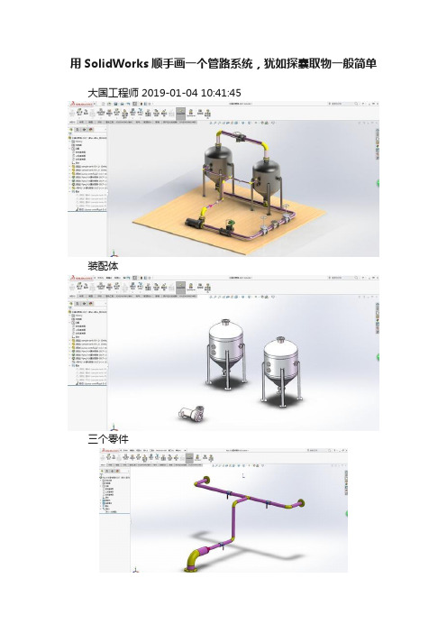
用SolidWorks顺手画一个管路系统,犹如探囊取物一般简单大国工程师 2019-01-04 10:41:45装配体三个零件管路1管路2管路3建模过程:画图前先在插件里打开管路插件——Routing 此图用的是SolidWorks2017版此图用到的所有零件都是软件自带的1.新建装配体,在设计库里找到routing ——piping——equipment把里面的水罐和水泵拖到装配体当中软件提示要先保存装配体,那就保存吧当拖入水灌水,软件提示插入一个新线路的子装配体,这里只要水罐的零件,不要子装配体,所以点红叉。
再复制一个水罐,同样只要零件,不要子装配体拖入水泵,只要零件,不要管路的子装配体2.用配合调整三个零件的位置,然后固定。
水泵距离水罐远一点,方便后面的操作。
3.在piping——flanges拖出一个法兰。
当靠近水罐的法兰时,软件会自动选择规格并配合。
4.因为这次要生成一个管路的子装配体,所以要打钩。
5.给另一个水罐也拖一个法兰。
6.用草图的直线连接两个端点,便会自动生成管道。
7.给水泵添加一个法兰。
8.草绘直线后自动生成管道。
9.但是水泵的管道太粗,无法和水罐的管道连接。
这里添加一个变径接头( piping——reducers ) 。
直接把接头拖到管道上就行。
10.再给水罐之间的管道添加一个三通,按Tab键可以切换三通的方向。
11.两个草图相交,剪裁,再添加一个圆角。
12.给管道上在添加几个阀门。
13.第一条管道完成,退出草图。
退出编辑红圈里的子装配体就是上面绘制的管路14.可以开始绘制第二条管路了。
15.给水罐顶部添加两个法兰,用直线连接端点。
16.拖一个球阀到草图上。
17.退出草绘,拖出子装配编辑,第二个管路绘制完成。
18.还可以再绘制第三条管路,方法是相同的。
先给水罐底部添加两个法兰和一个三通再给水泵侧面添加一个法兰然后用直线连接再给线路上拖一些其他东西19.完成,此图包含三个大零件(水罐和水泵),3个管路子装配体(每个子装配体里有许多软件生成的零件和路线)。
SW routing tutorial

SolidWorks Piping(routing)管道设计教程第一部分 简介通过Solidworks Piping 设计复杂管道系统。
此软件中还备有装置库,让设计过程变得更加轻松。
Solidworks Piping 可嵌入S01idworks 其他软件中。
加速绘制、修饰、装配输送营和设计管道路线的过程c 改进设计质量祀避免错误。
Solidworks piping 软件可让您以低廉的成本、在极短的时间内将产品完成推向市场。
以前,利用三维模型绘制软件设计输送管及其他构成部分并不是一件容易的事。
现在有了Solidworks Piping 这套设计软件'其自动操作的设计功能使设计工作变得轻松愉快。
Solidworks Piping 是一个强有力的专用设计管道系统的选加应用软件,并带有装置库。
SolidWorks Piping 的功能和益处包括:-通过自动设计营造系统的功能提高生产力-以直接,单击并拖放方式的组装与修饰功能-完备而标准的焊接与装置库,让您瞬间完成设计-自动选择装置-找出输送管管道与装置之间的变量与联系关系-以SolidWorks 绘制的管道系统与使用仪器(P&ID)可完全嵌入微软视窗提高设计的生产力SolidWorks Piping 让您通过三维绘图器简单地描出输送管的中心线,SolidWorks Piping 将会自动绘制出准确的割切长度并在每一个输送管弯曲处自动插入肘部。
另外、增强的形象化功能、准确性干涉检测功能与大量特性计算。
当您的设计需要渗透管道,无需装置的时候SolidWorks Piping 将会自动作出调整,将所有的输送管及其各大小部分组装起来。
SolidWorks Piping 可通过以下各种简单自动化的功能提高您设计的生产力。
-制造准确割切长度的导管-于弯曲处自动插入肘部-弯曲角度偏离标准角度的时候、可特别定制的部-利用SmartMates 的功能,用户可以单击并拖动的方式插入装置-制造输送管与输送管之间的渗透割切-利用单击并拖动的功能修改现有的管道系统直观设计和修改可提高设计质量通过Solidworks Piping 设计复杂管道系统。
solidworks管道设计教程
solidworks管道设计教程
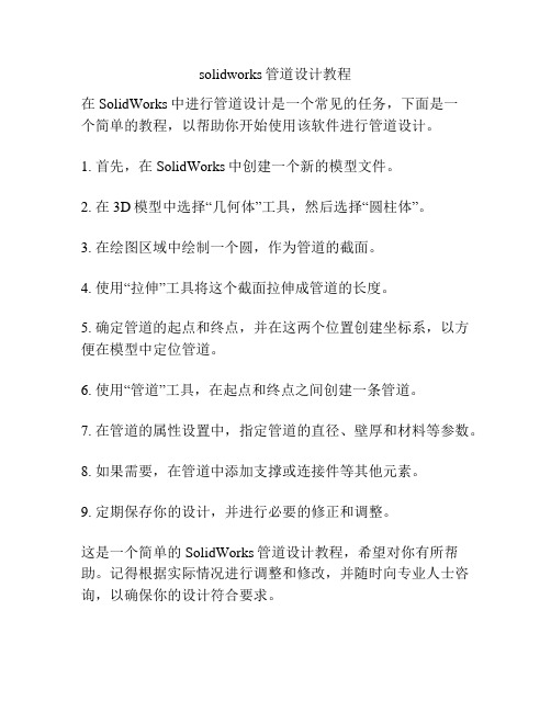
在SolidWorks中进行管道设计是一个常见的任务,下面是一
个简单的教程,以帮助你开始使用该软件进行管道设计。
1. 首先,在SolidWorks中创建一个新的模型文件。
2. 在3D模型中选择“几何体”工具,然后选择“圆柱体”。
3. 在绘图区域中绘制一个圆,作为管道的截面。
4. 使用“拉伸”工具将这个截面拉伸成管道的长度。
5. 确定管道的起点和终点,并在这两个位置创建坐标系,以方便在模型中定位管道。
6. 使用“管道”工具,在起点和终点之间创建一条管道。
7. 在管道的属性设置中,指定管道的直径、壁厚和材料等参数。
8. 如果需要,在管道中添加支撑或连接件等其他元素。
9. 定期保存你的设计,并进行必要的修正和调整。
这是一个简单的SolidWorks管道设计教程,希望对你有所帮助。
记得根据实际情况进行调整和修改,并随时向专业人士咨询,以确保你的设计符合要求。
solidworks管道routing培训
精品文档
2
二、如何使用
使用solidworks Routing绘制液压软管 1.打开solidworks软件 2.选择下拉菜单中的【工具】【插件】命令,在【插件】对话框中选中 【SolidWorks Routing】复选框,单击【确定】按钮即可启动 。
精品文档
3
二、如何使用
3.在软管接头上创建连接点和线路点(连接点:管道由此开始或终止) 选择下拉菜单中的【工具】---【Routing】 ---【Routing工具】 ---【生成 连接点】-----选择一个管道开始或截止的面----点击【选择管筒】
精品文档
7
二、如何使用
7.选中一个接头,右键选择开始步路
精品文档
8
二、如何使用
8.勾选使用软管,完成
精品文档
9
二、如何使用
9.选中另一个接头,右键选择添加到线路
精品文档
10
二、如何使用
10.在任意位置右击,选择自动步路,选择接头上的两个点
精品文档
11
二、如何使用
11.此时会自动生成管道,而且在管接头移动时,软管会跟 着变
精品文档
4
二、如何使用
4.以M36的软管接头,一层钢丝胶管为例,查样本知外径1.5in 壁厚 0.28in, 在管筒中选择对应参数
精品文档
5
二、如何使用
5.按上述方法添加软管另一端的接头的连接点,注意同一软管的 属性参数要一致。
精品文档
6
二、如何使用
6.开始绘制软管 创建一装配体,将两个接头装配进来
SolidWorks routing管道设计教程
精品文档
1
一、概述
SolidWorks Routing 是 SolidWorks 专门用于管路系统设计的一个插件, 完全 与 SolidWorks 无缝集成。利用 SolidWorks Routing,可以快速、 高效地完成大部分 用于气体和液体传输设备的管路系统。使用此插件可 以快速绘制复杂走向的钢管和软管,相比CAD绘制的平面管路,直观明 了。
solidworks布管教程
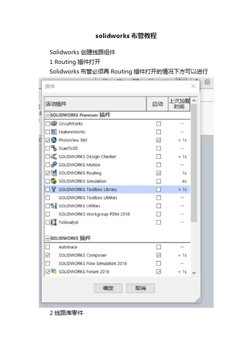
solidworks布管教程Solidworks 创建线路组件1 Routing插件打开Solidworks布管必须再Routing插件打开的情况下方可以进行2 线路库零件本部分讨论管道和管筒零件库零件。
这些零件包括SolidWorks安装时自带的零件、培训使用的例子及用户自己创建的零件。
Solid Works提供的设计库零件和装配体中包括普通尺寸的软管、电线、硬管以及配套的接头。
管道库存放位置一般在:C:\Documents and Settings\All Users\ApplicationData\SolidWorks\SolidWorks 2010\design library\routing1.管道库以solidWorks或其他通用格式存储的零件,通常SolidWorks管路模块可以直接使用。
3创建线路库零件线路库零件可在需要的时候创建,包括普通类型(比如管道、弯管)和不能用零部件向导创建的接头装配体。
复制和编辑尽管可以重新建立新零件,但大多数情况下还是复制一个相似的零件然后修改它比较容易3.1 线路库管理器线路库管理器是一个应用程序,运行在一个独立的窗口中,并包含几个线路零部件向导的选项卡。
使用向导创建线路零部件很多线路需要的零部件都可以通过线路零部件向导创建。
所有的零部件都包含设计表和零件属性选项。
4管道4.1硬管和软管零件创建的硬管和软管零件用于管路系统。
在创建线路时,它们被用于沿着3D草图产生的管道。
为了确保最后完成的零部件能被识别为线路零部件,对尺寸、草图和特征的特定命名很重要。
一般来说,创建新的线路零部件的最好方法是复制现有的线路零部件,然后对复件进行编样。
4.2 硬管和软管比较尽管硬管和软管使用类似的草图,但是它们的创建方式不一样,硬管使用【拉伸】特征,而软管使用【扫描】特征。
硬管只能沿着直线布管.因此使用拉伸特征;软管可以沿着直线、辐射线或者曲线路径布管,因此使用扫描特征。
SolidWorks管道设计教程

S o l i d W o r k s管道设计教程Document number:WTWYT-WYWY-BTGTT-YTTYU-2018GTSolidWorks Piping(routing)管道设计教程第一部分简介通过Solidworks Piping 设计复杂管道系统。
此软件中还备有装置库,让设计过程变得更加轻松。
Solidworks Piping 可嵌入S01idworks 其他软件中。
加速绘制、修饰、装配输送营和设计管道路线的过程c 改进设计质量祀避免错误。
Solidworks piping 软件可让您以低廉的成本、在极短的时间内将产品完成推向市场。
以前,利用三维模型绘制软件设计输送管及其他构成部分并不是一件容易的事。
现在有了Solidworks Piping 这套设计软件'其自动操作的设计功能使设计工作变得轻松愉快。
Solidworks Piping 是一个强有力的专用设计管道系统的选加应用软件,并带有装置库。
SolidWorks Piping 的功能和益处包括:-通过自动设计营造系统的功能提高生产力-以直接,单击并拖放方式的组装与修饰功能-完备而标准的焊接与装置库,让您瞬间完成设计-自动选择装置-找出输送管管道与装置之间的变量与联系关系-以SolidWorks 绘制的管道系统与使用仪器(P&ID)可完全嵌入微软视窗提高设计的生产力SolidWorks Piping 让您通过三维绘图器简单地描出输送管的中心线,SolidWorks Piping 将会自动绘制出准确的割切长度并在每一个输送管弯曲处自动插入肘部。
另外、增强的形象化功能、准确性干涉检测功能与大量特性计算。
当您的设计需要渗透管道,无需装置的时候SolidWorks Piping 将会自动作出调整, 将所有的输送管及其各大小部分组装起来。
SolidWorks Piping 可通过以下各种简单自动化的功能提高您设计的生产力。
SolidWorks管道设计教程
SolidWorks管道设计教程SolidWorks Piping(routing)管道设计教程第一部分简介通过Solidworks Piping 设计复杂管道系统。
此软件中还备有装置库,让设计过程变得更加轻松。
Solidworks Piping 可嵌入S01idworks 其他软件中。
加速绘制、修饰、装配输送营和设计管道路线的过程c 改进设计质量祀避免错误。
Solidworks piping 软件可让您以低廉的成本、在极短的时间内将产品完成推向市场。
以前,利用三维模型绘制软件设计输送管及其他构成部分并不是一件容易的事。
现在有了Solidworks Piping 这套设计软件'其自动操作的设计功能使设计工作变得轻松愉快。
Solidworks Piping 是一个强有力的专用设计管道系统的选加应用软件,并带有装置库。
SolidWorks Piping 的功能和益处包括:-通过自动设计营造系统的功能提高生产力-以直接,单击并拖放方式的组装与修饰功能-完备而标准的焊接与装置库,让您瞬间完成设计-自动选择装置-找出输送管管道与装置之间的变量与联系关系-以SolidWorks 绘制的管道系统与使用仪器(P&ID)可完全嵌入微软视窗提高设计的生产力SolidWorks Piping 让您通过三维绘图器简单地描出输送管的中心线,SolidWorks Piping 将会自动绘制出准确的割切长度并在每一个输送管弯曲处自动插入肘部。
另外、增强的形象化功能、准确性干涉检测功能与大量特性计算。
当您的设计需要渗透管道,无需装置的时候SolidWorks Piping 将会自动作出调整,将所有的输送管及其各大小部分组装起来。
SolidWorks Piping 可通过以下各种简单自动化的功能提高您设计的生产力。
-制造准确割切长度的导管-于弯曲处自动插入肘部-弯曲角度偏离标准角度的时候、可特别定制的部-利用SmartMates 的功能,用户可以单击并拖动的方式插入装置-制造输送管与输送管之间的渗透割切-利用单击并拖动的功能修改现有的管道系统直观设计和修改可提高设计质量通过Solidworks Piping 设计复杂管道系统。
- 1、下载文档前请自行甄别文档内容的完整性,平台不提供额外的编辑、内容补充、找答案等附加服务。
- 2、"仅部分预览"的文档,不可在线预览部分如存在完整性等问题,可反馈申请退款(可完整预览的文档不适用该条件!)。
- 3、如文档侵犯您的权益,请联系客服反馈,我们会尽快为您处理(人工客服工作时间:9:00-18:30)。
管子 拉伸特征 拉伸特征草图 构造圆草图 拉伸长度尺寸 拉伸草图内径 拉伸草图外径 构造圆草图直径 零件属性① 零件属性②
© 2006 SolidWorks Corp. Confidential.
9Leabharlann 第2章 内容要点 如何开始管路设计 插入第一个管路零件 管路属性设置 建立连接点 利用不同基准面制作3D草图 制作简单的管路
© 2006 SolidWorks Corp. Confidential.
6
第 3 章 管路库零件的制作
Image courtesy of National Optical Astronomy Observatory, operated by the Association of Universities for Research in Astronomy, under cooperative agreement with the National Science Foundation.
高级培训内容提纲:
培训内容
了解管路 简单管路 管路零件的制作
时间(分钟) 30 60 60
© 2006 SolidWorks Corp. Confidential.
2
第 1 章 了解管路
Image courtesy of National Optical Astronomy Observatory, operated by the Association of Universities for Research in Astronomy, under cooperative agreement with the National Science Foundation.
SolidWorks 2011 焊件、Routing
何坚俊 杭州华睿信息技术有限公司 hejj@
Image courtesy of National Optical Astronomy Observatory, operated by the Association of Universities for Research in Astronomy, under cooperative agreement with the National Science Foundation.
第1章 内容要点
了解管路插件及其工作模式 管路的分类
管路、管筒、电力
步路库的设置 界面及工具条
© 2006 SolidWorks Corp. Confidential.
4
第 2章 开始制作简单管路
Image courtesy of National Optical Astronomy Observatory, operated by the Association of Universities for Research in Astronomy, under cooperative agreement with the National Science Foundation.
第3章 内容要点
管子和弯头的制作 法拉、接头的制作
连接点和线路点的作用
异径接头的制作
© 2006 SolidWorks Corp. Confidential.
8
第3章 内容要点
制作管路零件
接头 Extrusion PipeSketch FilterSketch Length InnerDiameter OuterDiameter NominalDiameter Pipe Identifier SWbompartno 路径草图 轮廓草图 轮廓草图内径 轮廓草图外径 路径草图角度 路径草图半径 ElbowArc Route InnerDiameter O OuterDiameter Di BendAngle B dR di BendRadius