BT1207SA-PA(8645)蓝牙模块规格书1.0
新日本电器有限公司微波分支公司的NJR4265R系列K-Band微波智能运动传感器模块说明书
© Copyright 2017New Japan Radio Co., Ltd.Microwave Division-Notice of Proprietary Information-Documents and contents are proprietary to New Japan Radio Co., Ltd. This publication and its contents may not be reproduced or distributed for any other purpose without the written permission of New Japan Radio Co., Ltd.24GHz Microwave Intelligent Motion Sensorfor Short Distance, Low Speed ApplicationsNJR4265R is intelligent motion sensor that is designed for the sensing of short distance low speed movement object of pedestrian etc. The steady sensing of moving object is realized by embedded software. It is suitable for the built-in use of the sensing function to various equipment as all functions are integrated in a small package and it can easily control from PC/MCU by UART interface. Further, stand-alone operation is also possible.Features:●M otion sensor using the 24GHz Microwave Doppler ●Antenna, RF circuit, IF amp, MCU and voltageregulator are integrated in a small package(14 x 20.4 x 8.8mm)●Communication with PC/MCU is available byUART interface and stand-alone operation is also possible●S ignal processing software for the steady sensing Enhancing the signal from movement object and decreasing random noisesDecreasing the mutual interference between sensorsI dentification of direction for movement object(approaching and leaving).●L ow voltage operation and low power consumption ●S leep mode for reducing power when unnecessary Applications:●Various equipment control by human sensing Energy saving managementEntrance and exit managementSafety and SecurityFunctional Brock diagram:Products Line-up:●Model Numbering System●Model Number List*Note: The Model of FCC certification (Model No. NJR4265RF3C1) must refer to Appendix of “FCC Statement of NJR4265RF3”.●Evaluation KitThe evaluation kit is available for NJR4265R series. The contents of the evaluation kit are as follows.Evaluation Kit P/N.: NJR4265J1KContents1.Sensor Module2.Evaluation Board (Functions are UART-to-USB convertor and analog threshold setting)3.GUI SoftwareB Cable1.Absolute Maximum RatingITEM MIN. TYP. MAX. UNITS REMARKS Supply Voltage 0 ― 6.5 VOperating Temperature -40 ―+85 °CStorage Temperature -40 ―+85 °C2.Electrical CharacteristicsPower SupplyOperating Voltage 3.0 3.3/5.0 5.25 VOperating CurrentSensing mode ―60 ―mASleep mode ― 4 ―mASensor RFConformity Standard ●EU Certification: Radio Equipment Directive 2014/53/EU●FCC Certification: Part 15.245●MIC Technical Conformity (Japan): ARIB STD-T73Operating FrequencyF1 type 24.05 ―24.25 GHz EU Certification F2 type 24.15 ―24.25 GHzF3 type 24.075 ―24.175 GHz FCC Certification J1 type 24.05 ―24.25 GHz Japan Certification Frequency Stability (Temp.) ―+/-0.2 ―MHz/°C T a=-20to +60 °C Output Power (E.I.R.P.) 8.2 ―13 dBm2nd Harmonics (E.I.R.P.) ――-30 dBmAntenna-3dB beam width (Horizontal)―70 ―deg.-3dB beam width (Vertical) ―54 ―deg.―――dB No Side lobe Side lobe suppression(Horizontal)Side lobe suppression―――dB No Side lobe (Vertical)Typical Radiation Pattern3.Environmental characteristicsITEM SPECIFICATIONOperation Temperature -20 to +60 °CStorage Temperature -40 to +80 °CHumidity 0 to 95 %@+30 °CVibration 49.03 m/s2(5 G), 30 to 50 Hz, 10 minutes, XYZ direction Shock 196.13 m/s2(20 G), Half sine, 11 ms, XYZ direction, 3 times4. Sensing PerformanceCommon measure condition Ta= +25 °C ITEMPERFORMANCE UNITS REMARKSSpeed Range of T arget0.25 to 1.0m/s Maximum Distance in Front 10 m Detectable Angle+/-35deg.*Note) This is not the specification to guarantee the performance of this product. As for the specification of theproduct, the electric characteristic standard is applied. Sensing performance shown here is an example of the result of being likely to obtain it when this product is used on the following conditions. Actual sensing performance would be greatly different in each environment used.Please do enough confirmation in the environment actually used.Definition of Sensing Performance* Speed Range of T arget: The range of the speed that the detection distance become 70% of the detection distance of 0.5 m/s* Maximum Distance in Front:Detectable distance that can be detected in front of sensor when a threshold value set to [999] or when VDD is added to a threshold setting terminal* Detectable Angle:Angle where detection distance becomes 70% of the frontMeasurement condition of detection performance* Temperature:T a = +25 °C* T arget of Measurement: An adult of 170cm/70kg approaching at the rate of 0.5m/s from the front of sensor* Installation of the Sensor:T he sensor is installed as the antennas horizontal horizontally in a height of 1 m from the ground.Weight 70kgTop ViewSide View5.Signal processing for the steady sensing of moving objectThis product is embedding software for the steady sensing of moving object. It is enhance the signal from movement object of pedestrian etc. and is reduce random noise and sudden signal which caused an incorrect detection by using the signal from IQ mixer, namely Environmental Noise Reduction.The following effects are expectable.●Reduction of false detection by random movement such as the shakes of plant by wind or thenoise of rain etc.●Reduction of the false detection by sudden movement such as the insect etc. which cross justbefore a sensor●Steady detection of movement objects such as pedestrian under the environment where theabove-mentioned noise exists.●Reduction of the mutual interference of sensors●Identification of direction of movement (approach and leaving)*Note) This signal processing function assumes the following noises are reduced, and pedestrian's movement is emphasized. However, it is likely to become a counter productivity for a signal outside assumption.6. Interface6.1. Pin AssignmentPin diagram (Bottom View)# NAMEI/O DESCRIPTION 1Option― Option PinOption pin is not assigned at NJR4265R. Keep it in electrically open state 2 TxD (UART) O UART TxD 3 RxD (UART)I UART RxD4Threshold SettingI Analog threshold voltage (V TH )Available to set by the voltage applied to this pin.Threshold of detection distance = V TH / V DD x 10 m *Note1 5 Detect(approaching) O Output for approaching detection *Note2H: Detect / L: No detect6 Detect (leaving) O Output for leaving detection *Note2H: Detect / L: No detect7 VDD I Power Supply Input (V DD ): 3.0 to 5.25 V 8 ― ― Internal connection *Note3DO NOT connect any signal lines including GND. 9 ― ― 10 ― ― 11 GND―GND Pin*Note1) Detection distance assumes the case that an adult of 170cm/70kg approaches at the rate of 0.5m/sfrom the front.*Note2) Pin 5 or 6 is changed to H level respectively when the movements of approaching or leaving isdetected. (Output current < 5mA)*Note3) Pin 8, 9 and10 are used for internal connection. Those must be electrically open independently. Thesepins must use the via holes of an independent pad when the sensor install on a PCB. Do not connect also between these terminals too.6.2.Asynchronous Serial Data Bus (UART) InterfaceNJR4265R is able to control of sensor mode, set of threshold level, acquisition of detection result and Communication ParametersBaud Rates 9600 bpsData Bits 8 bitsStop Bits 1 bitsParity odd ―Handshake non ―Byte Order LSB ―7. Operational modeMODEDESCRIPTIONPower ON / Reset CPU Reset.Initialization Mode Initialize and wait until sensor is stabilized.Notice command is sent out after the completion of initialization.Detection ModeDetection command is sent when following changes arise in the state of the sensor detection.1. detect approaching object2. detect leaving object3. state change from detection to no-detectionSleep ModeShutdown of all analog circuit for reducing the current.When returning to detection mode, about one second needs for stabilization of the sensor .*Note) When the watch dog timer overflows, it is reset from any mode●The default detection mode at the Power-on or CPU reset is analog threshold mode. It is possible to change to the command threshold mode by sending parameter setting commands. (@SP, @SM and @SC)● The @SA command is effective when changing from the command threshold to an analog threshold mode.●When mode is changed to sleep mode or is resumed from sleep mode, the threshold mode is preserved. Moreover, the change of the threshold mode in sleep mode is also possible.State Transition Diagram State Transition Tablemunication command8.1.OutlineCOMMAND TYPE DIRECTION DESCRIPTION EFFECTIVE MODE Detection Sensor to Host Sending from sensor when movementis detectedDetection modeMode Change Host to Sensor Change the sensor mode Detection modeSleep mode Parameter Setting Host to Sensor Setting and change of thresholdparametersQuery Sensor to HostHost to Sensor Reading of state of sensor (mode , parameters)Reset Host to Sensor Reset of sensorStart Notification Sensor to Host Sending from sensor when initializationis completed InitializationmodeError Response Sensor to Host Sending from sensor when error occurs All modemunication Command ListBoth Sensor-to-Host (S-to-H) and Host-to-sensor (H-to-S) use the following formats.@ XXX xx <CR><LF>@: Command headerXXX: Command characters, alphabet 1-3 characters. (Capital letter and small letter are Distinguished.)xx: Command/configuration parameters (numerical value or alphabet onecharacter or “?”.)<CR><LF>: Delimiter (CR+LF)Query CommandsAcquire the present detection Q1 H-to-S @Q1?<CR><LF>Response of present detection S-to-H @C<CR><LF> Approaching@L<CR><LF> Leaving@N<CR><LF> No detection Acquire the present mode Q2 H-to-S @Q2?<CR><LF>Response of present mode S-to-H @T<CR><LF> Detection mode@U<CR><LF> Sleep modeCONTENTS/EFFECTS XXX DIRECTION FORMAT REMARKS Acquire the present threshold mode Q6 H-to-S @Q6?<CR><LF>Response of present threshold mode S-to-H @SA<CR><LF> Analog threshold@SC<CR><LF> Command threshold Acquire the Approaching threshold SP H-to-S @SP?<CR><LF>Response of Approaching threshold S-to-H @SPxxx<CR><LF> *Note1Acquire the Leaving threshold SM H-to-S @SM?<CR><LF>Response of Leaving threshold S-to-H @SMxxx<CR><LF> *Note1Acquire the Analog threshold SV H-to-S @SV?<CR><LF>Response Analog threshold S-to-H @SVxxxx<CR><LF>Value of ADC Acquire the software version V H-to-S @V?<CR><LF>Response of software version S-to-H @Vx.xx<CR><LF> x.xx: Version Reset Command, Start Notification CommandError Response CommandsNotification of UART framing error EF S-to-H @EF<CR><LF>Notification of UART parity error EP S-to-H @EP<CR><LF>Notification of Communication error ER S-to-H @EP<CR><LF>Notification of Self-test ES S-to-H @ER<CR><LF>Notification of watch dog timer error EW S-to-H @EW<CR><LF>*Note1) Capable threshold setting range is Integer 1-999.The relation between the threshold value and the detection distance (*Note2) can be shown by the following expressions:Da =SP/100, [Da] is approaching detection distance (units: m)Dl = SM/100, [Dl] is leaving detection distance (units: m)*Note2) Detection distance assumes the case that an adult of 170cm/70kg approaches at the rate of 0.5m/s from the front.9.Drawing 9.1.Outline10.PackageStandard PackagePacking Quantity: 500 pieces per shipping box11.Reference Circuit11.1.Example of connecting with MCU11.2.Example of using it by stand-alone12.Recommendation Mounting Conditions12.1.Footprint dimensions*Note) In actual design, please optimize in accordance with the situation of your board design and soldering condition.12.2.Soldering conditions●Soldering way: Solder iron *Note●Solder iron temperature: 350 °C or less●Mounting time: 3 second or less per pin*Note) The soldering iron to be used must be grounded via a resistance of about 1 MΩ.Appendix)FCC Statement of NJR4265RF3Rev. 2.0July 11, 2017 Responsible party:New Japan Radio Co.,Ltd.1-1, Fukuoka 2-chome Fujimino city Saitama JapanTel: +81-49-278-1271, Fax: +81-49-278-1234This device complies with Part 15 of the FCC rules. Operation is a subject to the following two conditions:(1) This device may not cause harmful interference.(2) This device must accept any interference received, includinginterference that may cause undesired operation.CautionDC power supply for each module should be conformed to the electricalspecifications as described in this section. A host in which a module isintegrated should provide stable DC power through suitable regulatorcircuit to the module.NOTE:Changes or modifications to the device not expressly approved by the party responsible for compliance could void the user’s authority to operate the equipment(s).This equipment has been tested and found to comply with the limits for a Class B digitaldevice, pursuant to part 15 of the FCC Rules. These limits are designed to provide reasonable protection against harmful interference in a residential installation. This equipment generates, uses and canradiateradio frequency energy and, if not installed and used in accordance with the instructions, may cause harmful interference to radiocommunications. However, there is no guarantee that interference will not occur in a particular installation. If this equipment does cause harmfulinterference to radio or television reception, which can be determined by turning the equipment off and on, the user is encouraged to try to correct the interference by one or more of the following measures:— Reorient or relocate the receiving antenna.— Increase the separation between the equipment and receiver.— Connect the equipment into an outlet on a circuit different from that to which the receiver is connected.— Consult the dealer or an experienced radio/TV technician for help.The equipment complies with radio frequency exposure limits set forth by the FCC for an uncontrolled environment.The device must not be co-located or operating in conjunction with anyother antenna or transmitter.。
NCP1207A中文资料

5.0 ms Timeout
Timeout Reset
380 ns
L.E.B.
CS
Demag
ÁÁÁÁÁÁMAÁÁÁXIMÁÁÁUMÁÁÁRATÁÁÁINGÁÁÁS ÁÁÁÁÁÁÁÁÁÁÁÁÁÁÁFRiÁÁÁgautirnÁÁÁeg2.ÁÁÁInteÁÁÁrnaÁÁÁl CiÁÁÁrcuiÁÁÁt ArÁÁÁchitÁÁÁectÁÁÁureÁÁÁÁÁÁÁÁÁÁÁÁSymÁÁÁbolÁÁÁÁÁÁVaÁÁlÁue ÁÁÁÁÁÁUniÁÁtÁs
© Semiconductor Components Industries, LLC, 2004
1
November, 2004 − Rev. 1
Publication Order Number: NCP1207A/D
元器件交易网
NCP1207A
Universal Network
NCP1207ADR2 SOIC−8 2500/Tape & Reel
NCP1207ADR2G NCP1207AP
SOIC−8 (Pb−Free)
PDIP−8
2500/Tape & Reel 50 Units/Tube
†For information on tape and reel specifications, including part orientation and tape sizes, please refer to our Tape and Reel Packaging Specifications Brochure, BRD8011/D.
2
FB
Sets the peak current setpoint By connecting an Optocoupler to this pin, the peak current setpoint is
BT-120中文资料
©2008 Amp’ed RF Inc
1722 Ringwood Ave, Suite 250, San Jose, CA 95131, USA
BT-120/121 Datasheet Page 5 of 6
元器件交易网
Amp’ed RF, Inc.
元器件交易网
Amp’ed RF, Inc.
(phone) 408 213-9530 (fax) 408 213-9533
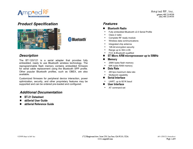
Product Specification
Features
Bluetooth Radio
Fully embedded Bluetooth v2.0 Serial Profile Class 2 radio Complete RF ready module Wireless data communications Integrated chip antenna 128-bit encryption security Range up to 30m LOS FCC & Bluetooth qualified
1722 Ringwood Ave, Suite 250, San Jose, CA 95131, USA
BT-120/121 Datasheet Page 4 of 6
元器件交易网
Amp’ed RF, Inc.
(phone) 408 213-9530 (fax) 408 213-9533
BT-120/121 Datasheet Page 2 of 6
元器件交易网
Amp’ed RF, Inc.
(phone) 408 213-9530 (fax) 408 213-9533
Serial Interface AT Commands
启英泰伦双麦离在线语音识别模组硬件规格书 CI-B03ST01S-BK说明书

双麦离在线语音识别模组硬件规格书型号:CI-B03ST01S-BK版本:V1.0文件历史跟踪DOCUMENT HISTORY PAGE版本号Rev.NO.发起者Originator描述Description日期Date V1.0启英泰伦新建文档2020/05/10声明本手册由成都启英泰伦科技有限公司版权所有,未经许可,任何单位和个人都不得以电子的、机械的、磁性的、光学的、化学的、手工的等形式复制、传播、转录和保存该出版物,或翻译成其他语言版本。
一经发现,将追究其法律责任。
启英泰伦保留更改本手册的权利,请在订购时联系我们以获得产品最新信息。
对任何用户使用我们产品时侵犯第三方版权或其他权利的行为本公司概不负责。
另外,在启英泰伦未明确表示产品有该项用途时,对于产品使用在极端条件下导致一些失灵或损毁而造成的损失概不负责。
目录1概述 (5)2模组主芯片描述 (7)3模组实物图 (10)4硬件接口定义 (12)5电路设计参考 (15)5.1电源 (15)5.2ADC接口 (15)5.3升级接口 (15)5.4PWM (15)5.5ESD设计 (15)5.6GPIO (16)5.7UART (16)5.8I2S音频接口 (16)5.9调试接口 (16)5.10DAC输出 (16)6电气参数 (17)7使用注意事项 (18)Chipintelli Technology Co.,Ltd.CONFIDENTIAL ALL RIGHTS RESERVED.This document is not to be reproduced,modified,adapted,published, translated in any material form in whole or in part nor disclosed to any third party without the prior writtenpermission of Chipintelli Technology Co.,Ltd.1概述启英泰伦双麦离在线语音识别模组CI-B03ST01S-BK是针对离在线应用开发的一款通用、便携、低功耗高性能语音识别模组,该模组具有以下功能和特点:⏹模组搭载高性能CI1103语音识别芯片,通过该芯片内置的基于深度神经网络(DNN)的硬件处理器,内置100条命令词离线语音识别功能,不依赖网络,时延小,且可保护用户隐私。
HC-8645 蓝牙音频模块规格书

HC-8645Bluetooth module specificationsBluetooth®4.0Bluetooth®3.0Type:Document Number:Version:Release Date:(2013-03-01new)Authors:※Does if there are any new version,without prior notice.1、DescriptionHC-8645is a our next generation Stereo ROM solution with aptX®CODEC technology that sets a new standard for wired or wireless stereo audio quality,which customers can use to more easily,quickly and cost effectively bring to market a range of highly differentiated home entertainment and wearable audio products.Figure1:HC-8645Bluetooth module2、Features■80MHz RISC MCU and80MIPS Kalimba DSP■Stereo codec with2microphone inputs■5-band fully configurable EQ■CSR's latest CVC technology for narrowband and wideband voice connections including wind noise reduction■Wideband speech supported by HFP v1.6profile and mSBC codec■Voice recognition support for answering a call,enables true hands-free use■Multipoint HFP connection to2phones for voice■Multipoint A2DP connection enables a headset(A2DP)connection to2A2DP sourcedevices for music playback■Secure simple pairing,CSR's proximity pairing and CSR's proximity connection■Audio interfaces:I²S and PCM■Serial interfaces:UART,USB v2.0(full-speed),I²C and SPI■aptX,SBC,MP3and AAC decoder support■Wired audio support(USB and analogue)■Support for smartphone/tablet applications■Integrated dual switch-mode regulators,linear regulators and battery charger■3LED outputs■Green(RoHS compliant and no antimony or halogenated flame retardants)3、Applications■Stereo headsets■Wired stereo headsets and headphones■Portable stereo speakers5、System Block DiagramFigure2:HC-8645System Block Diagram◇Bluetooth®4.0、Bluetooth®3.0◇CSR8645Stereo ROM Solution with aptX®◇SUPPORT Piconet,up to7Slaves◇SUPPORT I nterfaces:UART and USB v2.0(full-speed)。
8752A-U硬件规格书 v 1.0

8752A-U低功耗蓝牙Mesh模组硬件规格书V1.0修改记录修改记录修改日期修改内容修改人审核人版本2018.8.20首次发行Allen V1.0目录前言 (4)版权声明 (4)1.引言 (5)2.模组结构图 (5)3.模组外观图 (6)4.模组主要特性 (7)5.引脚分配(正面图) (9)6.模组引脚描述 (10)7.硬件设计部分: (12)电源设计 (12)复位电路 (12)Uart通信接口 (13)I2C接口 (15)模数转换接口 (15)PWM接口 (16)天线接口 (16)订购信息 (19)推荐回流曲线 (20)附录:模组尺寸图 (21)前言非常感谢您选择并使用我公司的模组,此模组主要用于蓝牙数据通讯和Mesh组网的智能控制,是一款超紧凑、高性能、低功耗的带有Mesh组网功能的蓝牙通信组件。
模组由一颗高集成度的蓝牙芯片RTL8752CMF和少量的外围电路构成,内置了蓝牙网络通信协议栈和丰富的库函数,用户可在此基础上轻松实现蓝牙应用的开发,缩短研发周期。
同时模组尺寸紧凑,功能丰富,能最大限度地满足终端设备对小尺寸模组产品的需求,有效地帮助客户减小产品尺寸并优化产品成本。
使用前请仔细阅读本产品规格书,您将了解本模块的功能和简洁的操作方法。
本公司不承担由于用户不正常操作造成的财产损失或者人身伤害责任。
请用户按照手册中的技术规格和参考设计开发相应的产品。
引言本文档描述了模组的硬件应用接口,包括相关应用场合的电路连接以及射频接口等,可以帮助用户快速了解模组的接口定义、电气性能和结构尺寸等详细信息。
结合本文档和其他的应用文档,用户可以快速使用该模组来完成应用方案设计。
2.模组结构图图18752A-U模组结构图3.模组外观图图28752A-U模组外观图4.模组主要特性5.引脚分配(正面图)图38752A-U模组管脚图6.模组引脚描述I/O参数定义:IO双向端口DI数字输入DO数字输出PI电源输入PO电源输出AI模拟输入AO模拟输出7.硬件设计部分:电源设计8752A-U模组只需一路1.8~3.3V的电源连接相应的模块引脚即可工作,供电引脚如下:引脚名引脚编号I/O描述特性备注VBAT8PI模块供电Vmin=1.8vVtyp=3.0vVmax=3.3v 电源必须能够提供不小于50mA的电流GND2,5GNDGND模块VBAT的电压输入范围是1.8V到3.3V,推荐电压为3.0V。
Motorola T800 通信设备模块和配件技术说明书
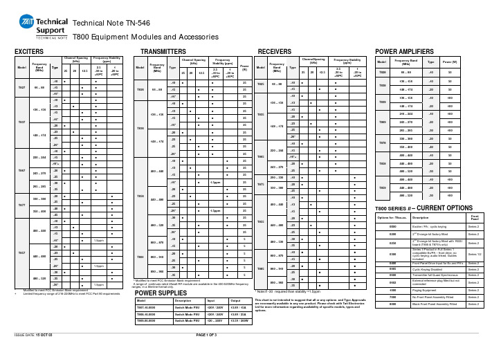
Technical Note TN-546T800 Equipment Modules and AccessoriesISSUE DATE: 15 OCT 03PAGE 1 OF 3EXCITERSChannel Spacing(kHz)Frequency Stability(ppm)ModelFrequency Band (MHz)Type252012.52.5-30 to +60°C1-20 to +60°C-10•• -15 • • T82766 – 88-16* • • -10• • -13 • • -15 • •136 – 156 -16* • •-20• • -23 • • -25 • •T 837148 – 174 -26* • •-10• • -15 • • 220 – 244-16*+ • • -20• •243 – 270 -25 • • -30• •T 867265 – 285-35• •-20• •330 – 380 -25 • • -40• •T 877350 – 400 -45 • • -10• • -13 • • -15 • •400 – 440 -16* • 1.5ppm-20• • -23 • • -25 • •440 – 480 -26* • 1.5ppm-30• • -35 • •T 857 480 – 520-36*•1.5ppm*Modified to meet FCC Emission Mask requirement+Limited frequency range of 216-220MHz to meet FCC Part 80 requirementsTRANSMITTERSC hannel Spacing (kHz)F requency Stability (ppm)M odel F requency Band(MHz)T ype 252012.52.5 –30 to +60°C1 –20 to +60°C P ower (W)-10•• 25 -15 • • 25T 82666 – 88 -16* ••25-10• • 25 -13 •• 25 -15 • • 25136 – 156 -16* • •25-20• • 25 -23 •• 25 -25 • • 25T 836 148 – 174-26* • •25-10• • 25 -13 •• 25 -15 •• 25400 – 440 -16* • 1.5ppm25-20• • 25 -23 •• 25 -25 •• 25440 – 480 -26* • 1.5ppm25-30• • 25 -35 • • 25T 856480 – 520-36* • 25-10• • 5800 – 870 -15 • • 5-20• •5860 – 910 -25 • • 5 -30• • 5 T 881890 – 960-35••5* Modified to meet FCC Emission Mask requirement A range of continues rated 25watt RF module are available in the 400-520MHz frequencyranges, in a Slimline format only.P OWER SUPPLIESM odelD escription I nput O utputT 807-10-0000S witch Mode PSU 120V / 240V 13.8V / 15AT 808-10-0000S witch Mode PSU 120V / 240V 13.8V / 25AT 809-00-0000S witch Mode PSU120 – 240V13.5V / 200WR ECEIVERSC hannelSpacing (kHz)F requency Stability(ppm)M odel F requency Band(MHz)T ype 252012.52.5 -30 to +60°C1 -20 to +60°C-10• •T 825 66 – 88-15 ••-10• • -13 ••136 – 156-15 • • -20• • -23 •• -25 • •T 835148 – 174 -26* • •-10•• -15 • •220 – 244 -16*+ • •-20• •T 865 243 – 270 -25 • •290 – 330 -10• • -20• •T 875330 – 380 -25 • •-10• • -13 • •400 – 440-15 • •-20• • -23 • •440 – 480-25 • • -30••T 855480 – 530 -35• •-10• •800 – 870 -15• • -20• •860 – 910 -25• • -30••T 885890 – 960-35••* Note:If -30° required than stability =1.5ppmThis chart is not intended to suggest that all or any options and Type Approvalsare necessarily available in any one product. Please check with Tait Electronics Ltd for more information regarding availability of specific models, types and options.POWER AMPLIFIERSM odel Frequency Band(MHz)TypePower (W)T82866 – 88-1050136 – 156-1050T838148 – 174-2050136 – 156-10100T839148 – 174-20100216 – 244-10100243 – 270-20100T869265 – 285-30100330 – 380-2050T878350 – 400-4050400 – 440-1050440 – 480-2050T858480 – 520-3050400 – 440-10100440 – 480-20100T859480 – 520-30100T800 SERIES II – CURRENT OPTIONSO ptions for: T8xx-xx-D escription FrontPanel 0X00Exciter / PA ; cyclic keying Series 202002nd D-range kit factory fittedSeries 202502ndD-range kit factory fitted with RSSIboard (T855 & T875’s only)Series 20300Series II Product in Full Series 1compatible Ex/PA – front drive; no cyclic keying; audio linked; Guides includedSeries 1/20400Front Panel Drive Input for Ex and PA’s Series 20005Cyclic Keying DisabledSeries 20600Transmitter full Quasi Synchronous Series 20602External reference plug fitted but not connected Series 21000Paging EquipmentSeries 27000No Front Panel Assembly Fitted Series 28000Black Front Panel Assembly FittedSeries 2T800 Series IIProgramming KitsT800-01-0002T800 programming cable onlyT800-01-0003T800 programming cable & module interfaceT800-01-0004T800 module interfaceT800-01-0005T800 Std. programming kit with CDT800-01-0006T800 programming kit & module interface General AncillariesT800-80-0000Local microphoneT800-80-0001Local microphone for T803-00-0000General Ancillary KitsT800-03-0000Auxiliary D-range kitT800-04-0000 RSSI assembly for T800 seriesT800-06-0000External Reference Input KitT800-06-0001External Reference Input Kit; with rack coax connector leadsT800-06-0002External Reference Input Kit; (Partial Fitted)T800-06-0003External Reference Input Kit; Dedicated Paging Exciter AssemblyT800-10-0000Channel Select PCB / InternalT818-01-0000 Tx / Rx Local Metering & Monitor unitT800-01-0010Desktop Calibration Test UnitT800-09-0000 Coaxial Relay with mounting BracketT800-09-0001Coaxial Relay with Rack mounting AssemblyT800-09-0002Coaxial Relay for Slimline ConfigurationsT800-16-0000Channel Change and Speaker Panel, 10 channels (BCD Switching)TA087-02-0000Channel Change and Speaker Panel, 100 channels (Enhanced)TA320-10-0000200W Power Combiner, 66 - 125MHzTA320-11-0000200W Power Combiner, 125 - 250MHzTA320-13-0000200 W Power Combiner, 300 - 550MHzTA703-01-0000Standard Changeover for two antennasTA703-01-0001Changeover 72-88MHzTA703-01-0002Changeover 132-174MHzTA703-01-0003Changeover 320-390MHzTA703-01-0004Changeover 400-512MHzTA703-01-0005Changeover 806-960MHzTA703-10-0010Power Monitor Kit 30-88MHzTA703-10-0011Power Monitor Kit 118-512MHzTA703-10-0012Power Monitor Kit 806-960MHzTA703-11-0010Changeover Installation Kit, T800-50-0000TA703-11-0011Changeover Installation Kit, T800-50-0001T803-02-0000Tone Remote and AlarmSeries 2 Front Panel Conversion Kits for Series 1 ModulesT800-70-0000ReceiverT800-71-0000TransmitterT800-72-0000Exciter (rear O/P)T800-73-0000Exciter (front O/P)T800-74-0000PA 50W (rear I/P)T800-75-0000PA 50W (front I/P)T800-76-0000PA 100W (rear I/P)T800-77-0000PA 100W (front I/P)Series 1 Front Panel Conversion Kits for Series 2 ModulesNumbering convention = T800-70-00XYX = T820 (Frequency Band)Y = T825 (Type)ExampleConverting a T825 Series II to a Series I front panel uses aT800-70-0025 Front Panel Conversion KitPower SupplyT807-10-00XX PSU Switch Mode 15Amps (5U Rack Mount)T808-10-00XX PSU Switch Mode 25Amps (5U Rack Mount)T809-00-0000PSU Switch Mode 14.5Amps 240v (5U Rack Mount)T800-23-0011Slimline PSU 13.5V 200W(XX = Power Cord Options)(00 = No Power Cord Supplied)(11 = Aus/NZ Power Cord)(12 = USA/Canada Power Cord)(13 = Open End Power Cord)RacksT800-22-0X00Std. Base Station / Repeater, assembledT800-22-0X06Repeater with link endT800-22-0X10Std. Base Station / Repeater 100W AC (Channel / Panel Option)T800-22-0X11Receiver x4 only with alarmsT800-22-0X12Receiver x4 onlyT800-22-0X14Dual 25W single Supply option with twospeakersT800-22-0X15Dual 25W dual Supply option with two wayswitchable speakerT800-22-0116Dual 50W external DC with two wayswitchable speakerT800-22-0018Dual 25/50W single PSU with two wayswitchable speakerT800-22-0X20Monitor rack max. 50WT800-22-0121Monitor rack 25W with external DCT800-22-0122Monitor Rack 50W with external DCT800-22-0X23Alarm Rack max. 50W (Outputs 0volts onAlarms)T800-22-0X24Alarm Rack max. 50W (Outputs Low onAlarms)T800-24-0X00QS Rack Tx only max. 100W, (alarm option)T800-24-0X01QS Rack Tx Dual 50W, no alarmsT800-24-0X02QS Rack Tx Dual 25/50W, Link RepeaterT800-24-0X03QS Rack Tx Single 100WT800-24-0090QS Rack Tx 50W including Mon. RX and PSU(alarm option)T800-24-0600QS Rack Monitor PSU, Dual receivers andPSU’s with AlarmsT800-24-0601QS Rack Monitor PSU, Dual receivers andPSU’s with No AlarmsT800-25-0001Portable Repeater max. 25W, External DC,PSU and battery backup used as a switchabletalk through repeaterT800-27-0X00Tone Remote / Alarm Dual 25WT800-27-0X01Tone Remote / Alarm max. 100WT800-28-0X00High Stability Oscillator Rack with SingleExternal ReferenceT800-28-0X01High Stability Oscillator Rack with DualExternal ReferenceT800-29-0X00Fylde Trunking Rack Dual 25WT800-29-0X01Fylde Trunking Rack Single 100W(X = Optional Power Inputs Available)Slimline AssembliesT800-23-0000Slimline assembly kit (Hand Wired)T800-23-0001Slimline assembly kit with PSU (Hand Wired)T800-23-100X Slimline assembly kit for Single 25watt PagingTransmitterT800-56-0002Slimline BSM Assembly and PSU (Black)T800-56-0004Slimline BSM Assembly DC only (Black)T800-56-0042Slimline BSM Assembly and PSU withChannel Change (Black)T800-56-0044Slimline BSM Assembly DC only with ChannelChange (Black)T800-56-9002Slimline BSM Assembly and PSU (ContinuosRated 25W)(Black)T800-56-9004Slimline BSM Assembly DC only (ContinuosRated 25W)(Black)T800-56-9012Slimline BSM Assembly and PSU with ToneRemote(Continuos Rated 25W)(Black)T800-56-9014Slimline BSM Assembly DC only with ToneRemote(Continuos Rated 25W)(Black)Rack AncillariesT800-08-0000Ancillary box with front panel assembly, T800ConfigurationT800-08-0001Ancillary box with front panel assembly, T300ConfigurationT800-11-0000DC rear rail assemblyT800-13-0000Extender rail kit with 2 D-range socketsT800-14-0000Extender rail with 11 Way D-Range forexternal referenceT800-17-0010Panel Circuit Breaker Kit 10 AmpT800-17-0020Panel Circuit Breaker Kit 20 AmpT800-17-0030Panel Circuit Breaker Kit 30 AmpT800-18-0001Converter Unit DC24/12v, 8Amps, 25w RacksOnlyT800-18-0004Converter Unit DC24/12v 14Amps, 50wRacks OnlyT800-18-0005Converter Unit DC48/12v 14Amps, 50wRacks OnlyT800-18-0008Converter Unit DC72/13.8v 15Amps, NotRack MountingT800-19-0000Rack Fan Kit Single - Rail mounted(horizontal)T800-19-0002Rack Fan Kit Dual - Rail mounted(horizontal)T800-19-0010Rack Fan Kit Single - Guide Mounting(horizontal)Front Panel KitsT800-15-0000Speaker / Programming portT800-15-0001Speaker OnlyT800-15-0002Speaker Programming Panel with 6 waymonitoring switchT800-15-0003Speaker Programming Panel with 2 waymonitoring switchT800-40-0000Fitting Kit only for Blank PanelT800-40-0001Blank Panel with Fitting KitRack PCB’sT800-50-0000Std. Rack Backplane PCBT800-50-0001Back Plane PCB with Channel PanelOptionsT800-50-0002Back Plane RX only with Channel Panel andAlarm optionsT800-50-0003Back Plane TX only with Channel Panel,Alarm and MonitorT800-50-0004Back Plane RX Single with Channel PanelT800-50-0005Back Plane TX Single with Channel PanelT800-52-0000Back Plane Quasi TX / Alarm / ChannelPanelT800-52-0002Back Plane TX only with External ReferenceT800-54-0000Back Plane Tone Remote for T803 ModuleT800-55-0000Back Plane Paging with External Referencefor HSO ModuleT800-55-0001Back Plane Dual RX/TX External ReferenceT800-57-0000Back Plane Fylde Trunking (TSC02EInterface)T800-60-0000Personality PCB for Monitor & ChannelSelectT800-60-0001Alarm Outputs (low) with Channel SelectionOptionT800-60-0002Alarm Outputs (Zero volts) with ChannelSelection OptionT800-60-0003Wide Band / Narrow Band SwitchingGuide KitsT800-41-0001Single Guide KitT800-41-0002Double Guide KitT800-41-0003Triple Guide KitT800-41-0004Quad Guide KitT800-42-0000Guide Only DuplexerT800-42-0001Guide Duplexer Kit - Duplexer/Panel + CoaxLeadsT800-42-0002Guide Duplexer - Blanking Front Panel, NoCoax LeadsT800-43-0000T1500/T300 Module Guide Kit with 2 D-rangesT800-43-0001T1500/T300 Module Guide Kit with 1 D-rangeT800-44-0000Power Supply (T807/8) Guide KitT800-45-0000PA (50W) Guide KitT800-45-0001PA (100W) Guide KitCabinets*T992-06-0000 Cabinet 6U with Solid Front Door (Rittal)T992-06-0001Cabinet 6U with Glass Front Door (Rittal)T992-09-0000Cabinet 6U with Solid Front Door (Skope)T902-12U Cabinet 12U with Glass Front Door (Rittal)T902-14S Cabinet 14U with Solid Front Door (Skope)T902-25S Cabinet 25U with Solid Front Door (Skope)T902-38S Cabinet 38U with Solid Front Door (Skope)T902-42S Cabinet 42U with Solid Front Door (Skope)T902-45S Cabinet 45U with Solid Front Door (Skope)T991-01Cabinet Desktop 3U (Betacom)T991-02Cabinet Desktop 6U (Betacom)T991-03 1 unit blank front panelT991-06 Cabinet 6U, with door & lock(* All sizes of cabinets can be supplied on request)W ooden Crates*T902-6C Crate Wooden 6u (Rittal)T902-6CS Crate Wooden 6u (Skope)T902-9C Crate Wooden 9u (Skope)T902-14C Crate Wooden 14u (Skope)T902-25C Crate Wooden 25u (Skope)T902-27C Crate Wooden 27u (Skope)T902-38C Crate Wooden 38u (Skope)T902-42C Crate Wooden 42u (Scope)T902-45C Crate Wooden 45u (Skope)(* All sizes of crates can be supplied on request)PagingT800-30-0000DFSK Paging, Standard (Speech and Data)T800-30-0002DFSK Paging, External Reference,Standard (Speech and Data)T800-32-0000Low Speed Paging Modulator Kit Assembly(Data Only)T800-32-0010Low Speed Paging Modulator with ExternalReference (Data Only)T800-37-0000Modem / Delay Unit (Fit’s Inside Ex/Txmodules)T801-20-000010 MHz High Stability OscillatorT800 Series IGeneral Ancillary KitsT800-02CTCSS de/encoder kitT800-03Auxiliary D-range kitT800-04RSSI assembly for T700/T800 seriesT800-05Guide assemblyT800-06Remote TCXO input kitT800-07Multichannel memory kitT800-10Memory moduleT800-30DFSK standard paging modulator kitT800-35DFSK simulcast paging modulator kitT800-50FFSK Trunking Receiver kitT800-51Trunking Transmitter Interface kitT800-55High Sensitivity PreampT800-80-0000Local microphoneTA087-02-0300Channel Change and Speaker Panel, 100channels (Enhanced)Rack AncillariesT800-15T800 speaker assembly, 60mmT800-16T800 speaker assembly. 120mmT800-19Horizontal rack mounting fanT992-04Rack frame, metal onlyT002-40T300 guide, single socketT002-50T300 guide, double socketT002-60Duplexer mounting kit (incl. panel)T004-05Rack assembly kitT800-09-0000 Coaxial Relay with mounting BracketT800-09-0001Coaxial Relay with Rack mounting AssemblyT800-09-0002Coaxial Relay for Slimline ConfigurationsRacksT800-20Standard wired rackT800-21Wired rack / PCBS limlinesT800-23-0000Slimline repeater mounting kitT800-23-0001Slimline repeater mounting kit with power supply Conversion KitsT800-81T835 WB to NB conversion kitT800-82T836//7 WB to NB conversion kitPower SupplyT807-10-0300PSU Switch Mode 15Amps (5U Rack Mount)T808-10-0300PSU Switch Mode 25Amps (5U Rack Mount)T800-23-0011Slimline PSU 13.5V 200WQuasi-SyncT801-00 Frequency Reference module with No Internal StandardT801-02Frequency Reference with 5ppb/yr Internal StandardT801-05Frequency Reference No Heat Sink AssemblyT801-10OCXO Reference Module 1UT801-11OCXO Reference Module 1U (No OCXO Fitted)T805-00-0001System ControllerT805-01AIM / ARMT805-02LEM CardT805-03TSGM CardT805-04Rack FrameT805-06Remote site signal processor Cabinets*T992-06-0000 Cabinet 6U with Solid Front Door (Rittal)T992-06-0001Cabinet 6U with Glass Front Door (Rittal) T992-09-0000Cabinet 6U with Solid Front Door (Skope) T902-12U Cabinet 12U with Glass Front Door (Rittal) T902-14S Cabinet 14U with Solid Front Door (Skope) T902-25S Cabinet 25U with Solid Front Door (Skope) T902-38S Cabinet 38U with Solid Front Door (Skope) T902-42S Cabinet 42U with Solid Front Door (Skope) T902-45S Cabinet 45U with Solid Front Door (Skope) T991-01Cabinet Desktop 3U (Betacom)T991-02Cabinet Desktop 6U (Betacom)T991-03 1 unit blank front panelT991-06 Cabinet 6U, with door & lock(* All sizes of cabinets can be supplied on request)W ooden Crates*T902-6C Crate Wooden 6u (Rittal)T902-6CS Crate Wooden 6u (Skope)T902-9C Crate Wooden 9u (Skope)T902-14C Crate Wooden 14u (Skope)T902-25C Crate Wooden 25u (Skope)T902-27C Crate Wooden 27u (Skope)T902-38C Crate Wooden 38u (Skope)T902-42C Crate Wooden 42u (Scope)T902-45C Crate Wooden 45u (Skope)(* All sizes of crates can be supplied on request)。
聆思科技 听声 双麦离线语音交互芯片产品规格书说明书
双麦离线语音交互芯片 产品规格书 型号:C4203-L02C文档密级:对外公开 Version 1.2 2021.1.18L I S T E N A I _f o r _L I S T E NAI_for _LISTENAI_for_LISTE N A I _f o r _L I S T E N A I _f o r _LI S T E N A I _f o r _声明 本手册由聆思科技版权所有,未经许可,任何单位和个人都不得以电子的、机械的、磁性的、光学的、化学的、手工的等形式复制、传播、转录和保存该出版物,或翻译成其它语言版本。
一经发现,将追究其法律责任。
聆思科技保证本手册提供信息的准确性和可靠性。
聆思科技保留更改本手册的权利,如有修改,恕不相告。
请在订购时联系我们以获得产品最新信息。
对任何用户使用我们产品时侵犯第三方版权或其它权利的行为聆思科技概不负责。
另外,在聆思科技未明确表示产品有该项用途时,对于产品使用在极端条件下导致一些失灵或损毁而造成的损失概不负责。
L I S T E N A I _f o r _L IS T E NAI_for _LISTENAI_for_LISTE N A I _f o r _L I S T E N A I _f o r _L I S T E N A I _f o r _变更记录L I S T E N A I _f o r _L IS T E NAI_for _LISTENAI_for_LISTE N A I _f o r _r _目录 声明 ............................................................................................................................................................... 1 变更记录 ..................................................................................................................................................... 2 1产品简介 .................................................................................................................................................. 5 1.1 方案介绍 ......................................................................................................................................... 5 1.2 方案特性 ......................................................................................................................................... 5 2产品能力介绍 ......................................................................................................................................... 7 2.1 功能介绍 ......................................................................................................................................... 7 2.2 AI 技术特点 ..................................................................................................................................... 7 2.2.1双麦降噪 ....................................................................................................................................... 7 2.2.2 噪声抑制 ...................................................................................................................................... 8 2.2.3 语音唤醒 ...................................................................................................................................... 8 2.2.4 离线识别 .. (8)2.2.5 播报打断 (8)2.3 效果介绍 (9)3使用场景 (10)4 模组介绍 (11)4.1 模组配置 (11)4.2 系统框图 (12)4.3 芯片框图 (12)4.4 封装 ................................................................................................................................................ 13 L I S T E N A I _f o r _L IS T E NAI_for _L ISTENA I_for_L ISTE N A I _f o r _L I S T E N A I _f o r _L I S T E N A I _f o r _4.5 芯片引脚说明 .............................................................................................................................. 14 4.6 电气特性 ....................................................................................................................................... 15 5 开发流程 ............................................................................................................................................... 16 6 可靠性测试 .......................................................................................................................................... 18 6.1 外观 ................................................................................................................................................ 18 6.2 盐雾测试 ....................................................................................................................................... 18 6.3 高温高湿存储测试 ..................................................................................................................... 18 6.4 温度冲击测试 .............................................................................................................................. 18 6.5 低温存储测试 .............................................................................................................................. 19 6.6 85/85实验 ..................................................................................................................................... 19 6.7 有毒有害物质检测 ..................................................................................................................... 19 6.8 连接测试 ....................................................................................................................................... 19 6.9 振动测试 (19)6.10 高温运行测试 (19)6.11 低温运行测试 (20)6.12 开关机测试 (20)L I S T E N A I _f o r _L IS T E NAI_for _LISTENAI_for_L ISTE N A I _f o r _L I S T E N A I _f o r _L I S T E N A I _f o r _1产品简介 1.1 方案介绍 随着人工智能行业的迅猛发展,人工智能技术开始应用在各种用户场景,智能硬件产品开始逐步普及,走向千家万户。