HC-42蓝牙5.0BLE串口模块使用规格书
hc05协议
hc05协议协议名称:HC-05协议一、背景介绍HC-05是一款经典蓝牙串口模块,广泛应用于无线通信领域。
本协议旨在规范HC-05模块的通信规则,确保设备之间的稳定连接和数据传输。
二、协议目的本协议的目的是定义HC-05模块的通信方式和数据格式,以确保设备之间的兼容性和数据的准确传输。
通过遵循本协议,各厂商和开发者可以更加方便地使用HC-05模块进行蓝牙通信。
三、通信方式HC-05模块支持基于串口的通信方式,使用AT指令进行配置和控制。
以下是HC-05模块的通信参数:1. 波特率:默认为9600bps,可通过AT指令进行设置。
2. 数据位:8位。
3. 停止位:1位。
4. 校验位:无。
四、数据格式HC-05模块支持透明传输模式和命令模式两种数据格式。
1. 透明传输模式在透明传输模式下,HC-05模块将接收到的数据原样传输给目标设备,不进行任何处理。
同时,模块也会将目标设备发送的数据原样传输回来。
透明传输模式的数据格式如下:[数据]2. 命令模式在命令模式下,HC-05模块通过AT指令进行配置和控制。
命令模式的数据格式如下:AT+指令[参数]五、常用指令以下是HC-05模块常用的AT指令及其功能:1. AT检测HC-05模块是否正常工作,模块将返回"OK"。
2. AT+NAME[设备名称]设置HC-05模块的蓝牙设备名称。
3. AT+ROLE[角色]设置HC-05模块的蓝牙角色,可以是主设备(Master)或从设备(Slave)。
4. AT+UART[波特率, 数据位, 停止位, 校验位]设置HC-05模块的串口通信参数。
5. AT+RESET重置HC-05模块。
六、数据传输流程HC-05模块的数据传输流程如下:1. 配置HC-05模块的通信参数,包括波特率、设备名称等。
2. 将HC-05模块与目标设备进行配对。
3. 建立蓝牙连接。
4. 在透明传输模式下,将数据发送给HC-05模块,模块将数据传输给目标设备。
HC-08蓝牙串口通信模块用户手册.pdf_1695725141.9882953说明书
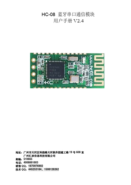
HC-08 蓝牙串口通信模块 用户手册 V2.4地址:广州市天河区科韵路天河软件园建工路19号608室广州汇承信息科技有限公司邮编:510665电话:4008881803销售QQ:1870976902版本信息软件版本:HC-08 V2.4硬件版本:V2.0发布日期2016年 07月 08日修改记录1. 更新“A T+VERSION”指令。
(2014.08.22)2. 更新“A T+BAUD”指令。
(2014.08.22)3. 增加“A T+RX”指令。
(2014.08.22)4. 增加“A T+DEFAUL T”指令。
(2014.08.22)5. 增加“A T+RESET”指令。
(2014.08.22)6. 增加“A T+ROLE”指令,取消原 34 引脚设置角色功能。
(2014.08.22)7. 增加“A T+ADDR”指令。
(2014.08.22)8. 增加“A T+MODE”指令,增加低功耗、超低功耗模式。
(2014.08.22)9. 增加“A T+RFPM”指令。
(2014.08.22)10. 增加“A T+CONT”指令。
(2014.08.22)11. 增加“A T+A VDA”指令。
(2014.08.22)12. 增加“A T+TIME”指令。
(2014.08.22)13. 增加“A T+CLEAR”指令。
(2015.07.30)产品介绍HC-08蓝牙串口通信模块是新一代的基于Bluetooth Specification V4.0 BLE蓝牙协议的数传模块。
无线工作频段为 2.4GHz ISM,调制方式是GFSK。
模块最大发射功率为4dBm,接收灵敏度-93dBm,空旷环境下和iphone4s可以实现80米超远距离通信。
模块采用邮票孔封装方式,可贴片焊接,模块大小26.9mm×13mm×2.2mm,很方便客户嵌入应用系统之内。
模块采用TI的CC2540芯片,配置256K Byte空间,支持AT 指令,用户可根据需要更改角色(主、从模式)以及串口波特率、设备名称等参数,使用灵活。
HC系列蓝牙产品用户使用指导说明书201104修订-1

e 6、关于密码的修改
r HC-06 密码的修改可以通过指令 AT+PINxxxx,但需要注意,通过指令修改成功之后,模块必须
te 彻底放电,新密码才能生效,只要彻底放电之前,旧密码还是有作用的。测试的时候,可以在
断电之后,把电源和地短接 20 秒,整个系统将会彻底放电,新密码生效。一般情况下,如果
is 外围没有彻底放电的设计的设计的话,关机半个小时也是可以彻底放电的,具体情况需要用户
根据具体情况具体分析。
g 7、主机时没有名字的,用户测试的时候不要尝试修改主机的名字,蓝牙名字的长度不要超过 20
个字符。
e 小结:HC-06 的指令比较少,操作简单,价格便宜,适合用法比较特定的用户,在此不做过
完毕,可以通信 LED2:32 脚,配对前低电平,配对完毕可以通 信为高电平 主从机指示灯用法是一样的。 注意:LED1 和 LED2 引脚外接 LED+脚。 功耗:配对中是 30~40MA 左右,波动,平均电流 是 25MA 左右。配对完毕,不论通信与否,都是 8MA,无休眠模式。该参数所有型号的蓝牙模块 都是一样的。 复位:11 脚,低电平复位,使用时可以悬空
问版本号等几个基本功能,不如 HC-03\HC-05 的灵活和指令集多,一般来说推荐用户使用
HC-03\HC-05 的蓝牙。
下面列举 HC-05 和 HC-06 出厂时的主要参数,注意区别:
HC-05
HC-06
主机与从机可以切换
主机与从机不可以切换
蓝牙名:HC-05
蓝牙名:linvor
密码:1234
图 6 是蓝牙底板的原理图,该原理图的接法可以使蓝牙模块的工作电压扩大为 3.1~6.5V, 此时通过图 6 的 J1 口,可以接入 3.3V 系统的单片机或者 5V 系统的单片机,也可以接入电脑串口。
SHENGRUN HY-40R201 Bluetooth 5.0 模块规格参数说明书
HY-40R201Copyright © 2010-2017 SHENGR All rights reserved.SHENGRUN Technologies assum this manual, Furthermore, SHEN hardware, software, and/or speci not make any commitment to upd products are not authorized for us SHENGRUN Technologies assum of intellectual property rights. The Bluetooth trademark is owneLevel:1 Bluetooth BLE 5.0 Module Specifications (40 pin)11 Nov. 2017 Version:V2.2ENGRUN Technology Co., Ltd. assumes no responsibility for any errors which HENGRUN Technologies reserves the right to specifications detailed here at any time withou o update the information contained here. SHE for use as critical components in life support d assumes no responsibility for any patents or aowned by the Bluetooth SIG Inc., USA vel: Public Informationonswhich may appear in ght to alter the hout notice and does SHENGRUN’sport devices or systems.s or authorized the useVersion HistoryCONTENTS1. DESCRIPTION (1)1-1.APPLICATIONS: (1)1-2.KEY FEATURES: (1)2. PRODUCT MODEL NUMBER: HARDWARE MODEL DESCRIPTION (2)2-1.(4 KINDS A NTENNA TYPE FOR CHOICE),(O PTION: WITH SHIELD CASE OR NO SHIELD CASE) (2)2-2:FCC ID&(IC ID/ WAIT DEFIND)P RINT F ORMAT ON THE S HIELD C ASE :(HY-40R201PC MODEL ONLY) (2)3. PCBA DIMENSION SIZE AND PICTURE (2)3-1:HY-40R201P/WMD40R201SR6P0(PCB IFAA NTENNA) (2)&HY-40R201PC/WMD40R201SR6PC(PCB IFAA NTENNA, WITH SHIELD CASE); (2)3-2:HY-40R201I/WMD40R201SR6I0(IPEX RF CONNECTOR TERMINAL) (3)&HY-40R201IC/WMD40R201SR6IC(IPEX RF CONNECTOR WITH SHIELD CASE ) (3)3-3:HY-40R201W/WMD40R201SR6W0(M ETAL W IRE A NTENNA)(1/4Λ HALF WAVE DIPOLE)_ (3)&HY-40R201WC/WMD40R201SR6WC(M ETAL W IRE A NTENNA, WITH SHIELD CASE); (3)3-4:HY-40R201C/WMD40R201SR6C0(C ERAMIC A NTENNA) (3)&HY-40R201CC/WMD40R201SR6CC(C ERAMIC A NTENNA, WITH SHIELD CASE); (3)4.APPLICATION NOTE: (4)5. PINOUT AND GPIOFUNCTION DESCRIPTION (5)6. ELECTRICAL CHARACTERISTICS (6)6-1.R ADIO PERFORMANCE & CURRENT CONSUMPTION (7)6-2.A BSOLUTE M AXIMUM R ATINGS (7)6-3.ESD R ATINGS (7)6-4.R ECOMMENDED O PERATING C ONDITIONS (8)6-5.GPIODC C HARACTERISTICS (8)6-6.T IMING R EQUIREMENTS (8)6-7.S WITCHING C HARACTERISTICS (9)7. BLOCK DIAGRAM (9)8. FUNCTIONAL BLOCK DIAGRAM (9)9. WORKING MODE SCHEMATIC (10)10. RECOMMEND REFLOW PROFILE( LEADLESS SOLDER CREAM: SN 96.5%, AG 3%, CU 0.5%) (10)11.HY-40R201PC/WMD40R201SR6PC MODULE FCC/INDUSTRY CANADA STATEMENT (11)12.CONTACT US (13)1. DescriptionHY-40R201 Bluetooth low energy single mode module is a single mode device targeted for low power sensors and accessories.HY-40R201 offers all Bluetooth low energy features: radio, stack, profiles and application space for customer applications. The module also provides flexible hardware interfaces to connect sensors. HY-40R201 can be powered directly with a standard 3V coin cell batteries or pair of AAA batteries. in lowest power shutdown mode it consumes only 0.15uA and will wake up in few microseconds. HY-40R201 transmission distance of 100 meter or more. (At face to face, free space, 1.2 Meter high from Ground for testing).Bluetooth IC:TTC2640R2 6*6*0.9mm 48pin IC,Used TI CC2640R2 die chip1-1.APPLICATIONS:Heart rate sensorsPedometersWatchesBlood pressure and glucose metersWeight scalesKey fobsHouseholds sensors and collector devicesSecurity tagsWireless keys (keyless go)Proximity sensorsHID keyboards and miceIndoor GPS broadcasting devices1-2.KEY FEATURES:Bluetooth v.5.0 single mode compliantSupports master,slaveand master/slave modesIntegrated Bluetooth low energy stackGAP, GATT, L2CAP, SMP Bluetooth low energy profilesPre-certified RF regurations for BQB BLE 5.0, CE ETSI RED, FCC, IC(Canada), (FCC and IC certified only for HY-40R201PC PCB antenna with shield case model);Another can Compliance for worldwide RF Regulations.Transmit power :+5 dBm typicalReceiver sensitivity: -97dBm typicalUltra low current consumption :Shutdown. No clocks running, no retention: 150 nA(Typical) Programmable ARM Cortex-M3 processor for embedding full applications2. Product model Number: Hardware Model Description2-1. (4 kinds Antenna type for choice) ,(Option: with shield case or no shield case)2-2: FCC ID &( IC ID/ wait defind) Print Format on the Shield Case :( HY-40R201PC model only)3. PCBA dimension size and picture3-1: HY-40R201P / WMD40R201SR6P0( PCB IFAAntenna)&HY-40R201PC / WMD40R201SR6PC (PCB IFA Antenna, with shield case);(PCBA dimension size : ( 25.16*15.22*2.0/2.6 mm ).Word Type: CalibriDirection: Horizon23267-HY40R201PC3-2:HY-40R201I / WMD40R201SR6I0(IPEX RF connector terminal)&HY-40R201IC / WMD40R201SR6IC (IPEX RF connector with shield case ) (PCBA dimension size : 25.16*15.22*2.6 mm).3-3: HY-40R201W / WMD40R201SR6W0( Metal WireAntenna)(1/4λ half wave dipole)_ &HY-40R201WC / WMD40R201SR6WC ( Metal Wire Antenna, with shield case) ; (PCBA dimension size : 23.2*15.22*2.0/2.6 mm).3-4: HY-40R201C / WMD40R201SR6C0( CeramicAntenna)&HY-40R201CC / WMD40R201SR6CC (Ceramic Antenna, with shield case) ;(PCBA dimension size : 25.16 * 15.22 * 2.0/2.6 mm ).4.Application Note:4-1.Attention to the electrostatic protection, prevent the soldering ironand the equipment grounding bad; And the workbench, working environment,packaging materials and from the human bodyTouch with static electricity,etc., destroy IC and software be fly; Manual welding module solder irontemperature, should pay attention to avoid the PCB copper strippingoff;Soldering iron strictlyGrounding requirements, eliminating ironpower failure module;4-2.Attention to avoid the overall motherboard power supply circuit of badwelding connected to short circuit or open circuit, causing the bluetoothchip, abnormal voltage,Thesoftwarewill fly and problems of IC was damaged.4-3.When programming firm ware , the VDDS supply voltage must in DC 2.4~3.3V, To avoid programming has not completely, and abnormal status occur..4-4. Use the module in the production and the transport process, pleaseinsure module’scomponent protection, prevent the precision parts on the moduleDamaged (welding furnace exit and assembly, testing, delivery process,suggest using collision buffer material, not collide with each other)4-5. The module for the humidity sensitive components, if used in SMT reflowsoldering operations, please strictly follow the IPC/JEDECJ - STD - 020regulation, completes the drying dehumidifying , and for this module hassecond processing work after placed in the functional test environment,the humidity of the chip is no guarantee that in a certain ratio, the honoredguest please understand;(The attention note show in below Fig.)4-6. The diagram (show in below Fig.) of the module application on external filter parts, whenneed, please design in the mainboard, the parts parameter can depend on the actual need to changes.4-7.Assembly recommendation 1: Underneath the module antenna and RF circuit on themainboardPCB copper need to clearance, and place close to the main board edge, as show in below Fig. The antenna can't be near aroundmetal parts and prevent material existence of electromagnetic radiation , Can affect the manipulation of the distance.4-8. Assembly recommendation 2: Signal trace and power supply trace, don't cross layout, as show in below Fig.To avoid crosstalk, affect the receiving sensitivity.5. Pinout and GPIOfunction Description Function Description GPIO, Sensor Controller (I:4mA max) GPIO, Sensor Controller (I:4mA max) The must pay attention to:Around must be clear, Module antenna should be on the electromagnetic surround antenna area.6. Electrical Characteristics(Test condition: With Ta = 25 ℃, VDD =3.0V with internal DC-DC converter, standardmeasure:1Mbps GFSKmodulation ,FRF = 2440MHz Bluetooth Low energy mode.)6-1.Radio performance & current consumption(Test condition:With Ta = 25 ℃, VDD =3.0V, with internal DC-DC converter, standardmeasure:1Mbps GFSKmodulation ,FRF = 2440MHz Bluetooth Low energy mode.) Modulation Mode: GFSKFrequency range: 2402~2480MHZ (2.4GHz ISM band)Transmit power setting Range: -21 ~ +5 dBm typical ( differential mode o/p point characteristics ; programmable by software)Receiver sensitivity: -97dBm typical( differential mode o/p point characteristics)Pre-certified RF regurations for BQB BLE 4.2/5.0, CE ETSI RED, FCC, IC(Canada), (FCC and IC only for HY-40R201PC PCB antenna with shield case model);Another can Compliance for worldwide RF Regulations.Ultra low current consumptionTransmit:6.1mA(typical)(O/P Power setting :0dBm)Transmit:9.1mA(typical)(O/P Power setting :5dBm)Receive(high gain setting): 6.1 mA(typical)Idle. Supply Systems and RAM powered:550uA(Typical)Standby. With Cache, RTC, CPU, RAM and partial registerretention. XOSC_LF: 3.0 uA(Typical)Shutdown. No clocks running, no retention: 150 nA(Typical)6-2. Absolute Maximum RatingsNote: These are absolute maximum ratings beyond which the module can be permanently damaged, these are not Maximum operating conditions, the maximum recommended operating conditions are6-3. ESD Ratings6-4. Recommended Operating ConditionsSupply voltage noise should be less than 10mVpp. Excessive noise at the supply voltage will reduce(2).When programming firm ware , the VDD supply voltage must in DC 2.4~3.3V,To avoid programming has not completely, or abnormal status occur..(3).For smaller coin cell batteries, with high worst-case end-of-life equivalent source resistance, a 22-μF VDDS input capacitor must be used to ensure compliance with this slew rate(6-6 timing req.). 6-5.GPIODC Characteristics6-6. Timing Requirements(1) For smaller coin cell batteries, with high worst-case end-of-life equivalent source resistance, a 22-μF VDDS input capacitor must be used to ensure compliance with this slew rate.(2) Applications using RCOSC_LF as sleep timer must also consider the drift in frequency caused bya change in temperature .6-7. Switching Characteristics7. Block Diagram8. Functional Block Diagram9. Working mode schematic Array10. Recommend Reflow Profile( Leadless solder cream: Sn 96.5%, Ag 3%, Cu 0.5%)Reflow Curve Classification11.HY-40R201PC/WMD40R201SR6PC Module FCC/Industry Canada Statement(to be placed on End Products)Federal Communications Commission (FCC) StatementFCC Statements(OEM) Integrator has to assure compliance of the entire end-product incl. the integrated RF Module. For 15 B (§15.107 and if applicable §15.109) compliance, the host manufacturer is required to show compliance with 15 while the module is installed and operating.Furthermore the module should be transmitting and the evaluation should confirm that the module's intentional emissions (15C) are compliant (fundamental / out-of-band). Finally the integrator has to apply the appropriate equipment authorization (e.g. Verification) for the new host device per definition in §15.101.Integrator is reminded to assure that these installation instructions will not be made available to the end-user of the final host device.The final host device, into which this RF Module is integrated" has to be labeled with an auxiliary label stating the FCC ID of the RF Module, such as "Contains FCC ID: 2ADXE-HY-40R201PC "This device complies with part 15 of the FCC rules. Operation is subject to the following two conditions:(1)this device may not cause harmful interference, and(2)this device must accept any interference received, including interference that may cause undesired operation.""Changes or modifications to this unit not expressly approved by the party responsible for compliance could void the user’s authority to operate the equipment."the Integrator will be responsible to satisfy SAR/ RF Exposure requirements, when the module integrated into the host device.Module statementThe single-modular transmitter is a self-contained, physically delineated, component for which compliance can be demonstrated independent of the host operating conditions, and which complies with all eight requirements of § 15.212(a)(1) as summarized below.1) The radio elements have the radio frequency circuitry shielded.2) The module has buffered modulation/data inputs to ensure that the device will complywith Part 15 requirements with any type of input signal.3) The module contains power supply regulation on the module.4) The module contains a permanently attached antenna.5) The module demonstrates compliance in a stand-alone configuration.6) The module is labeled with its permanently affixed FCC ID label.7) The module complies with all specific rules applicable to the transmitter, including all the conditions provided in the integration instructions by the grantee.8) The module complies with RF exposure requirements.NOTE: This equipment has been tested and found to comply with the limits for aClass B digital device, pursuant to part 15 of the FCC Rules. These limits aredesigned to provide reasonable protection against harmful interference in aresidential installation. This equipment generates uses and can radiate radiofrequency energy and, if not installed and used in accordance with the instructions,may cause harmful interference to radio communications. However, there is noguarantee that interference will not occur in a particular installation. If thisequipment does cause harmful interference to radio or television reception, whichcan be determined by turning the equipment off and on, the user is encouraged totry to correct the interference by one or more of the following measures:- Reorient or relocate the receiving antenna.- Increase the separation between the equipment and receiver.-Connect the equipment into an outlet on a circuit different from that to which thereceiver is connected.-Consult the dealer or an experienced radio/TV technician for helpIndustry Canada (IC) Statement This device complies with Indus Operation is subject to the follo (1) This device may not cause i (2) This device must accept any operation of the device.Canada, avisd’Industry Canada (IC)Le présentappareilestconforme exempts de licence.L'exploitationestautorisée aux d (1) l'appareil ne doit pas produi (2) l'utilisateur de l'appareildoit lebrouillageest susceptible d'en com 12.Contact UsShenZhenShengRun Technology Co Phone: +86-755-86233846 Fax: +86-755-82970906Official Website: Alibaba Website:http://shop143943E-mail: **********************Address: Room 602,B Block of LongNanshan District, Shenzhen, GuangIndustry Canada licence‐exempt RSS standar followingtwo conditions: ause interference, and pt any interference,including interference that a (IC)orme aux CNR d'Industrie Canada applicables aux deux conditions suivantes: roduire de brouillage, et ldoit accepter tout brouillageradioélectriquesu n comp gy Co.,Ltd. om Longjing Jingu Hi-tech Pioneer Park, Longzhu uangdong, China.andard(s). that may cause undesired cables aux appareils radio uesubi, mêmesi ngzhu 4th Road, Xili Town,。
汇承hc-05蓝牙模块用户手册(中文版)

HC-05蓝牙串口通信模块用户手册V2.1Rev22.1~2016/2/222016/2/22~2.0 2.1DRAWN BY:Ling Xin MODEL:HC-05(主从一体) CHECKED BY:Eric Huang描述:BC04外置8M Flash模块APPD.BY:SimonMokUART(默认)9600蓝牙模块HC-05、HC-06、HC-08无线模块HC-11、HC-12带底板模块参数架HC-USB-PPIN(默认)1234USB转TTL接口HC-05-USB、HC-06-USB HC-11-USBMODE(默认)从机新版模块带有蓝牙指示灯(靠近模块第1脚)。
模块的22脚LED_CON是指示灯控制脚,该脚接地,蓝牙指示灯关闭;该脚悬空,蓝牙指示灯亮。
如果要调整灯的亮度,可以在该脚接一个1K~47K的电阻到模块的31脚LED1,电阻越小,灯越亮。
贴片炉温参考建议首次大批量贴片生产的厂家,先过炉20~30片模块,检查炉温是否合适建议贴片锅炉炉温不得超过参考图温度,二次贴片降低5度左右,夏天可以再适当降低温度供电电压3.1~4.2V工作电流不大于50mA(以实测为准)尺寸大小27mm*13mm*2mm存储温度:-40℃至+85℃,工作温度:-25℃至+75℃数字2.4GHz无线收发射内置2.4GHz天线,用户无需调试天线蓝牙2.0,2Mbps空中波特率CSR BC04蓝牙芯片技术支持Android、WINXP、WIN7数据收发通过UART串口收发HC-05封装下载:/downloadDis.asp?id=15安卓串口助手APP下载:/downloadDis.asp?id=49 PC串口助手下载:/downloadDis.asp?id=44注:蓝牙模块的PIN2:UART-RXD不带上拉,如果单片机TXD无上拉能力的话需要在模块的UART-RXD脚上接个上拉电阻,这个很容易被用户忽略。
因为内容较长,请参考公司网站下载中心提供的文档HC-05AT指令集下载:/downloadDis.asp?id=64。
亿佰特 E104-BT52 BLE5.0低功耗贴片型蓝牙转串口模块规格书说明书

E104-BT52/E104-BT52X产品规格书DA14531BLE5.0低功耗贴片型蓝牙转串口模块目录第一章概述 (3)1.1简介 (3)1.3应用场景 (4)第二章规格参数 (4)2.1极限参数 (4)2.2工作参数 (4)第三章机械尺寸与引脚定义 (6)第四章基本应用 (8)4.1推荐电路 (8)第五章功能说明 (9)5.1角色说明 (9)5.2电源模式 (10)5.3数据传输模式 (10)5.4MAC地址绑定 (11)5.5广播 (11)5.6配置 (12)5.7数据指示 (12)5.8UUID说明 (13)5.9状态或事件打印 (13)第六章AT指令 (14)6.1指令说明 (14)6.2错误代码 (14)6.3状态打印 (14)6.4指令表 (14)第七章快速使用 (28)7.1配置模式快速使用指南 (28)7.2数据传输 (30)第八章常见问题 (32)8.1传输距离不理想 (32)8.2模块易损坏 (32)8.3误码率太高 (33)第九章焊接作业指导 (34)9.1回流焊温度 (34)9.2回流焊曲线图 (34)第十章相关型号 (35)第十一章批量包装方式 (36)修订历史 (37)关于我们 (37)第一章概述1.1简介E104-BT52/E104-BT52X是一款基于蓝牙协议5.0版本的串口转BLE蓝牙主从一体模块,体积小、功耗低,工作在2.4GHz 频段。
E104-BT52/E104-BT52X模块是成都亿佰特电子科技有限公司基于dialog的DA14531芯片研发,该模块使用通用的AT指令设置参数,操作简单快捷。
模块仅支持蓝牙主机、从机和观察者模式,模块在功能上支持低功耗广播、数据透传、空中配置。
模块可广泛应用于智能穿戴、家庭自动化、家庭安防、个人保健、智能家电、配饰与遥控器、汽车、照明、工业互联网、智能数据采集、智能控制等领域。
最大支持波特率460800bps的数据传输。
HC-05模块资料
HC-05模块资料
简介
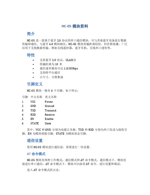
HC-05是一款基于蓝牙2.0协议的串口通信模块,可与其他蓝牙设备进行数据传输和通信。
与蓝牙4.0模块相比,HC-05模块传输距离较短,但价格低廉,广泛应用于无线数据传输,例如无线遥控器,蓝牙耳机,无线串口透传等。
特性
•支持蓝牙2.0协议,CLASS 2
•传输距离为10米
•通信速率最高可达115200bps
•支持跨平台通信
•小尺寸,方便集成
引脚定义
HC-05模块一般有6个引脚,如下所示:
引脚中文名称英文名称
1 VCC Power
2 GND Ground
3 TXD Transmit
4 RXD Receive
5 EN Enable
6 STATE State
其中,VCC和GND分别为电源正负极,TXD和RXD分别为串口发送与接收引脚,EN为模块使能引脚,STATE为模块状态引脚。
通信设置
使用HC-05模块进行通信前,需要进行一些设置。
AT命令模式
HC-05模块有两种工作模式:通信模式和AT命令模式。
通信模式下,模块直接进行串口通信;AT命令模式下,模块可以接受AT命令,进行设置和调试。
进入AT命令模式的方法:
•在上电过程中,在模块LED灯开始闪烁前,按住模块按键不放。
•上电后,可以通过发送。
HC-04蓝牙串口通信模块用户手册 V1.0说明书

HC-04蓝牙串口通信模块用户手册V1.0软件版本:HC-04V1.0硬件版本:V1.0发布日期2020年03月16日修改记录HC-04蓝牙串口通信模块是新一代的基于V2.1(SPP)经典蓝牙协议和V4.0(BLE)蓝牙协议的双模数传模块。
无线工作频段为2.4GHz ISM,调制方式是GFSK。
模块发射功率为3dBm,接收灵敏度为-90dBm。
模块采用邮票孔封装方式,可贴片焊接,模块大小18.5mm×13mm×2.2mm,很方便客户嵌入应用系统之内。
产品尺寸管脚定义HC-04模块适用于贴片焊接,共有16个引脚,板载PCB天线,引脚具体定义如下表:引脚定义I/O方向说明1GND模块公共地2VCC输入电源脚,要求直流3.3V电源,供电电流不小于200mA 3TXD输出UART输出口,3.3V TTL电平4RXD输入,弱上拉UART输入口,3.3V TTL电平5NC悬空6NC悬空7NC悬空8NC悬空9PB1输出模块连线指示,连线前为高电平,连线后输出低电平。
10PB2输入,下拉AT指令设置脚(注②)11PB3输出模块指示灯输出脚(注①)12PB4输入,弱上拉AT指令设置脚(注③)13NC悬空14NC悬空15NC悬空16RST输入,弱上拉模块复位脚,要求不小于100ms的低电平进行复位注①:模块指示灯输出脚,高电平输出,接LED时请串接电阻。
连线前,LED快闪。
连线后,LED常亮。
注②:输入脚,内部下拉。
在连线状态下,此脚接高电平,可以进入AT指令设置模式;此脚接低电平(或者悬空),返回到串口透传模式。
注③:输入脚,内部弱上拉。
在连线状态下,此脚接低电平,可以进入AT指令设置模式;此脚接高电平(或者悬空),返回到串口透传模式。
电气特性:参数测试条件参考值工作电压-DC3.0V~3.6V工作电流BLE未连接20mA~60mA变化已连接约22mA SPP未连接20mA~60mA变化已连接约30mA模块参数设置AT指令AT指令用来设置模块的参数,模块在未连线状态下可以进行AT指令操作,连线后进入串口透传模式。
- 1、下载文档前请自行甄别文档内容的完整性,平台不提供额外的编辑、内容补充、找答案等附加服务。
- 2、"仅部分预览"的文档,不可在线预览部分如存在完整性等问题,可反馈申请退款(可完整预览的文档不适用该条件!)。
- 3、如文档侵犯您的权益,请联系客服反馈,我们会尽快为您处理(人工客服工作时间:9:00-18:30)。
HC-42蓝牙5.0BLE串口模块用户手册
目录
一.模块介绍
1.1特点简介 (3)
1.2基本参数 (3)
1.3电气特性 (3)
1.4系列产品 (4)
二.连接通讯说明
2.1模块工作原理简单介绍 (4)
2.2模块MCU等设备的连接通讯 (4)
2.3模块与手机的连接通讯 (5)
三.快速测试
3.1参数架与模块连接 (5)
3.2通讯测试 (5)
四.开发利用
4.1模块尺寸和引脚定义 (6)
4.2嵌入方式 (7)
4.3参考连接电路 (8)
五.AT指令
5.1模块参数设置AT指令 (9)
5.2指令集总 (9)
5.3指令说明 (10)
六.关于汇承
6.1公司简介 (14)
发布日期:2018-02-08
1.1特点简介
HC-42蓝牙串口通信模块是新一代的基于Bluetooth Specification V5.0BLE 蓝牙协议的数传模块。
无线工作频段为2.4GHz ISM ,调制方式是GFSK 。
模块最大发射功率为4dBm ,接收灵敏度-96dBm 。
模块大小26.9mm×13mm×2.0mm ,集成了邮票孔封装,可以贴片工艺,很方便嵌入应用系统之内。
1.2基本参数
参数名称参数值参数名称参数值型号HC-42模块尺寸26.9X13mm 工作频段 2.4G 空中速率1Mbps/2Mbps 工作电压 1.8~3.6V 天线接口内置PCB 天线
工作电流参照1.3表中所述
停机电流0.3μA 通讯接口UART
接收灵敏度-96dBm@1Mbps 通信电平 1.8~3.6V ,与工作电压一致
工作湿度10%~90%发射功率-40~4dBm
存储温度-40℃~+85℃参考距离
40m/2Mbps (蓝牙5.0)
工作温度
-25℃~+75℃
1.3电气特性
数值
备注
电压特性
1.8V~3.6V 若使用纽扣电池,必须保证电压在
2.5V 以上
参考电流(不包括LED )
1.23mA/1.22mA
全速广播/全速连接
75μA/65uA 低功耗广播/低功耗连接(工作电流随广播间隔变化)
0.3μA
停机状态注:以上电流数据是基于气温25℃、工作电压3.3V 、出厂默认配置时测得,实际使用可能存在误差。
2.1模块工作原理简单介绍
如上图所示,HC-42模块用于代替全双工通信时的物理连线。
左边的设备向模块发送串口数据,模块的RXD
收到串口数据后,自动将数据以无线电波的方式发送到空中。
右边的模块能自动接收到,并从TXD还原最初左边设备所发的串口数据。
从右到左也是一样的。
注:本版本不支持主机设置,后续版本才支持主机。
模块与单片机MCU等设备的连接
MCU连接时,串口交叉连接即可(模块的RXD接
MCU连接时,如果MCU高电平阈值不高于3V的话,可在模块的
TXD,模块的TXD直接连接MCU的RXD,无需串接电阻。
如果的话,必须加电平转换电路再进行连接。
1.8~3.6V,不能直接接5V电源。
5V的电源必须通过LDO
2.3模块与手机的连接
HC-42支持与Android4.3及以上版本的手持设备连接通讯,通信测试需使用BLE安卓串口助手连接。
HC-42支持与iPhone4S及以上版本的手持设备连接通讯,通信测试需在APP Store下载安装Lightblue蓝牙助手软件连接(也可以使用其他支持BLE蓝牙的串口软件)。
3.1参数架与模块连接
将蓝牙模块HC-42放入参数架HC-USB-P中(如图),直接插入PC的USB接口就可以对模块进行调试。
3.2通讯测试
请前往广州汇承官方网址下载HID串口小助手
另外,关于HID小助手的下载途径还有以下两种:
(1)扫描HID参数架上的二维码
(2)打开HID参数架虚拟U盘上的链接
发送指令AT,返回OK即为通讯正常。
可以参照AT指令表更改模块的工作参数。
注:后续版本HID才支持HC-42参数设置,目前可以在发
送框输入AT指令进行测试。
4.1模块尺寸和引脚定义
引脚定义I/O方向说明
1TXD(P0.06)输出UART输出口,3.3V电平
2RXD(P0.08)输入,上拉UART输入口,3.3V电平
3P0.07无设置,请悬空
4P0.05无设置,请悬空
5P0.28输出上电后输出低电平
6SWDCLK输入仿真、烧录时钟脚,请悬空
7SWDIO输入/输出仿真、烧录数据脚,请悬空
8P0.29无设置,请悬空
9P0.30无设置,请悬空
10P0.31无设置,请悬空
11RESET输入,上拉模块复位脚,要求不小于50ms的低电平进行复位
12VCC输入电源脚,要求直流3.3V电源,供电电流不小于50mA
13GND模块公共地
14LEDCON输入模块板载指示灯LED2控制脚(注①)
15P0.12无设置,请悬空
16LED1(P0.13)输出模块外部指示灯输出脚(注②)
17LINK(P0.14)输出连接指示(未连接状态输出高电平,连接后输出低电平)18KEY+(P0.15)无设置,请悬空
19LPIN(P0.16)输入,上拉低功耗控制引脚,高电平表示“低功耗”,低电平表示“退出低功
耗”(注③)
20LPOUT(P0.17)输出模块低功耗指示(标准状态下输出低电平,低功耗状态下输出
高电平)
模块天线部分下面不能敷铜,不能走线,否则影响信号,建议天线部分底板挖空,天线尽量靠近板边。
采用邮票孔封装方式,模块尺寸和引脚定义请参考4.1。
5.1模块参数设置AT指令
1、AT指令用来设置模块的参数,模块在未连线状态下可以进行AT指令操作,连线后进入串口透传模式。
2、模块启动大约需要300ms,所以最好在模块上电或者复位完成350ms以后才进行AT指令操作。
除特殊说明外,
AT指令的参数设置立即生效。
同时,参数和功能的修改,掉电不会丢失。
3、AT指令修改成功后统一返回OK(“AT+RX、AT+VERSION”等查看信息类指令除外),不成功不返回任何信息。
5.2指令集总
序号
AT指令
(小写x表示参数)
作用默认状态备注
1AT检测串口是否正常工作
2AT+VERSION获取模块版本和官网网址
3AT+NAME=xxxx修改蓝牙名称HC-42
4AT+RFPM=xx更改无线射频功率4dBm
5AT+UART=xxxx修改串口波特率9600
6AT+AINT=xx更改广播间隔200mS
7AT+PM=x修改模块功耗模式0
8AT+SLEEP模块进入睡眠
9AT+PD模块进入停机
10AT+LEDnM=x LED指示灯工作模式
11AT+DEFAULT恢复出厂默认参数
12
13
14
15
16
17
18
19
20
21
22
23
24
25
26
注:
AT指令后面不用回车换行;如无特殊说明,本模块所有AT指令,一律不采用换行发送。
广州汇承信息科技有限公司成立于2008年9月,是无线数传领域的先行者。
十余年来始终坚持自主研发,为广大科技公司提供无线数传的解决方案。
HC系列模块远销世界各国,累计销量已达到数千万片。
以性能稳定,嵌入方便,丢包率低等优点得到各国技术专家的一致好评。
其中HC-05和HC-06蓝牙串口模块更是被称为无线数传产品的经典之作,十余年来销量一直遥遥领先,市场份额达到40%以上。
自创的邮票封装方式,现在已被行业普遍使用。
近年来,汇承通过不断创新,相继研发了多种工作制式的无线串口模块,形成了以蓝牙2.0、蓝牙4.0BLE、无线433MHz、WIFI为主的四大串口系列产品,以及相配套的支持产品。
我们一直在路上,不忘初心。
方得始终,汇承人始终坚守“汇聚信息,承载梦想”的理念,尽自己所能,尽一切所能,为无线数传领域,为社会做贡献!
本规格书所属权归广州汇承信息科技有限公司所有,本公司保留未经通知随时更新本产品使用手册的最终解释权和修改权!。