CSR57F68蓝牙模块F-3088版本V6.0规格书
RWD68 Universal Controller 的商品说明书

CE2N3343en3343RWD68Universal ControllerRWD68For comfort control in HVAC&R-SystemsStandalone electronic universal controller with P or PI response Operating voltage in accordance to type AC 24 VControl application selectable via Application Number Active input scale can be selectableLimit and direction of the output scale is able to be freely assigned Two universal inputs for Ni 1000, Pt 1000 temperature sensors and DC 0…10 V signalsUnit can be set as °C, °F, % or no specified unitOne modulating output with DC 0…10 V signal output, direct or reverse action One two-position output, direct or reverse action One digital input for day/night changeoverEntering or changing of all data via operating buttons on the controller, possi-ble without additional toolsPC connection for downloading canned applications via the software toolUseThe universal controllers are intended for Heating, Ventilating, Air-Conditioning and Refrigeration in comfort control plants. It can be mounted in a control panel or in theARG62.21/ARG62.22 housing on ducts, walls and in plant rooms.HVAC&R ApplicationMeasurement and control of temperature, relative humidity, absolute humidity, en-thalpy, pressure differential, volumetric airflow and indoor air quality. The input scalecan be set from –100 units to 8,000 units. The start and end points of output voltagecan be any value between DC 0 V to DC 10 V.Functions SummaryControllerStand-alone controller with one direct or reverse acting DC 0…10 V output and one2-position (ON/OFF) output with dependent and independent adjustment on eachsequence for direct - or reverse acting. Adjustable parameters including proportionalband and integral action time.Auxiliary selectable functionUniversal input X2 for one of the following functions:PI limiter function (absolute and relative)Remote setpoint functionCascade control functionSetpoint compensationWinter/summer operationMaximum priorityDigital input D1 for setpoint changeover day/nightType summaryInputs Outputs Type ReferenceUniversal Digital Analog Digital2 1 1 1 RWD68AccessoriesName TypeProtective small enclosure for wall mounting ARG62.21Protective big enclosure for wall mounting ARG62.22Software Tool S3341A031EN0 Equipment combinationsThe following Siemens units can be connected to RWD68 universal controller.Units Data sheet no.Sensor with LG-Ni 1000 temperature sensing element 17… to 19…Sensor with Pt 1000 temperature sensing element 1846Sensor with DC 0…10 V measuring signal 17… to 19…Room temperature sensor with setpoint adjuster QAA251721 / 1748or QAA25/APRemote setpoint adjusters FZA21.11 and FZA61.11 19…Air damper actuators with DC 0…10 V input 46…Valve actuators with DC 0…10 V input 45…Control valves 46…Signal converter SEM 61.4 for current valve control 51…Various signal converters 34…2/123/12Other combinations with third-party units are possible, provided the input and output specifications match the RWD68.A software tool for controller application selection and parameter adjustment is avail-able. It is a user-friendly Windows® 95 (or above) based software tool which provides you a printout of the controller settings.Functions The RWD68 is a stand-alone universal controller which performs both primary and auxiliary control functions. The respective mode is defined by entering the correspond-ing configuration and setting parameters via the push buttons on the controller or the software tool.The RWD68 controller can be programmed as follows: One sequence: Q1reverse or direct acting Two sequence: Y1 and Q1 reverse and direct acting orY1 and Q1 reverse and reverse acting (Independent and dependent control loop) orY1 and Q1direct and direct acting (Independent and dependent control loop)LoadReverse Acting Sequence (Application No.: 10-19)Direct Acting Sequences (Application No.: 80-89)O u p t u tO u p t u tReverse and Direct Acting Sequences (Application No.: 40-49)Reverse and Direct Acting Sequences (Application No.: 50-59)O u t p u tLoadO u t p u t2 Reverse Acting Sequences (Dependent control loop) (Application No.: 20-29) 2 Direct Acting Sequences (Dependent control loop) (Application No.: 60-69)Software ToolController typeMain functionsReverse and/or Direct ActingReverse and Reverse Acting or Direct and Direct Acting4/12O u p t u tO u p t u t2 Reverse Acting Sequences(Independent control loop) (Application No.: 30-39)2 Direct Acting Sequences (Independent control loop) (Application No.: 70-79)The universal input X1 is used as the primary input for a LG-Ni 1000 temperature sen-sor, a Pt 1000 temperature sensor or a DC 0…10 V active input.The universal input X2 is used as the secondary input for a LG-Ni 1000 temperature sensor, a Pt 1000 temperature sensor, an active/passive remote setpoint transmitter or a DC 0…10 V active input.The digital input D1 is used to select the day/night changeover. Changeover occurs via potential-free contacts between D1 and M.The output Y1 can be configured for either reverse or direct acting.The modulating voltage output (Y1) controls devices requiring a DC 0…10 V signal. The output Q1 can be configured for either reverse or direct acting control. Ventilating plant with temperature controlX1 Room temperature Q1 Heating, reverse action Y1Cooling, direct actionOne of the following auxiliary functions can be selected: PI limiter function (absolute and relative) Remote setpoint function Cascade control function Setpoint compensation Winter/summer operation Maximum priorityAdditionally, the day and night operation mode is available.The limiter function with PI control enables abso-lute(or relative) maximum or minimum limitation of the supply air temperature (X2).When the value drops below or exceeds the limiter setpoint, the limiter function controls and takes priority over the main setpoint.Universal input X1 Universal input X2Digital input D1 Analog output Y1 Digital output Q1 ExampleAuxiliary functionsPI limiter function5/12A remote setpoint transmitter (FZA21.11, QAA25 or QAA25/AP), connected to X2 and configured ac-cordingly, enables setpoint adjustment.Active measurement from DC 0…10 V correspond-ing adjustable range from –100 to 8000Passive measurement from 0…1000 correspond-ing adjustable range from –100 to 8000X2 Supply air temperature sensorYou can select the PI/PI room/supply air tempera-ture cascade control . In this case, the virtual PI room temperature controller determines the setpoint within the limiter setpoints for the PI supply air tem-perature controller.Maximum priority, coolingIf the value (DC 0…10 V) of the input X2 is greater than the calculated output of the cooling sequence, the output will use the X2 input value as output value. This is active even when the controller is working with the heating sequence.The temperature setpoint X1 is shifted by the tem-perature as measured at sensor X2.Configuration of the RWD68 defines the influence on setpoint X1.The example shows the room air temperature set-point as controlled by the outside temperature.A digital switch or anlog input between terminals X2 and M can be used to implement winter/summerchangeover.Digital changeoverWhen the contact is closed, summer operation is selected. Reverse acting output is set to direct ac-tion (cooling).Analog changeoverWhen the X2 input exceeds the setpoint, summer operation is selected. Reverse acting output is set to direct action (cooling).Note: The reverse acting output changeover occurs in Y1 only for application number 36, 37, 56 and 57, and in Q1 only for 16, 17, 46 and 47Remote setpointCascade controlMaximum prioritySetpoint compensationWinter/summer operation6/12A contact between terminals D1 and M can be used to implement setpoint changeover for day/night operation.When the contact is open, the setpoints for day operation are selected.When the contact is closed, the setpoints for night operation are selected.During the night mode, the following auxiliary func-tions are disabled: remote setpoint, abso-lute/relative limiter, setpoint compensation and maximum priority.Mechanical design The RWD68 universal controller is compact unit as per DIN 43 880 Gr. 1 requirements. A protective housing is used to protect the controller when mounted outside a control panel, such as on ducts, walls and in plant rooms. Furthermore, the protective housing prevents inadvertent contact with voltage supplying parts such as the connecting termi-nals.The RWD68 clips into the protective housing.The cable entries are located at the top and the bottom of the protective housing. The front has an opening for the LCD display and the programming buttons.The RWD68 universal controller can be mounted as follows: In a standard electrical control cabinet as per DIN 43 880 Wall mounted in a protective housingFront mounting with standard available installation elementsPlug-in screw terminalsThe RWD68 is operated by the buttons on the controller front. Additional tools are notnecessary. A 9-pin port is provided for optional programming via the software tool.The LCD shows the following information for normal operation: Current operating values (maximum 4 digits) Current setpoints (day/night) Applicationnumber Output voltage valueControl sequencing diagram Auxiliary input valueSelected auxiliaryfunctionThe controller has three operating buttons for the following functions: Day/night setpointHousingProtective housing ARG62.21/ARG62.22Mounting options TerminalsOperating and display elementsLCDOperating buttons7/12To configure the controller, follow the instructions supplied with the controller.Engineering notes Use this controller only for applications as described in the description on the title page (bold print) and the section "Use". Additionally, observe all conditions and restrictions imposed in this section and in "Technical data".The sections marked with a warning symbol contain technical safety requirements and restrictions. Observe all of these warnings as they directly relate to the protection of person and equipment.Installation notesThe RWD68 controllers can be mounted as follows: Observe all local installation and mounting regulations. A On a top hat rail (EN60715, 35 × 7.5) at least 120 mm long B Wall mounted with 2 screwsCFront mounted using standard elements, e.g. 1 × top hat rail 150 mm long2 x hexagonal placeholders 50 mm washers and screwsDIn the ARG62.21/ARG62.22 protective housingStandard cables can be used for the controller. However, when mounting in an envi-ronment greatly exposed to EMI, use only shielded cables. The RWD68 is designed for AC 24 V operating voltage.The low voltage must comply with the requirements for safety extra-low voltage (SELV) as per EN 60730.Use safety insulating transformers with double insulation as per EN 60742; they must be designed for 100 % on-time.When using several transformers in one system, the connection terminals G0 must be galvanically connected.Supplying voltages above AC 24 V to low voltage connections may damage or destroy the controller or any other connected devices. Additionally, connections to voltagesexceeding AC 42 V endanger personal safety.ConfigurationIntended useElectrical installation8/12Warning!No internal line protection for supply lines to external consumers. Risk of fire and injury due to short-circuits!Adapt the line diameters as per local regulations to the rated value of the installed overcurrent protection device.The power supply lines must have an external circuit breaker with a rated current of no more than 10 A.Commissioning notesA booklet is supplied with the RWD68 controller for commissioning. Observe the following:The controller must be configured for plant-specific operation using standard applica-tion number.Plant specific fine tuning can be performed if required (refer to the commissioning booklet).Power supply to the controller and the connected devices must be guaranteed Values and settings entered remain available even on power failure.Disposal The devices are considered electronics devices for disposal in terms of European Di-rective 2012/19/EU and may not be disposed of as domestic waste.Dispose of the device via the channels provided for this purpose.Comply with all local and currently applicable lawsand regulations.9/12Technical dataOperating voltageSafety extra-low voltage (SELV) as per FrequencyAC 24 V 20 % EN 60730 50 Hz/60 HzNo internal fuse.External preliminary protection with max. C 10 A circuit breaker in the supply line required under all circumstances. RWD68 3.0 VA Actual and nominal values 4 digitsLG-Ni 1000 Pt 1000Active sensor0.5 °C 0.5 °CDepends on the setting range TransportClimatic conditions Temperature HumidityMechanical conditions IEC 60721-3-2 Class 2K3 25… 70 °C <95 % r.h. Class 2M2 OperationClimatic conditions Temperature Humidity IEC 60721-3-3 Class 3K5 0… 50 °C <95 % r.h.HousingFront and with ARG62.21 Front and with ARG62.22 IP 20 as per EN 60529 IP 30 as per EN 60529 IP 30 as per EN 60529 EU Conformity (CE) RCM ConformityCE2T3341xx *) CE2T3341en_c1 *)The product environmental declaration CE1E3343en *) contains data on environmentally compatible product design and assessments (RoHS compliance, materials composition, packaging, environmental benefit, disposal). Screw terminals for cables with min. 0.5 mm dia.max. 2 x 1.5 mm 2 or 2.5 mm 2 RWD680.2875 kgGeneral data Po w er supplyPower consumption LCDDisplay resolution for (these values do not relate to the controller accuracy)Environmental conditionsEnvironmental conditionsIP codeNorms and standards Environmental compati-bility TerminalsWeight without packaging10/12Controller measuring rangeMax. cable length for dia. 0.6 mm 50… 150 °C max. 300 m Controller measuring rangeMax. cable length for dia. 0.6 mm 20… 180 °C max. 300 mRangeMax. cable length for dia. 0.6 mm DC 0…10 V corresponding to adjustable range from –100 to 8000 (°C, °F, % or no unit)max. 300 mRangeMax. cable length for dia. 0.6 mm0…1000 corresponding to adjustable range from –100 to 8000 (°C, °F, % or no unit)max. 300 m Polling voltage for control commands (D…M) Current consumption DC 15 V 15 mA RangeMaximum current DC 0…10 V 1 m ARelay contactsVoltageMaximum ratingMinimum ratingAC 24…230 VAC 230 V, 4 A resistive, 3 A ind. (per relay terminal) DC 30 V, 4 AAC 19.2 V, 20 mA DC 5 V, 100 mA*) The documents can be downloaded from /bt/download.DiagramsD1 Digital input G, G0M Ground (G0) for signal inputs, universal inputs and analog outputs Q1 Digital output, various voltages permissible AC 24…230 V X1 Signal input (main input: LG-Ni 1000, Pt 1000 and DC 0…10 V)X2 Signal input (aux. input: LG-Ni 1000, Pt 1000, DC 0…10 V and 0…1000 or DC 0…10 V remote setpoint)Y1 Analog outputToolCommunication port for PC (9-pin plug)Analog inputs X1, X2 LG-Ni 1000 at 0 °C Pt 1000 at 0 °C Analog voltages(for measured variables in °C, % or without unit)Remote setpoints X2Digital input D1 Analog outputs Y1, Y2 Digital output Q1Internal diagram11/12Connection diagramE1 Electrical load N1 RWD68 controllers PC Personal computerQ1 Potential-free relay contacts for 2-position control S1 Time clock or switchX1 Main input (Termination G appears when X1 is an active sensor)X2 Auxiliary input or remote setpoint (Termination G appears when X2 is an active sensor) Y1Valve actuator / damper actuatorPlease note that if you use a DESKTOP computer, the TOOL signal ground is gal-vanically connected to G0 inside the controller. If the signal line of the computer is grounded to Earth, the G0 line after TOOL connection will be Earthed as well.This will change from SELV to a PELV.Note12/12DimensionsARG62.21 = 150RWD68ARG62.21 / ARG62.222001 - 2015 Siemens Switzerland Ltd Subject to change。
飞利浦 BT6600A 无线隨身喇叭 产品说明书

飛利浦無線隨身喇叭Bluetooth®與 NFC 防潑濺通話用內建麥克風16W,充電式電池BT6600A 體積小巧,音效絕佳360°宏亮音場隨心所欲調整喇叭的擺放位置。
360°音域可全方位傳遞不可思議的絕佳音效。
將喇叭放置在擴充機座即可輕鬆充電。
無論室內室外,不論晴雨,皆可使用。
超長效內建電池還可為手機充電。
震撼人心的音效•雙件式喇叭驅動器與被動反射器,給您醉人的音效表現•數位音效處理播放出生動、不失真的音樂•2 x 8W RMS 總輸出功率更為進階的功能性•藍牙無線音樂串流功能•利用 MULTIPAIR,隨心所欲在 3 台裝置間切換音樂•隨附喇叭充電底座,無比便利•在啟用 NFC 的智慧型手機上按一下,即刻進行藍牙配對•免持通話用內建麥克風專為行動生活而生•最適合在潮溼環境中使用的防潑濺設計•內建充電式鋰電池,可隨時隨地播放音樂•長達 12 小時的音樂播放•可將喇叭當成行動電源,為智慧型手機充電雙件式喇叭驅動器1.75 吋雙件式釹製喇叭驅動器呈現出自然、清晰而平衡的聲音,而兩側的被動反射器更可延伸並強化低音表現。
前後置的全音域喇叭驅動器甚至能創造出 360 度音效,因此無論喇叭面向何方,您都能無拘無束地享受到同樣出色的音質。
數位音效處理先進音效處理技術強化音效再生,精準演繹每個音符,收放自如行雲流水。
飛利浦專利數位音效處理技術將組合音響的表現推向極致,帶來清澈的音效並毫無保留地忠實呈現原音,絕不失真。
無線音樂串流藍牙屬於短距離無線通訊技術,兼具穩定與省電效果。
此技術讓您輕鬆與 iPod/iPhone/iPad 或其他具備藍牙的裝置無線連線,例如智慧型手機、平板電腦或甚至筆記型電腦。
因此您能以無線方式透過此款喇叭,盡情享受來自影片或遊戲的音樂與音效!在 3 台裝置之間切換音樂同時與 3 台智慧型裝置配對,讓您可從任何一個您想要的裝置串流音樂,免去取消配對和重新配對的麻煩。
Quectel_M26-OpenCPU_硬件设计手册_V1.0
2 综述 ...................................................................................................................................................... 11
3.5.1. 主串口............................................................................................................................. 34
本文档手册版权属于移远公司,任何人未经我公司复制转载该文档将承担法律责任。
Q n 版权所有 ©上海移远通信技术有限公司 2014,保留一切权利。 Confide Copyright © Quectel Wireless Solutions Co., Ltd. 2014
上海移远通信技术有限公司
1 / 81
如需技术支持或反馈我司技术文档中的问题,可随时登陆如下网址: /support/techsupport.aspx
l 前言
移远公司提供该文档内容用以支持其客户的产品设计。客户须按照文档中提供的规范,参数来设计其产品。
te 由于客户操作不当而造成的人身伤害或财产损失,本公司不承担任何责任。在未声明前,移远公司有权对 c l 该文档规范进行更新。 ue tia 版权申明
Q n 3.2.2. 关机 ................................................................................................................................ 26 3.2.2.1. PWRKEY 引脚关机............................................................................................ 26 e 3.2.2.2. API 函数关机...................................................................................................... 27 fid 3.2.2.3. 低压自动关机 ..................................................................................................... 27 3.2.3. 推荐的系统开关机电路 ................................................................................................... 28 3.3. 省电技术 ................................................................................................................................ 29
LSD4BT-E66 蓝牙模组说明书

LSD4BT-E66系列产品规格书Product Specification产品名称:E66标准模组(PCB天线)产品型号:LSD4BT-E66文件版本:Rev04文件修订历史序号修改日志修改人审核人文件版本修改日期1初始版本王洪阳孙香涛Rev012018-5-312更新模块通信距离,加入不同连接和广播间隔的功耗数据王洪阳孙香涛Rev022018-10-113更正模块工作参数发射状态CPU主频,区分模块在ACTIVE模式和SLEEP模式的不同TRX电流,增加更多的时间间隔下的功耗数据王洪阳孙香涛Rev032018-12-114加入模块认证信息王洪阳孙香涛Rev042019-3-1目录第1章概述 (4)1.1模块功能特点 (4)1.2应用场合 (4)第2章规格参数 (5)第3章硬件布局及接口说明 (7)3.1外形尺寸图 (7)3.2接口说明 (8)3.3模块认证 (9)第4章应用说明 (10)4.1典型应用注意事项 (10)第5章生产指导 (12)5.1生产指南 (12)5.2模块在底板位置要求 (12)5.3钢网开口设计 (12)5.4回流焊作业指导 (13)第6章产品包装 (14)6.1包装方式 (14)6.2料带尺寸 (14)6.3产品方向 (14)敬告用户 (15)第1章概述E66系列蓝牙模组是基于低功耗、高性能蓝牙SOC芯片研发的一款低功耗高性能蓝牙模组,模组采用邮票孔型接口,预留PCB天线和外置天线两种接口供您选择;模块尺寸小巧,全端口引出,方便使用,可以帮助您减少软硬件投入,轻松实现蓝牙应用的开发。
型号说明LSD4BT-E66PCB天线,型号不包括软件,若为带软件产品,请与销售沟通具体型号以及MPQ等信息1.1模块功能特点●工作电压:1.6~3.6V●设计频率:2402MHz~2480MHz●发射功率:Max9dBm●超高接收灵敏度:-93±1dBm●超远有效通讯距离:30m@0dBm1.2应用场合●智能手机以及平板电脑周边产品●无线可穿戴蓝牙设备●智能灯控,智慧家居,智慧城市第2章规格参数表2-1产品极限参数表2-2模块工作参数@25℃主要参数性能备注最小值典型值最大值工作电压(V ) 1.6 3.3 3.6电源纹波要求峰峰值30mV 以内工作温度(℃)-40/+85正常通讯工作频段(MHz)2402/2480ISM 频段信道个数/40/BLE 协议标准信道个数功耗发射状态(mA)ACTIVE /10.5/2402MHz ,0dBm@16M CPU 完全工作发射状态(mA)SLEEP / 6.58/2402MHz ,0dBm@16M CPU 只有RF 部分工作接收状态(mA)ACTIVE /10.3/2402MHz @16M CPU 完全工作接收状态(mA)SLEEP / 6.09/2402MHz @16M CPU 只有RF 部分工作睡眠状态(uA)/2/发射功率(dBm)-15/7软件可配置接收灵敏度(dBm)/-93/PER<30.8%(BER <0.1%)通信协议BLE4.0/4.2接口类型 1.27mm 间距,3边邮票孔通讯距离130m@0dBm芯片配置@0dBm1.“通信距离”受测量周边环境、空气湿度等因素影响,距离是通过手机与模块通信测出,仅作参考。
爱德发蓝牙耳机W688BT说明书

版本号Ver1.1
地 址:北京市海淀区北四环西路68号生产商:东莞市漫步者科技有限公司
厂 址:东莞松山湖高新技术产业开发区工业东路2号
北京爱德发科技有限公司商标说明:EDIFIER , 均为北京爱德发科技有限公司持有注册商标,仿冒必究。
微信扫一扫,更多信息
1 左扬声器
2 右扬声器
3 可伸缩调节的头戴8 充电接口9 状态指示灯10 ▲ 键: 上一曲
温馨提示:W688BT据PCBA设计需求采用了定制缩短款Micro USB 接口,充电时插头会有小段剩余在外,属于正常现象。
充电时间:约3小时
本耳机可同时连接两个蓝牙设备,操作方法如下:电
低电
满四、使用耳机通话1、基本通话操作
2、三方通话操作
功能取消呼叫接听来电拒接来电结束通话增大音量减小音量通话传手机通话传耳机麦克风静音取消静音语音拨号末码重拨
接听新来电挂断当前通话
接听新来电保留当前通话
拒绝新来电并继续当前通话结束当前通话切换至保留的通话结束保留通话继续当前的通话
功能
通话切换
注意:
● 耳机处于静音状态时,每10秒您会听到连续响两声‘嘟嘟’提
示音。
● 对于某些手机,按手机上的接听键接听来电时,通话会优先传 送至手机,比如iphone。
此时,您可以使用耳机的通话切换 功能或通过在手机上操作,将通话切换到耳机。
注意:
若在开机状态插入3.5音频线时,耳机会关机且蓝牙连接自动 断开,AUX in音频输入有效。
若要使用蓝牙功能,请拔出3.5音频线,并重新开机进行配对说明书/W688BT/国内/V1.1
尺寸:70x125mm 128克铜版纸双面过哑胶,黑色印刷,装钉。
DL-RXS868R超外差ASK无线接收模块说明书

DL-RXS868R深圳市骏晔科技有限公司DVER 1.0DL-RXS868R超外差ASK无线接收模块DL-RXS868R超外差无线接收模块是一款性能优越的ISM频段的接收模块,采用品牌工业级射频无线数据传送芯片,具有较高的接收灵敏度和较强的抗干扰能力,无需外加任何电路即可以做到无线信号输入到数据信号输出,用户只需要外加简单的数据解码电路(包含专用解码芯片如PT2272或MCU软件解码),即可轻易实现无线产品的开发。
特点:● 完全的单片UHF接收器件,频率范围450—950MHz ;● 接收灵敏度-109dBm 工作频率868.35MHz ;● 传输速率10kbps (FIXED) 自动调谐;● 无需手动调节 无需外接滤波器和电感;● 电源电压输入范围:3.6~5.5V;● 低电源功耗,12mA 868.35Mhz,睡眠模式下待机电流<0.1mA;● 良好的选择性和杂散辐射抑制能力,易于通过CE/FCC国际认证;● 良好的本振辐射抑制能力,可多个接收模块一起工作(即单发多收),且不会互相干扰, 一起使用不影响接收距离;● 温度范围: -40~85°C, 即使在恶劣的环境温度下也能正常工作。
Shennzhen Dreamlnk Technology Co., Ltd Tel: 0755-029369047用本模块产品前,注意以下重要声明:仔细阅读本说明文档本模块属于静电敏感产品,安装测试时请在防静电工作台上进行操作。
本模块默认使用外接天线,天线可选用导线天线或者标准的UHF 天线,具体天 线的客户请根据实际情况进行选择,如果所应用的终端产品是金属外壳,请务 必把天线安装于金属外壳之外,否则会导致射频信号严重衰减,影响有效使用距离。
金属物体及导线等应尽量远离天线。
安装模块时,附近的物体应保证跟模块保持足够的安全距离,以防短路损坏。
绝不允许任何液体物质接触到本模块,本模块应在干爽的环境中使用。
CSR蓝牙方案信息对照表
特需功能输入口 工作电压范围 预估价格范围
N 2.7 ~4.4v
N 2.7 ~4.4v
N 2.7 ~4.4v
N 2.7 ~4.4v
应用
适用于中端产品,如: 1,立体声耳机。 2,立体声迷你便携音箱。 3,汽车蓝牙套件。
适用于高端产品,如: 1,立体声耳机。 2,立体声迷你便携音箱。 3,汽车蓝牙套件。 4,大功率无线音箱。 可以实现: A,PCM信号的DSP处理。 B,RFID无线射频识别,非接触式的 自动识别,与NFC类似。 C,IOS设备可显示电池供电情况。 D,GAIA应用程序。
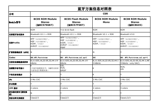
蓝牙方案信息对照表
公司 BC05 ROM Module Stereo (如BC57E687)
ROM 支持蓝牙协议版本 Bluetooth V2.1 + EDR HFP(电话通话音频流), HSP(电话功能控制), A2DP,(音乐流) AVRCP(音乐功能控制)
CSR BC05 Flash Module Stereo (如BC57F687)
6 capacitive touch sensor inputs 2.7 ~4.4v
Module型号
BC06 ROM Module Mono
ROM Bluetooth V2.1 + EDR HFP(电话通话音频流), HSP(电话功能控制), A2DP,(音乐流)
BC08 ROM Module Stereo (如BC8645)
ROM Bluetooth V3.0 HFP(电话通话音频流), HSP(电话功能控制), A2DP,(音乐流) AVRCP(音乐功能控制) Y SBC ,MP3,Faststream,AAC,aptStereo (如BC8670)
内置16M flash Bluetooth 4.0 HFP(电话通话音频流), HSP(电话功能控制), A2DP,(音乐流) AVRCP(音乐功能控制) PBAP Y SBC ,MP3,Faststream,AAC,apt-X 8,11.025,16,22.05,32,44.1,48 和96kHz(Only DAC) I2S, PCM, SPDIF Y 2 Mic CVC 2 3 colors Y Class1/2/3
CSRHarmony驱动安装和产品使用说明资料
CSR Harmony4.0蓝牙的驱动安装和产品使用说明您好!欢迎您使用本产品!让我们一起尽情享受蓝牙的无线快乐吧!首先让我们先大概了解一下本产品的特色:1.CSR V4.0蓝牙适配器采用了CSR(Cambridge SiliconRadio)公司的最新的8510芯片。
2.支持Bluetooth High Speed v3.0与low energy v4.0,并完全向下兼容v1.1/ v1.2/ v2.0/ v2.1的蓝牙设备;3.CSR蓝牙4.0芯片通过被称为Wideband Speech的技术进行音频编码解码,并进一步消除背景噪声和干扰,使无线音频的传输质量大幅提升,A2DP蓝牙立体声音频传输的音效极佳,可以媲美有线音频传输的音质;4.蓝牙4.0技术拥有极低的运行和待机功耗,同时拥有跨厂商互操作性,3毫秒低延迟,AES-128加密,无线覆盖范围增强;5.是蓝牙3.0的升级增强版本,与3.0版本相比最大的不同就是低功耗。
一:驱动部分本产品是支持免驱,即插即用的。
免驱的蓝牙适配器:意思并不是指不要驱动,而是微软公司自己在操作系统里集成了蓝牙驱动,当蓝牙适配器插上电脑后系统会自动安装微软的蓝牙驱动。
但是经我们测试,目前微软自己的蓝牙驱动仅仅能支持蓝牙键鼠协议,部分手机的蓝牙文件传输和蓝牙串口等,并不能支持蓝牙音频功能。
如果仅仅用免驱的适配器来连接蓝牙键盘或者鼠标,的确可以不用再额外安装驱动,直接插上去就可以连接、使用,但是如果需要与蓝牙耳机连接或者想体验更多的蓝牙应用,那么必须安装我们的驱动。
本驱动支持多国语言介于本驱动内容较大,有四百多MB。
Windows XP_32位/Windows vista_32位/Windows7_32位/Windows8_32位操作系统,请直接打开“Setup”文件夹,双击文件,即可开始进入驱动程序的安装。
Windows XP_64位/Windows vista_64位/Windows7_64位/Windows8_64位操作系统,请打开“X64”文件夹,进入后双击“setup”文件,即可开始驱动程序的安装。
- 1、下载文档前请自行甄别文档内容的完整性,平台不提供额外的编辑、内容补充、找答案等附加服务。
- 2、"仅部分预览"的文档,不可在线预览部分如存在完整性等问题,可反馈申请退款(可完整预览的文档不适用该条件!)。
- 3、如文档侵犯您的权益,请联系客服反馈,我们会尽快为您处理(人工客服工作时间:9:00-18:30)。
深圳市晨兵电子有限公司 咨询请联系:彭巨松 电话:135902152837 QQ:1825598678
CSR57F68蓝牙模块使用说明书一.产品概述:
接按键,就可以快捷地实现音乐的无线传输,享受无线音乐的乐趣。
二.应用领域:
设备相连,实现音乐的无线传输。
三.性能参数:
四、模块尺寸图:
五、模块脚位定义图
六、引脚功能说明
Pin Symb I/O Description
1 PIO1 Bi-Directional
TX
EN
2 PIO2 Bi-Directional Speaker
output positive (left side)
3 VOL+ Bi-Directional Speaker output negative (right side)
4 VOL- Bi-Directional Speaker output positive (right side)
5 UP Bi-Directional Ground
6 DOWN Bi-directional Programmable input/output line
7 POWER Bi-directional Programmable input/output line
8 +1.8V POWER +1.8V
Supply
9 GND Bi-directional Programmable input/output line
10 BAT Battery
terminal+ve 3.3-4.2V
11 LED1 CMOS Input Synchronous Data Input
12 LED2 pen drain output Synchronous Data Sync
13 MIC pen drain output Synchronous Data Clock
14 SPBN Analogue output Speaker output L negative
15 SPBP Analogue output Speaker output L positive
16 SPAN Analogue output Speaker output R Nositive
17 SPAP Analogue output Speaker output R Positive
18 GND GND Ground
19 MOSI CMOS input with weak
internal pull-down Serial peripheral interface data input
20 CLK CMOS input with weak
internal pull-down
Serial peripheral interface clock
21 CS# CMOS input with weak
internal pull-down Chip select for serial peripheral interface, active low
22 MISO CMOS input with weak
internal pull-down Serial peripheral interface data Output
23 RTS CMOSoutput,tri-state,with
week pull-up
UART request to send active low 24 VDD-CHG Charger input Lithium iion/polymer battery
七.工作模式:
1模块通电(3.0v--------4.5v)
2长按POWER键开机,这时LED1会闪动一次,接着灭掉,然后LED2在不停的闪动,如果连接上蓝牙设备,闪动频率大概5秒一次,表示模块在工作了,没有连接上大概2秒闪动一次。
3模块开机的时候会自动搜索上一次连接的蓝牙设备,10秒内没有搜索到上次的设备,退出连接状态,如果发现上次连接的蓝牙设备,会自动连接。
4在开机状态下,长按POWER键,这时LED1会闪动一次,接着灭掉,进入关机状态,这时两个灯都不亮。
5开机状态下,如果没有发现上次连接的设备,需要重新建立连接,要长按POWER键,一直按着不要放手,直到看见两个LED灯在快速的交替闪动,这时就进入了配对的模式,在配对模式下,可以跟手机,电脑等蓝牙设备建立连接,蓝牙模块名字F-3088,密码8888.(名字,密码可以根据客户的要求自定)
6本模块如果已经和蓝牙设备建立连接后,可以传送蓝牙设备的音乐,通过按键控制音乐的上,下曲,音量加,减,以及暂停,播放等动作,具体看按键定义
7如果跟手机蓝牙设备建立了连接,有来电时,通过短按POWER键来接听和挂断来电
8 通过模块的MIC口外接麦克风,可以跟手机来电进行通话,起蓝牙免提的作用。
八.电路连接注意:
F-3088外接功放的时候,必须接差分输入的功放,如果不接差分输入的功放,必须接一个运放平衡两个差分的电平,否则会有“啪啪”的冲击声。
九.注意事项:
A.关于无线蓝牙的使用环境,无线信号包括蓝牙应用都受周围环境的影响很大,如树木、金属等障碍物会对无线信号有一定的吸收,从而在实际应用中,数据传输的距离
受一定的影响。
B.由于蓝牙模块都要配套现有的系统,放置在外壳中。
由于金属外壳对无线射频信号是有屏蔽作用的。
所以建议不要安装在金属外壳中。
C.PCB布板:蓝牙模块的天线部分的是PCB天线,由于金属会削弱天线的功能,在给模块布板的时候,模块天线下面严禁铺地和走线,若能挖空更好。
十.应用电路:。