派克阀门样本Parker Valve
Parker插装阀样本-流量阀FCsection
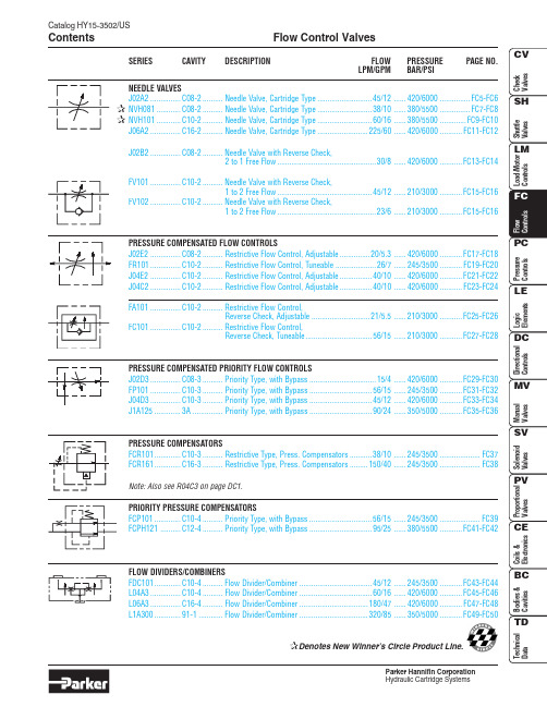
Catalog HY15-3502/USFlow Control Valves ContentsParker Hannifin CorporationFC1Flow Control ValvesCatalog HY15-3502/USTechnical TipsParker Hannifin CorporationINTRODUCTIONThis technical tips section is designed to help familiarize you with the Parker line of Flow Control Valves. In this section we present common options available as well as a brief synopsis of the operation and applications of the various product offered in this section. The intent of this section is to help you in selecting the best products for your application.Adjustment Types: Parker offers four primary types of adjustments for most of the flow control products.Samples of these types are shown below. Please note all options may not be available for all valves. Consult the individual catalog pages for more details.Screw Adjustment - Valve can be adjusted with an allen wrench. Lock nut included to maintain desired setting after adjustment. This is the most common adjustment option available on most Parker products.Knob Adjustment - An aluminum knob is added to the standard screw adjustment. A lock knob is provided to help maintain the desired setting after adjustment. Parker offers knob conversion kits for most flow control valves. For kit numbers consult the individual valve pages.Fixed Style - In most cases, the Fixed Style product is a screwadjustable product with a steel collet threaded over the adjustment.These valves are preset at the factory. Should the valve need to adjusted, the star washer andaluminum plate can be removed from the top of the assembly exposing the adjustment.Tamper Resistant - The tamper resistant option is a screw adjustable valve with a steel cap installed to con-ceal the adjustment. The cap is designed so the internal edges clamp into the groove of the valve adapter. Once the cap is installed, it cannot be removed without damaging the cap and the valve.When a valve is ordered with the tamper resistant option, it will be preset at the factory, and the cap will be included in a separate plastic bag to allow for fine tuning at the customer site. Parker offers tamper re-sistant cap conversion kits for most flow control valves.For kit numbers consult the individual valve pages.Seals: The Winner’s Circle products feature astandard 4301 Polyurethane “D”-Ring. The “D”-Ring eliminates the need for backup rings.The majority of the products are available in Nitrile or Fluorocarbon Seals. You should match the seal compatibility to the temperature and fluid being used in your application.Fine Meter Options: Fine meter needles are offered on some needle valve series. When this option isspecified, the standard needle is replaced by a slotted needle. The slotted needle restricts substantially more flow giving you finer control in the small flow ranges.Obviously, the maximum flow capacity of the needle valve is decreased with the fine meter option.Coarse NeedleFine NeedleCOMMON OPTIONSAs you will see, Parker offers a variety of Flow Control products. As such, some of the options mentioned below may not be available on all valve models. Consult the model coding and dimensions of each valve for specifics.Here are some of the common options available.Catalog HY15-3502/USFlow Control Valves Technical TipsParker Hannifin CorporationFC2FC3Flow Control ValvesCatalog HY15-3502/USTechnical TipsParker Hannifin CorporationCatalog HY15-3502/USFlow Control Valves Technical TipsParker Hannifin CorporationFC4Needle Valve Series J02A2Catalog HY15-3502/USFC5Parker Hannifin Corporation Technical InformationCatalog HY15-3502/USNeedle Valve Series J02A2FC6Parker Hannifin Corporation Technical InformationNeedle Valve Series NVH081Catalog HY15-3502/USFC7Parker Hannifin Corporation Technical InformationHardened, precision ground parts for durability Compact size for reduced space requirements Fine adjustment needle option available for precise Polyurethane “D”-Ring eliminates backup rings and Valve meters flow in either direction, but (2 to 1) is the preferred direction for lowest leakage at shut offCatalog HY15-3502/USNeedle Valve Series NVH081FC8Parker Hannifin Corporation Technical InformationNeedle Valve Series NVH101Catalog HY15-3502/USFC9Parker Hannifin Corporation Technical InformationPerformance CurvesFlow vs. Inlet Pressure Hardened, precision ground parts for durability Compact size for reduced space requirements Fine adjustment needle option available for precise Polyurethane “D”-Ring eliminates backup rings and Valve meters flow in either direction, but (2 to 1) is the preferred direction for lowest leakage at shut offCatalog HY15-3502/USNeedle Valve Series NVH101FC10Parker Hannifin Corporation Hydraulic Cartridge SystemsTechnical InformationNeedle Valve Series J06A2Catalog HY15-3502/USFC11Parker Hannifin Corporation Hydraulic Cartridge SystemsTechnical InformationCatalog HY15-3502/USNeedle Valve Series J06A2FC12Parker Hannifin Corporation Hydraulic Cartridge SystemsTechnical InformationNeedle Valve Series J02B2Catalog HY15-3502/USFC13Parker Hannifin Corporation Hydraulic Cartridge SystemsTechnical InformationCatalog HY15-3502/USNeedle Valve Series J02B2FC14Parker Hannifin Corporation Hydraulic Cartridge SystemsTechnical InformationNeedle ValveSeries FV101 and FV102Catalog HY15-3502/USFC15Parker Hannifin Corporation Hydraulic Cartridge SystemsTechnical InformationFree FlowMetered FlowCatalog HY15-3502/USNeedle ValveSeries FV101 and FV102FC16Parker Hannifin Corporation Hydraulic Cartridge SystemsTechnical InformationP.C. Flow Control Valve Series J02E2Catalog HY15-3502/USFC17Parker Hannifin Corporation Hydraulic Cartridge SystemsTechnical InformationCatalog HY15-3502/USP.C. Flow Control Valve Series J02E2FC18Parker Hannifin Corporation Hydraulic Cartridge SystemsTechnical InformationFC19P.C. Flow Regulator Valve Series FR101Catalog HY15-3502/USParker Hannifin CorporationHydraulic Cartridge SystemsTechnical InformationAdjustable StyleSeries FR101Technical InformationAdjustable StyleSeries J04E2Technical InformationAdjustable StyleSeries J04C2Technical InformationSeries FA101Technical InformationSeries FC101Technical Information(2)Catalog HY15-3502/USP.C. Priority Flow Control Valve Series J02D3FC30Parker Hannifin Corporation Technical InformationFC31P.C. Priority Flow Regulator Valve Series FP101Catalog HY15-3502/USParker Hannifin Corporation Technical InformationFeaturesHardened, precision ground parts for durability Cartridge design(2)FC32Catalog HY15-3502/USP.C. Priority Flow Regulator ValveSeries FP101Parker Hannifin Corporation Technical InformationP.C. Priority Flow Control Valve Series J04D3Catalog HY15-3502/USFC33Parker Hannifin Corporation Technical Information(2)Catalog HY15-3502/USP.C. Priority Flow Control Valve Series J04D3FC34Parker Hannifin Corporation Technical InformationP.C. Priority Flow Control Valve Series J1A125Catalog HY15-3502/USFC35Parker Hannifin Corporation Technical Information(2)Catalog HY15-3502/USP.C. Priority Flow Control Valve Series J1A125FC36Parker Hannifin Corporation Technical InformationFC37Catalog HY15-3502/USParker Hannifin Corporation Restrictive Type Pressure Compensator Valve Series FCR101Technical Information(1)(3)FC38Catalog HY15-3502/USRestrictive Type Pressure Compensator ValveSeries FCR161Parker Hannifin Corporation Technical Information (3)FC39Catalog HY15-3502/USParker Hannifin Corporation Priority Type Pressure Compensator Valve Series FCP101Technical InformationFC40Parker Hannifin CorporationPriority Type Pressure Compensator Valve Series FCPH121Catalog HY15-3502/USFC41Parker Hannifin Corporation Technical InformationCatalog HY15-3502/USPriority Type Pressure Compensator Valve Series FCPH121FC42Parker Hannifin Corporation Technical InformationFlow Divider/Combiner Valve Series FDC101Catalog HY15-3502/USFC43Parker Hannifin Corporation Technical InformationDivider Outlets Combiner Inlets(3)Divider Inlet Combiner OutletCatalog HY15-3502/USFlow Divider/Combiner Valve Series FDC101FC44Parker Hannifin Corporation Technical InformationFlow Divider/Combiner Valve Series L04A3Catalog HY15-3502/USFC45Parker Hannifin Corporation Technical InformationDivider Outlets Combiner Inlets (3)Divider InletCatalog HY15-3502/USFlow Divider/Combiner Valve Series L04A3FC46Parker Hannifin Corporation Technical InformationFlow Divider/Combiner Valve Series L06A3Catalog HY15-3502/USFC47Parker Hannifin Corporation Technical InformationDivider Outlets Combiner Inlets (3)Divider InletCatalog HY15-3502/USFlow Divider/Combiner Valve Series L06A3FC48Parker Hannifin Corporation Technical InformationFlow Divider/Combiner Valve Series L1A300Catalog HY15-3502/USFC49Parker Hannifin Corporation Technical InformationDivider Outlets Combiner Inlets。
Parker B Series 方向控制阀门说明书
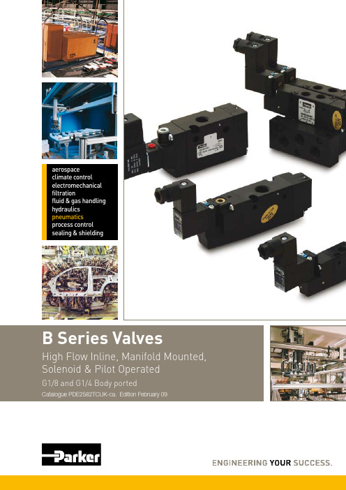
aerospaceclimate control electromechanical filtrationfluid & gas handling hydraulics pneumatics process controlsealing & shieldingDirectional Control Valves B SeriesCompact installation dimensions -flexible installationCompact dimensions, direct body porting and integral mounting holes are all features of the B series valve range. Valves may be mounted singly or on compact modular manifolds that can be extended to accomodate changes in the machine control system.High reliabilityValves easily comply with the requirements for component reliability in accordance with EU Machinery Directive standards EN 9 - and EN983.A wide range of solenoid valvesSolenoid operated versions of the B3 & B4 valves are fitted with interface to accept the 15mm wide solenoid and Form C / ISO 15 17 connector. The valve has small installation dimensions, low energy consumption. The B5 is also available with the mm wide solenoid suitable for (EN175301-803 form B) connector.The solenoid operators are available with or without manual overrides.Manifold mountingIEM stackable manifold system is designed to give maximum flexibility to system designers. Individual manifold bases stack together to form lightweight custom length manifold that can easily be modified to accommodate changes to system requirements. Different solenoid connector optionsA large range of solenoid connectors are available with or without suppression, LED and rectifier and complete with moulded lead.MaintenanceAll B series valves have reliable function and long service life. Spare solenoid and repair kits are available.PRODUCTS AND/ORsubsidiaries andthe informationand testing,herein, includingWARNINGSALE CONDITIONSThe items described in this document are available for sale by Parker Hannifin Corporation, its subsidiaries or its authorized distributors. Any sale contract entered into by Parker will be governed by the provisions stated in Parker’s standard terms and conditions of sale (copy available upon request).3The B series valves are fitted with dynamic bi-directional spool seals suitable for vacuum or pressures up to 10 bar.Under pressure radial expansion of the seal occurs to maintain sealing contact with the valve bore.“Wear Compensating System”This sealing method reduces friction gives lower pilot pressures, fast response and less wear. Valves do not require lubrication in operation but they can also be installed in systems that are lubricated.4Flow CharacteristicsB SeriesFlow characteristicsFlow capacities in accordance with ISO6358All pressures = effective pressureThe curves in the diagram below are typical onlyTechnical Data B3Port sizeG1/8Operating pressure. Vacuum - 10 bar Working temperature.Pneumatically operated valves. -10O C to + 50O C Solenoid operated valves. -10O C to + 50O C Response times:Single sol spring return Single sol air spring return 4/ 6ms Double solenoid operated 13/15ms Flow (acc. to ISO 6358) c = .3 b = 0.45 Qn = 13 l/s Qmax = 16 l/sCv = 0.75Technical Data B4Port sizeG1/4Operating pressure. Vacuum - 10 bar Working temperature.Pneumatically operated valves. -10O C to + 50O C Solenoid operated valves. -10O C to + 50O C Response times:Single sol spring return Single sol air spring return 38/38ms Double solenoid operated 3/ 4ms Flow (acc. to ISO 6358) c = 4.56 b = 0.30Qn = 19.5 l/s Qmax = 3 l/sCv = 1.Technical Data B5Port sizeG1/4Operating pressure. Vacuum - 10 bar Working temperature.Pneumatically operated valves. -10O C to + 50O C Solenoid operated valves. -10O C to + 50O C Response times:Single sol spring return Single sol air spring return 38/40ms Double solenoid operated 16/18ms Flow (acc. to ISO 6358) Qn = 4 l/s Qmax = 37 l/sCv = 1.45Directional Control ValvesB SeriesB4 valveValve body Anodised aluminiumSpool Acetal plastic/ Anodised aluminium Piston Acetal plastic /Anodised aluminium LiningReinforced thermoplastic End covers Anodised aluminium Sliding seals Thermoplastic U-rings, O-rings Nitrile rubber End cover sealingsNitrile rubber Push buttom for manual changeoverAcetal plastic End cover screws Stainless steel SpringsStainless steel Mounting screws for solenoidZinc-plated steelB4 AccessoriesIEM manifold Glass filled nylon End platesAnodised aluminium Manifold connecting screwsZinc plated steelB3 valveValve body Anodised aluminium End covers Anodised aluminium orReinforced thermoplastic Spool Aluminium + nitrile rubberPistonAcetal plastic/ Anodised aluminium U-rings, O-rings Nitrile rubber End cover sealings Nitrile rubber End cover screws Stainless steelSprings Dacromet ® - processed steel,Stainless steel Mounting screws for solenoidStainless steelB3 AccessoriesIEM manifold Glass filled nylon End platesAnodised aluminium Manifold connecting screwsZinc plated steelB5 valveValve body Anodised aluminiumSpool Aluminium + nitrile rubber Piston Brass LiningBrassEnd covers Anodised aluminium Sliding seals Thermoplastic U-rings, O-rings Nitrile rubber End cover sealings Nitrile rubber End cover screws Stainless steel SpringsStainless steel Mounting screws for solenoidZinc plated steelB5 AccessoriesIEM manifold Glass filled nylon End platesAnodised aluminium Manifold connecting screwsZinc plated steel6Metal Spool ValvesB3• G1/8 ports, 3/ , 5/ and 5/3 functions • Inlet-exhaust manifold facility • DIN rail mounting • Integral mounting holes • 1. watt solenoid actuators • FormC/ISO15 17 connector7Metal Spool ValvesB3Main data for Directional control valves, B3 SeriesSymbol Actuator Return Signal pressure Changeover Weight Voltage Order codeQtymin, bar time, ms Kg at 6 bar at 6 baractua./return actua./returnAirAir3,0/3,0 1 /1 0,10 B395000XXH 1Vented centre Self centring positionAir Air 3,0/3,01 /10,10B305000XXH1Pressurised Self centringcentre positionElectric Air 1,4/1/4 9/3 0,13 4 VDC B3S5BB549H 1 0,09 Less solenoid B3S5BXXXXH 1 Electric Air 1,4/1/4 9/3 0,14 4 VDC B3A5BB549H 1 0,10 Less solenoid B3A5BXXXXH 1Metal Spool Valves B3 Main data for Directional control valves, B3 SeriesSymbol Actuator Return Signal pressure Changeover Weight Voltage Order code Qtymin, bar time, ms Kgat 6 bar at 6 baractua./return actua./returnElectric Electric 3,0/3,0 1 /1 0,18 4 VDC B365BB549H 1Vented centre Self centring0,09 Less solenoid B365BXXXXH 1 positionElectric Electric 3,0/3,0 1 /1 0,10 4 VDC B375BB549H 1Pressurised Self centring 0,09 Less solenoid B375BXXXXH 1centre positionInternal air supply to differential pilots and solenoids via port 1Silencers and push-in fittings are shown on page 7.Valves supplied with solenoid operators include standard P8C-D connector89Metal Spool ValvesB3Inlet Exhaust Manifolds for B3 series valvesStandard Base without Flow Controls Each kit contains:1 pcs Manifold Basepcs Mounting screws and nuts 3 pcs Tie Rods1 pcs Body-to-base Gasket and 1 pcs Base-to-Base GasketEnd platesStandard End Plates may be used with either of aboveManifold BasesEach kit contains:1 right and 1 left End Plate 3 pcs O-Rings3 pcs Blanking Plugs3 pcs Socket Head Cap Screws 3 pcs Flat Washers 3 pcs LockwashersIsolator Plug KitUsed to isolate the 1, 3 or 5 gallerybetween two Manifold Bases Each kit contains:3 pcs Isolator Plugs complete with O-rings.Manifold Blanking Plate Each kit contains:1 pcs Cover Platepcs Mounting Screws 1 pcs GasketUsed to blank off unused stations.Order code QtyOrder code QtyOrder code QtyMetal Spool Valves B3 Dimensions, B3 Valve SeriesAll dimensions in mm unless otherwise stated3/2 Body portedSingle solenoid operated air spring return / spring return Double solenoid operatedAir differential return Spring returnA130,5 136,7Air differential return Spring returnB67,0 73,103/2 Inlet Exhaust Manifold For B3 Body Ported ValvesManifolds - IEM Inlet Exhaust Manifold System5/2 Inlet Exhaust Manifold For B3 Body Ported ValvesAll dimensions in mm unless otherwise stated5/3 Body portedDimensions, B3 Valve Series• G1/4 ports, 3/ , 5/ and 5/3 functions • Inlet-exhaust manifold facility • DIN rail mounting • Integral mounting holes • 1. watt solenoid actuators • Form C / ISO 15 17 connectorMain data for Directional control valves, B4 SeriesSymbol Actuator Return Signal pressure Changeover Weight Voltage Order code Qtymin, bar time, ms Kgat 6 bar at 6 baractua./return actua./returnAir Air 3,0/3,0 16/19 0, 04 B496000XXF 1Vented centre Self centringpositionAir Air 3,0/3,0 16/19 0, 04 B406000XXF 1Pressurised Self centringcentre positionElectric Air 1,5/1,5 15/17 0, 0 4 VDC B4S6AB549F 10,170 Less solenoid B4S6AXXXXF 1Electric Air 1,5/1/5 15/17 0, 41 4 VDC B4A6AB549F 10,19 Less solenoid B4A6AXXXXF 1Symbol Actuator Return Signal pressure Changeover Weight Voltage Order code Qtymin, bar time, ms Kgat 6 bar at 6 baractua./return actua./returnElectric Electric 3,0/3,0 16/18 0, 89 4 VDC B466AB549F 1Vented centre Self centring 0,191 Less solenoid B466AXXXXF 1positionElectric Electric 3,0/3,0 16/18 0, 89 4 VDC B476AB549F 1Pressurised Self centring 0,191 Less solenoid B476AXXXXF 1centre positionInternal air supply to differential pilots and solenoids via port 1Silencers and push-in fittings are shown on page 7.Valves supplied with solenoid operators include standard P8C-D connectorInlet Exhaust Manifolds for B4 series valvesStandard Base without Flow Controls Each kit contains:1 pcs Manifold Basepcs Mounting screws and nuts pcs Tie Rods1 pcs Body-to-base Gasket and 1 pcs Base-to-Base GasketEnd platesStandard End Plates may be used with either of aboveManifold BasesEach kit contains:1 right and 1 left End Plate 3 pcs O-Rings3 pcs Blanking Plugspcs Socket Head Cap Screws pcs Flat Washers pcs LockwashersIsolator Plug KitUsed to isolate the 1, 3 or 5 gallery between two Manifold Bases Each kit contains:3 pcs Isolator Plugs complete with O-ringsManifold Blanking plate Each kit contains:1 pcs Cover Platepcs Mounting Screws 1 pcs GasketUsed to blank off unused stations.Order code QtyOrder code Qty Port Size Order code QtyOrder code QtyDimensions, B4 Valve Series3/2 Body portedSingle solenoid operated air spring return / spring returnAll dimensions in mm unless otherwise stated5/2 Body portedSingle solenoid operated air spring return / spring returnSingle solenoid operated air pilot return Single solenoid operated air pilot returnDouble solenoid operated Double solenoid operatedAir differential returnSpring returnA154,0156,0Air differential returnSpring returnB166,0168,0ADimensions, B4 Valve Series3/2 Body portedDouble air pilot operatedAll dimensions in mm unless otherwise stated5/2 Body portedDouble air pilot operatedAir pilot operated air spring return / spring returnAir pilot operated air spring return / spring returnAir differential returnSpring returnC107,5109,5Air differential returnSpring returnD1 0,01 ,0CD5/3 Body portedDouble air pilot return 5/3 Body portedDouble solenoid operated3/2 Inlet Exhaust Manifold For B4 Body Ported ValvesP e r s t a t i o nManifolds - IEM Inlet Exhaust Manifold System5/2 Inlet Exhaust Manifold For B4 Body Ported Valves3348,54,541,510,65837118186,89,58G3/86,6P e r s t a t i o n3348,54,541,510,6599,587,518186,8599,5G3/86,6• G1/4 ports, 3/ , 5/ and 5/3 functions • Inlet-exhaust manifold facility • Integral mounting holes • 5 watt solenoid actuators• EN175301-803 Industrial Form B connectorMain data for Directional control valves, B5 Series (G1/4 threaded ports)Symbol Actuator Return Signal pressure Changeover Weight Voltage Order code Qtymin, bar time, ms Kgat 6 bar at 6 baractua./return actua./returnElectric Electric 3,0/3,0 16/18 0, 89 4 VDC B566BCB49C 1Vented centre Self centring 0,191 Less solenoid B566BCNXXC 1positionElectric Electric 3,0/3,0 16/18 0, 89 4 VDC B576BCB49C 1Pressurised Self centring 0,191 Less solenoid B576BCNXXC 1centre positionOrder solenoid connectors separately, see page 25 for part numbers.Internal air supply to differential pilots and solenoids via port 1Silencers and push-in fittings are shown on page 7.Inlet Exhaust Manifolds for B5 series valvesStandard Base without Flow Controls Each kit contains:1 pcs Manifold Basepcs Mounting screws and nutspcs Tie Rods1 pcs Body-to-base Gasket and1 pcs Base-to-Base GasketEnd platesStandard End Plates may be used with either of above Manifold BasesEach kit contains:1 right and 1 left End Plate3 pcs O-Rings3 pcs Blanking Plugspcs Socket Head Cap Screwspcs Flat Washerspcs LockwashersIsolator Plug KitUsed to isolate the 1, 3 or 5 gallery between two Manifold BasesEach kit contains:3 pcs Isolator Plugs completewith O-ringsManifold Blanking plateEach kit contains:1 pcs Cover Platepcs Mounting Screws1 pcs GasketUsed to blank off unused stations.Order code Qty ManifoldBlanking plateOrder code Qty Isolator Plug kitPort Size Order code QtyOrder code Qty1Metal Spool ValvesB5Dimensions, B5 Valve SeriesAll dimensions in mm unless otherwise stated3/2 Body portedSingle solenoid operated air spring return / spring return5/2 and 5/3 Body portedSingle solenoid operated air spring return / spring returnDouble solenoid operatedDouble solenoid operated2 Position3 PositionA51,16 ,7Metal Spool ValvesB5Manifolds - IEM Inlet Exhaust Manifold System5/2 Inlet Exhaust Manifold For B5 Body Ported ValvesAll dimensions in mm unless otherwise stated6,699,587,59,559G3/845,410,65181830,7P e r S t a t i o n4,53348,53Solenoid Valve OptionsB SeriesValve supplied without solenoidsB3 and B4 valves are designed to accept 15mm solenoid operator / connector CECC/EN 175301-803 Form C/ISO 15 17. Solenoidoperated valves may be ordered without the solenoid operator and connector by substituting XXXX in positions 6 to 9 of the part number. Example B3T5BXXXXH is part number for 5/ Single solenoid operated spring return valve without solenoid operator and standard connector. See Fig 1.B5 valves are designed to accept mm solenoid operator/connector EN175301-803 Industrial Form B. Solenoid valves may be ordered without the coil and connector and are supplied with the solenoid operator fitted to the valve. See Fig .Example B5E6BCNXXC is part number for 5/ Single solenoid operated valve fitted with the solenoid operator having flush locking M/O without coils and connectors.Fig .Fig 1.4Solenoid OperatorsB Series15mm Solenoid Operators for B3 and B4 ValvesElectrical connection EN 175302-803 C/ISO15217 (Ex DIN 43650C)Self tapping screwTorque: .7 - .9 Nm (6 - 8 In. Lbs.)Solenoids 15mm NC, standard(Note! Mounting screws included with basic valve) Voltage WeightOrder code WeightOrder code WeightOrder codeKg Without manual Kg Override, blue, Kg Override, yellow,override non locking flush locking flushSolenoid coils to suit ‘N’ enclosure type22mm 3-Pin EN 175301-803 Industrial Form BCoil Voltage Order code Weight (kg)Solenoid coils for B5 valvesSolenoid Operator Kit for B5 valvesEach kit contains:1 large ‘O’ ring for operator base 1 small ‘O’ ring for operator base mounting screwsSpare solenoid nutsValves with vented exhaust are fitted with diffuser plastic nutSolenoid Valves B SeriesSolenoid Connectors / Cable Plugs EN175301-803Description Order code Order code15mm Form C/ISO15 17 mm Industrial Form BSuitable for B3 & B4 valves Suitable for B5 valves56Solenoid ValvesB SeriesMale straight connectors - Parallel threadTube dia 1 Thread Ordercode Box Qty BFittingsSilencersPort Ordercode Pack QtyCable Plug Dimensions (mm)Solenoid valves P2E-•V ...122Accessories, Service and Replacement PartsCable plugs form C / ISO 15217 for B3 & B4 valves Cable plugs Form B for B5 valvesCable plugs form C / ISO 15217with cables for B3 & B4 valves7Accessories, Services and Replacement PartsB SeriesB3,B4 and B5 Spool/Body repair kits contain:SpoolSpool sealsLip seal – operator pistons GasketsSpool springs Grease packetB3 series valvesManifold gasket kits3/ IEM Gasket kit (10 valve/manifold gaskets)5/ IEM Gasket kit (10 valve/manifold gaskets)B4 series valves5/3 solenoid and remote pilot operated valves – CE Spool/Body repair kit 5/3 solenoid and remote pilot operated valves – PC Spool/Body repair kitManifold gasket Kits.3/ IEM Gasket Kit (10 valve/manifold gaskets)5/ IEM Gasket Kit (10 valve/manifold gaskets)B5 series valves5/3 solenoid and remote pilot operated valves – CE Spool/Body repair kit 5/3 solenoid and remote pilot operated valves – PC Spool/Body repair kitManifold gasket Kits.3/ & 5/ IEM Gasket kit PS 884P (10 valve/manifold gaskets)Solenoid coils for B5 valvesSolenoid coils to suit ‘N’ enclosure type mm 3-Pin Industrial Form BPS2980F PS2981FPS4503F PS4504FSolenoid operator kitEach kit contains:1 Large ‘O’ring for operator base 1 Small ‘O’ ring for operator base PS2884PPS4580F PS4581FPS 2803P PS2804PAE – UAE, Dubai Tel: +971 4 8875600 ********************AR – Argentina, Buenos Aires Tel: +54 3327 44 4129AT – Austria, Wiener Neustadt Tel: +43 (0)2622 23501-0 *************************AT – Eastern Europe, Wiener NeustadtTel: +43 (0)2622 23501 970 ****************************AU – Australia, Castle Hill Tel: +61 (0)2-9634 7777AZ – Azerbaijan, Baku Tel: +994 50 2233 458****************************BE/LX – Belgium, Nivelles Tel: +32 (0)67 280 900*************************BR – Brazil, Cachoeirinha RS Tel: +55 51 3470 9144BY – Belarus, Minsk Tel: +375 17 209 9399*************************CA – Canada, Milton, Ontario Tel: +1 905 693 3000CH – Switzerland, Etoy Tel: +41 (0) 21 821 02 30*****************************CN – China, Shanghai Tel: +86 21 5031 2525CZ – Czech Republic, Klecany Tel: +420 284 083 111*******************************DE – Germany, Kaarst Tel: +49 (0)2131 4016 0*************************DK – Denmark, Ballerup Tel: +45 43 56 04 00*************************ES – Spain, Madrid Tel: +34 902 33 00 01 ***********************FI – Finland, Vantaa Tel: +358 (0)20 753 2500 *************************FR – France, Contamine s/Arve Tel: +33 (0)4 50 25 80 25 ************************GR – Greece, Athens Tel: +30 210 933 6450 ************************HK – Hong Kong Tel: +852 2428 8008HU – Hungary, Budapest Tel: +36 1 220 4155*************************IE – Ireland, Dublin Tel: +353 (0)1 466 6370 *************************IN – India, MumbaiTel: +91 22 6513 7081-85IT – Italy, Corsico (MI) Tel: +39 02 45 19 21 ***********************JP – Japan, Fujisawa Tel: +(81) 4 6635 3050KR – South Korea, Seoul Tel: +82 2 559 0400KZ – Kazakhstan, Almaty Tel: +7 7272 505 800****************************LV – Latvia, Riga Tel: +371 6 745 2601 ************************MX – Mexico, Apodaca Tel: +52 81 8156 6000MY – Malaysia, Subang Jaya Tel: +60 3 5638 1476NL – The Netherlands, OldenzaalTel: +31 (0)541 585 000 ********************NO – Norway, Ski Tel: +47 64 91 10 00************************NZ – New Zealand, Mt Wellington Tel: +64 9 574 1744PL – Poland, Warsaw Tel: +48 (0)22 573 24 00 ************************PT – Portugal, Leca da Palmeira Tel: +351 22 999 7360**************************RO – Romania, Bucharest Tel: +40 21 252 1382*************************RU – Russia, Moscow Tel: +7 495 645-2156************************SE – Sweden, Spånga Tel: +46 (0)8 59 79 50 00 ************************SG – Singapore Tel: +65 6887 6300SK – Slovakia, Banská Bystrica Tel: +421 484 162 252**************************SL – Slovenia, Novo Mesto Tel: +386 7 337 6650**************************TH – Thailand, Bangkok Tel: +662 717 8140TR – Turkey, Istanbul Tel: +90 216 4997081 ************************TW – Taiwan, Taipei Tel: +886 2 2298 8987UA – Ukraine, Kiev Tel +380 44 494 2731*************************UK – United Kingdom, WarwickTel: +44 (0)1926 317 878 ********************US – USA, Cleveland Tel: +1 216 896 3000VE – Venezuela, Caracas Tel: +58 212 238 5422ZA – South Africa, Kempton ParkTel: +27 (0)11 961 0700*****************************Catalogue PDE2582TCUK-ca. Edition February 09Your local authorized Parker distributor© 2008 Parker Hannifin Corporation. All rights reserved.Parker WorldwideEuropean Product Information Centre Free phone: 00 800 27 27 5374(from AT, BE, CH, CZ, DE, EE, ES, FI, FR, IE, IT, PT, SE, SK, UK)Parker Hannifin LtdPneumatic Division Europe The Collins Centre,Lichfield South, Wall Island,Birmingham Road, Lichfield.WS14 0QP United Kingdom Tel.: +44 (0) 1543 483800Fax: +44 (0) 1543 483801/euro_pneumatic。
派克换向阀样本范文
派克换向阀样本范文派克换向阀(Parker Directional Control Valve)是一种用于控制液压系统中流体流向的设备。
它通常由阀体、阀芯、阀孔和控制杆等组成。
派克换向阀一般用于工业设备、机械工程、农业机械、建筑机械等领域。
派克换向阀具有多种不同的工作方式,包括手动控制和自动控制两种。
手动控制方式可以通过人工操作来改变阀芯的位置,从而改变流体的流向。
自动控制方式可以通过外部信号来改变阀芯的位置,实现对流体流向的自动控制。
派克换向阀还具有多种不同的功能,包括单向阀、溢流阀、节流阀等。
单向阀主要用于防止流体逆流,溢流阀主要用于调节流体的压力,节流阀主要用于调节流体的流量。
这些功能可以根据不同的工作需求进行选择和组合,从而实现对液压系统的精确控制。
除了基本的功能外,派克换向阀还可以根据用户的需求进行个性化定制。
例如,可以根据不同的工作场合选择不同的阀孔和阀芯结构,以满足不同的流量和压力要求。
此外,还可以根据用户的需要进行材料和密封件的选择,以适应不同的介质和工作温度。
派克换向阀还具有良好的节能和环保性能。
它采用先进的流体动力学设计和优化的液压系统结构,能够减少能源的消耗和环境污染。
同时,它还具有低噪音、高效率和长寿命等优点,在实际应用中可以大大提高设备的工作效率和可靠性。
总的来说,派克换向阀是一种功能强大、性能稳定、可靠耐用的液压控制设备。
它能够满足不同工作场合的需求,提高设备的效率和可靠性,减少能源的消耗和环境污染。
因此,派克换向阀在工业生产和机械工程中具有重要的应用价值。
派克汉尼汾 parker 叶片泵 4DP03-06E

Y-外泄口
1) 供货时按订货要求的先导回路连接方式 安装螺堵。
♦ 先导控制压力(X 口) - 不带 R1 选项
- 带 R1 选项
♦ 最高工作压力 - 内泄式 - 外泄式
最低:T+35 bar 最高:105 bar 最低:T+45 bar 最高:350 bar
注:R1 选项先导减压阀出厂设定压力为:50 bar
P, A, B
T
Y
350 bar
15 bar
15 bar
1 = 丁晴橡胶 NBR, 标准型 5 = 氟橡胶 FPM(Viton®)
9 电磁铁电源
G12 = 12 V DC
10 电气连接
无代号 = 不带电插头 C1 = PG11 插头
11 先导回路连接
无代号 = 外控外泄 X = 内控外泄
Y = 外控内泄 XY = 内控内泄
12 液压辅件
无代号 = 不带先导回路减压阀(先导控制压力 X < 105 bar) R1= 带先导回路减压阀(先导控制压力 X > 105 bar)
4DP06-E
-阶跃信号 0 ~ 100%
50 ms
60 ms
-阶跃信号 100% ~ 0
50 ms
70 ms
-阶跃信号 +100% ~ -100% 60 ms
80 ms
♦ 工作油液
石油基抗磨液压油(符合 DENISON HF-0 及 HF-2 规
范),如:符合 DIN 51524/25 标准的矿物油。样本规
350 bar
350 bar
15 bar
♦ 流量
见“特性曲线”
♦ 公称流量(每控制边压差△P = 5 bar 时)
Parker Hannifin 方向控制阀门系列D31DW、D31NW、D 1VW 产品目录说明书
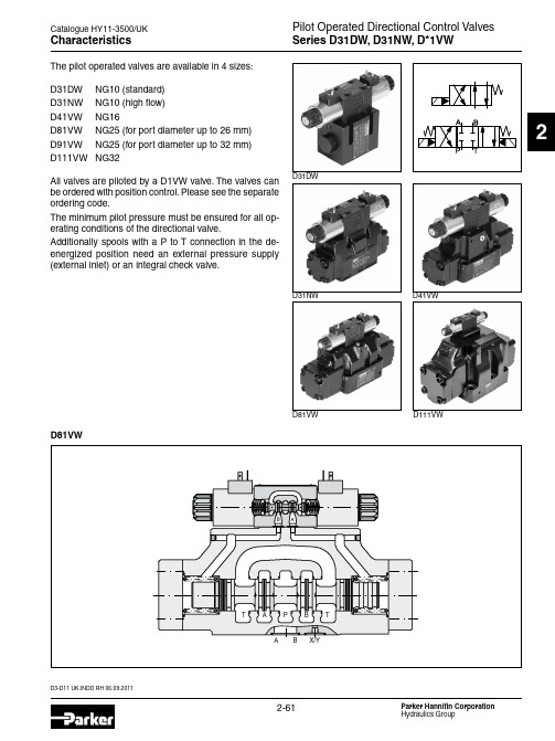
D3-D11 UK.INDD RH 06.09.2011Pilot Operated Directional Control Valves Series D31DW, D31NW, D*1VWCatalogue HY11-3500/UK2CharacteristicsThe pilot operated valves are available in 4 sizes:D31DW NG10 (standard)D31NW NG10 (high flow)D41VW NG16D81VW NG25 (for port diameter up to 26 mm)D91VW NG25 (for port diameter up to 32 mm)D111VWNG32All valves are piloted by a D1VW valve. The valves can be ordered with position control. Please see the separate ordering code.The minimum pilot pressure must be ensured for all op-erating conditions of the directional valve.Additionally spools with a P to T connection in the de-energized position need an external pressure supply (external inlet) or an integral check valve.D81VWD31DWD31NW D41VWD81VW D111VWPilot Operated Directional Control Valves Series D31DW, D31NW, D*1VWD3-D11 UK.INDD RH 06.09.2011Catalogue HY11-3500/UK2Ordering CodeSpoolSeriesSpool 1)2)Not for D31NW available 3)Not for D31NW and D111VW available 4)For D31NW and D111VW only pilot valve with detent availableD3-D11 UK.INDD RH 06.09.2011Pilot Operated Directional Control Valves Series D31DW, D31NW, D*1VWCatalogue HY11-3500/UK2Ordering CodeSolenoid options Solenoid voltageDesign series(not required for ordering)Pilot oil supply and drain optionsAcces-sories Further spool types and solenoid voltages on request.Explosion proof solenoids EEx me ll see catalogue HY11-3343. Download:/euro_hcd - see “Literature”Connector as per EN 175301-803,without plug(Please order plugseparately)Seals Code Seals N NBR VFPM Code Accessories omit Standard valve w/o accessories 3A Pilot choke, meter-out 3B Pilot choke, meter-in 3C Pilot with pressure reducing valve 3D 8)Stroke adjustment side B 3E 8)Stroke adjustment side A3F 8)Stroke adjustment side A and B 3R meter-out + pressure reducing valve 1Tmeter-in + pressure reducing valveCode Solenoid option omit Standard solenoid without options T without manual override 7)To be used in combination with rectifier plugs at 120VAC / 230VAC power sup-ply.Code Solenoid voltageK 12V =J 24V =U 7)98V =G 7)205V =Y 110V 50Hz / 120V 60Hz T230V 50Hz / 240V 60Hz5)N ot for D31DW, D91VW and D111VW available.6) N ot for spools 002, 007, 009, 014, 030, 031, 032, 054 available.Code Inlet Outlet 1Internal External 2External External 3 5)Integral check valve External 4 6)Internal Internal 5External Internal 6 5)Integral check valveInternal8)Only D31, D41, D81, D91 available.WCatalogue HY11-3500/UK2Ordering CodeWith inductive position controlPilot Operated Directional Control ValvesSeries D31DW, D*1VW Induct. Position ControlD3-D11 UK.INDD RH 06.09.2011D3-D11 UK.INDD RH 06.09.2011Catalogue HY11-3500/UK2Ordering Code6)The plug M12 x 1 for the position control is included. The monitor switch has to be located on the side to which the spool moves from the spring offset position. For 4/3-way valves two switches are used.Pilot oil supply and drain options4)To be used in combination with rectifier plugs at 120VAC / 230VAC power supply.Code Solenoid voltageK 12V =J 24V =U 4)98V =G 4)205V =2)N ot for D31DW, D91VW and D111VW available..3) N ot for spools 002, 007, 009, 014, 030 available.Code Inlet Outlet 1Internal External 2External External 3 2)Integral check valve External 4 3)Internal Internal 5 External Internal 6 2)Integral check valveInternalCode Solenoid option omit Standard solenoid without options T 5)without manual override5)For hydraulic presses according to the safety regulations EN 693, solenoid op-tion “T“ (without manual override) and accessories “I4N“, “I5N“ or “I6N“ (start position monitored) are required.Solenoid optionsSolenoid voltage Design series(not required for ordering)Acces-sories Connector as per EN 175301-803,without plug(Please order plugseparately.SealsCode Seals N NBR VFPM Code Spool positionPosition control I3NCEnd positionmonitored, side A and BI6N6)Start positionmonitored, side A and BI2N C, B, E, F (all spools)C, K, M (spool 9)End position monitored, side B I5N 6)Start position monitored, side B I1N C, H, K, M (all spools)C, E, F (spool 9)End position monitored, side A I4N 6)Start position monitored, side AAttentionThe adjustment of the position control is factory set and sealed.Replacement and repairs can only be undertaken by the manufacturer.WPilot Operated Directional Control ValvesSeries D31DW, D*1VW Induct. Position ControlPilot Operated Directional Control Valves Series D31DW, D31NW, D*1VWD3-D11 UK.INDD RH 06.09.2011Catalogue HY11-3500/UK2Technical DataWith electrical connections the protective conductor (PE W ) must be connected according to the relevant regulations.D3-D11 UK.INDD RH 06.09.2011Pilot Operated Directional Control Valves Series D31DW, D31NW, D*1VWCatalogue HY11-3500/UK2Electrical characteristics of position control M12x1Position ControlM12 pin assignment1 Us 18 (42V)2 Out B: normally open3 0V4 Out A. normally closed 5Earth groundDefinitionsStart position monitored:The valve is de-energized. The inductive switch gives a signal at the moment when the spool leaves the spring offset position (below 15% spool stroke).At the switching point the spool is located within the closed position. It is secured that only the flow paths of the offset position are granted.The switch can only be located on the opposite side of the solenoid for direct operated valves.Delivery includes plug M12 x 1 (see accessories, plug M12x1; order no.: 5004109).End position monitored:The inductive switch gives a signal before the end position is reached (above 85% spool stroke).Pilot Operated Directional Control Valves Series D31DW, D31NW, D*1VWD3-D11 UK.INDD RH 06.09.2011Catalogue HY11-3500/UK2Flow Curve DiagramsD31DW and D41VWThe flow curve diagram shows the flow versus pressure drop curves for all spool types. The relevant curve number for each spool type, operating position and flow direction is given in the table below.All characteristic curves measured with HLP46 at 50°C.D31NWD31DWD31NWD3-D11 UK.INDD RH 06.09.2011Pilot Operated Directional Control ValvesSeries D31DW, D31NW, D*1VWCatalogue HY11-3500/UK2Flow curve D31NWD81/D91VW and D111VWFlow curve D81VWFlow curve D41VW Flow Curves / Integral Check ValveIntegral check valve in the P portMounting an integral check valve in the P port is necessary to build up pilot pressure for valves with P to T connection and internal pilot oil supply. The pressure difference at the integral check valve (see performance curves) is to be added to all flow curves of the P-port of the main valve. Directional valves with an integral check valve are availablefor the series D31NW, D41VW and D81VW.All characteristic curves measured with HLP46 at 50°C.Pilot Operated Directional Control Valves Series D31DW, D31NW, D*1VWD3-D11 UK.INDD RH 06.09.2011Catalogue HY11-3500/UK2open,closedM6 DIN906M6 DIN906Slip-in orifice in pilot p-port(drawn offset)All orifice sizes for standard valvesPilot oil inlet (supply) and outlet (drain)Series D31DWSeries D41VWSeries Series Pilot Oil OptionsPilot Operated Directional Control Valves Series D31DW, D31NW, D*1VWCatalogue HY11-3500/UK2D31NWD31DWDimensionsThe space necessary to remove the plug per EN 175301-803, design type AF is at least 15 mm. The torque for the screw M3 of the plug has to be 0.5 to 0.6 Nm.* Please add for each sandwich plate +40mm (pressure reducing valve, choke valve meter-in/-out).* Please add for each sandwich plate +40mm (pressure reducing valve, choke valve meter-in/-out).Pilot Operated Directional Control Valves Series D31DW, D31NW, D*1VWCatalogue HY11-3500/UK2DimensionsThe space necessary to remove the plug per EN 175301-803, design type AF is at least 15 mm. The torque for the screw M3 of the plug has to be 0.5 to 0.6 Nm.D81VW, D91VWD41VW* Please add for each sandwich plate +40mm (pressure reducing valve, choke valve meter-in/-out).* Please add for each sandwich plate +40mm (pressure reducing valve, choke valve meter-in/-out).Pilot Operated Directional Control ValvesSeries D31DW, D31NW, D*1VW Catalogue HY11-3500/UK2 D111VWDimensionsThe space necessary to remove the plug as per EN 175301-803, design type AF is at least 15 mm.The torque for the screw M3 of the plug has to be 0.5 to 0.6 Nm.* Please add for each sandwich plate +40mm (pressure reducing valve, choke valve meter-in/-out).Catalogue HY11-3500/UKNotes。
派克阀样本手册软件版9

(2) In
(1) Out
Dimensions Millimeters (Inches)
DL081K
Ø 12.6 (.48)
(1)
27.8 (1.09)
(2)
39.3 (1.55)
Ø 25.4 (1.0)
3/4-16 UNF-2A Thread
Ø 2.4 (.09) Thru For Roll Pin Attachment 1/4-20 UNC-2A Thread
DMH085C2 ....... C08-4 .......... 3 Position, 4 Way, Open Center,
.............................................. Pull to Shift and Push to Shift ........................... 15/4 ...... 350/5000 ........ MV11-MV12 PV
PSI Bar 100 6.9
Hydraulic Oil 150 SSU @ 100°F (32 cSt)
Pressure Drop ( P)
75 5.1
50 3.5
25 1.7
0 LPM
0 GPM
7.6
15.1
22.7
30.3
2
4
6
8
Flow (Q)
Specifications
Out (1) In (2)
32.2 (1.27)
Detent Position
54.6 (2.15)
31.8 (1.25)
28.2 (1.11)
7/8" Hex. 20 Nm (15 lb. ft.) Torque
派克(parker) O形圈密封样本
!"
!O 14.00 mm 1.78 mm N674-70 !"# A70 O-Ring,14 x 1.78, 2-015, N674-70
7
2-xxx O
!
2-1xx
! d 1 (mm)
! d 2 = 2.62 mm
! d2 (mm) ! ! d 1 (mm) d2 (mm) ! ! d1 (mm) d 2 (mm)
2-xxx O O 100 C ! 12 O ! O
210 C)
!"#$%&'()
!"#
!
!"
C557-70
!" !"#$%#&'( !"#$%&'() ! !"#$%&'()*+ !"#$%"&'$( !"# !"#$ !"# !"#$%& !"#$%& !"#$%&' !"#$% !" !"#
P5008 A 93
. !" !"#$%& !"# O
!"
!"#$%&'( !"#$%&'() !"#O !"#$%& !"# ! O !"#$%&'( )*!"+,!"#$% !"# !"#$%&"' !"#$%&'()*+,-
!"#$%&'()* O !"#$%&'( !"#$%&'() 3
派克比例阀英文样本

PID00A-40*
Servo Drives for Positions-/Power Control
Compax 3F
News in Electrohydraulics
Details
Characteristics Ordering Code Technical Data Characteristic Curves Dimensions Characteristics Ordering Code Technical Data Characteristic Curves Dimensions Characteristics Ordering Code Technical Data Characteristic Curves Dimensions Characteristics Ordering Code Technical Data Characteristic Curves Dimensions Characteristics Technical Data, Ordering Code Construction Interface Program Characteristics Technical Data, Ordering Code Construction Interface Program Characteristics Technical Data, Ordering Code Construction Interface Program Characteristics Technical Data, Ordering Code Construction Interface Program Characteristics Technical Data, Ordering Code Construction Interface Program General Ordering Code Technical Data Technology Functions Interfaces / Multi-Axis Control Software Tools Dimensions / Accessories
- 1、下载文档前请自行甄别文档内容的完整性,平台不提供额外的编辑、内容补充、找答案等附加服务。
- 2、"仅部分预览"的文档,不可在线预览部分如存在完整性等问题,可反馈申请退款(可完整预览的文档不适用该条件!)。
- 3、如文档侵犯您的权益,请联系客服反馈,我们会尽快为您处理(人工客服工作时间:9:00-18:30)。
Female NPT thread (SAE 476) / Female NPT thread (SAE 476)
Visual index 3/2-way ball valves
KH 3/2 (S) p. O42
EO 24° cone end / EO 24° cone end / EO 24° cone end
KHBLOCK p. O51
Ball valve with Flange connection DIN EN 1092-1
2/2-way ball valve for block structure
O6
Catalogue 4100-8/UK
Visual index shut off valves and Line Rupture Valves “LRV”
DV p. O52
Valves
LD p. O53
EO 24° cone end / EO 24° cone end
VDHA p. O54
EO 24° cone end / EO 24° cone end
EO tube end / EO tube end
WV p. O55
ELA/ELAE p. O57
KH-A-S-71 p. O48
Ball valve with SAE Flange connection
KH-B4V-S p. O49
Ball valve with SAE Flange adapter connection
KHB5V-S p. O50
Ball valve with SAE Flange connection ISO 6162 (1/2)
RHZ5OMXS / p. O33
Male UN/UNF thread – O-ring (ISO 11926) / Triple-Lok® 37° flare end
RHV82EDMXS / p. O34
Triple-Lok® 37° flare end / Male UN/UNF thread – O-ring (ISO 11926)
RHV-M-ED / p. O16
EO 24° cone end / Male metric thread – ED-seal (ISO 9974)
RHDI / p. O18
Female BSPP thread (ISO 1179-1) / Female BSPP thread (ISO 1179-1)
KH-NPT (S) p. O40
Female NPT thread (SAE 476) / Female NPT thread (SAE 476)
EO 24° cone end / EO 24° cone end KH-BSPP (71) p. O39
Female BSPP thread (ISO 1179-1) / Female BSPP thread (ISO 1179-1)
KH 3/2-BSPP(S) p. O43
O
Female BSPP thread (ISO 1179-1) / Female BSPP thread (ISO 1179-1) / Female BSPP thread (ISO 1179-1)
O5
Catalogue 4100-8/UK
Valves
Visual index SAE ball valves/Ball valves for block structure
O
O3
Catalogue 4100-8/UK
Valves
Visual index Non return valves with Triple-Lok® connections
RHDMTXS / p. O29
Triple-Lok® 37° flare end / Triple-Lok® 37° flare end
RVP / p. O19
RHZ-R-ED / p. O15
Male BSPP thread – ED-seal (ISO 1179) / EO 24° cone end
RHZ-M-ED / p. O17
Male metric thread – ED-seal (ISO 9974) / EO 24° cone end
O4
Catalogue 4100-8/UK
Visual index 2/2-way ball valves
KH (S) p. O36
Valves
KH (71) p. O37
EO 24° cone end / EO 24° cone end KH-BSPP (S) p. O38
Female BSPP thread (ISO 1179-1) / Female BSPP thread (ISO 1179-1)
Steel
Materials: Body made of steel, coating DIN 50938-FE//A/T4, ball of hard chrome plated carbon steel, stem of zinc plated steel.
Seals: Ball seat of POM (e. g. Delrin), stem seal of NBR (e. g. Perbunan).
RHV42EDMXS / p. O30
RHZ42EDMXS / p. O31
Male BSPP thread – ED-seal (ISO 1179) / Triple-Lok® 37° flare end
RHV5OMXS / p. O32
Triple-Lok® 37° flare end / Male BSPP thread – ED-seal (ISO 1179)
RHV82EDMLOS / p. O27
Male metric thread – ED-seal (ISO 9974) / O-Lok® ORFS end
RHZ42EDMLOS / p. O24
O-Lok® ORFS end / Male BSPP thread – ED-seal (ISO 1179)
– for low pressure ratings
up to PN 10
DV
– for medium pressure ratings
up to PN 40
LD
Quarter turn Hand-operated ballure ratings
up to PN 500 bar
Ermeto Original Valves
Valves
Visual index Non return valves
RHD / p. O13
EO 24° cone end / EO 24° cone end RHV-R-ED / p. O14
EO 24° cone end / Male BSPP thread – ED-seal (ISO 1179)
KH-B1V-S p. O44
KH-B2V-S p. O45
Ball valve with SAE Flange connection
KH-B3V-S p. O46
Ball valve with SAE Flange connection
KH-A-S p. O47
Ball valve with SAE Flange connection
KH
– leakage rate hydraulic testing under test pressure: 0 drops per minute
The pressure specification PN for hand-operated shut-off valves and quarter turn ball valves applies to the design factor 1,5 (according DIN 3230 T5 and ISO 5208).
Range of hand-operated shut off valves and quarter turn ball valves
Non-return valves with nominal pressure ratings up to PN 420 bar:
– with tube connection both ends:
RHZ5OMLOS / p. O26
O-Lok® ORFS end / Male UN/UNF thread– O-ring (ISO 11926)
RHZ82EDMLOS / p. O28
O-Lok® ORFS end / Male metric thread – ED-seal (ISO 9974)
RHD
– with tube connection to male stud:
RHV/RHZ
– with female thread both ends:
RHDI
– valve cartridges:
RVP
– valve internal parts:
I-TL
– leakage rate hydraulic testing under test pressure: 1 drop per minute
EO 24° cone end / EO 24° cone end / EO 24° cone end
LRV 08 … 22L p. O58
Air-bleed valves
EO 24° cone end
O
O7
Catalogue 4100-8/UK
Valves
Range of non return valves and alternating valves