
eex,样本说明
防爆型EEx-d IIC-T5
功能: 芯 子 和 连 接 图 类 型 ( 见 表 2.2)
阀芯控制-见第 12 节 (不需要则省略): C = 主阀芯行程控制(不适于 E10P4K) D = 主阀芯移动速度控制 G = 主阀芯行程和移动速度控制,不适于 E10 阀 PF = 带∅ 0,8 阻尼器(P 路)过渡板,安装在电磁阀下
41 260/103 ED
2/16
2 – 阀芯功能 2.1 - MD1K阀芯功能
S型: 2个电磁铁 – 3位 弹簧对中
*TA型: 1个电磁铁,A侧 2 位 (中位 + 端位) 弹簧对中
*TC型: 1个电磁铁,B侧 2 位 (中位 + 端位) 弹簧对中
TA型: 1个电磁铁,A侧 2 端位 弹簧对中
TC型: 1个电磁铁,B侧 2 端位 弹簧对中
41 260/103 ED
防爆型电磁方向控制阀 EEx-dIIC
序列号 20
MD1K E4P4K E07P4K E5P4K E10P4K
CETOP 03 CETOP P05 CETOP 07 CETOP 08 CETOP 10
p max (见技术参数表)
Q max (见技术参数表)
— 该阀为电磁方向控制阀,其电磁铁完全符 合CENELEC EN 50.014、EN 50.018, CEI 31-1 及 CEI 31-8, 分 级 标 准 EEx-dIIC-T5。
E5P4K (选择C3)
内部先导 Y: M6x8堵塞 外部泄漏
E10P4K
X: M6x8堵塞 外部先导 Y: M6x8堵塞 外部泄漏
41 260/103 ED
内部先导 Y: M6x8堵塞 外部泄漏
X: 1/8” NPT堵塞 外部先导 Y: 1/8” NPT堵塞 外部泄漏
7/16
6 – 电气特性
6.1 电磁铁
线圈类型: D24 = 24 V 直流 AR110 = 110 V 交流(线圈 内带有直流式整流电路) AR230 = 230 V 交流
序列号:(序列号20-29外形及安装尺寸 不变)
密封: N = 矿物油用NBR密封 (标准) V = 特殊油用FPM密封
1.2 - E4P4K - E07P4K - E5P4K - E10P4K 先导式电磁阀型号及标注
TC 型: (见注 1) 1个电磁铁,A侧 2 端位 弹簧复位
41 260/103 ED
注 1 - E10P4K仅适于 S1 - S2 - S3 - S4 - S9 - TA – TC结构
3/16
3 - 液压油
通常应使用符合ISO 6h7tt4p:3///w3w标w.准bb1的58H.coLm或HLP液压油,对HFD-R(磷酸脂)应使用FPM 密封(选项V); 若使用其它油,如HFA、HFB、HFC时; 请咨询我们的技术部门。 当工作油温高于70°C时,将会导致液压油和密封过快老化与变质。应注意保持液压油稳定的物理和化学性能。
先导控制:内部先导省略 E = 外部先导(阀芯形式为S2-S4-S7-S8 –必须 选外部先导。仅C3选项时,方可选用内部先导)
/ / 20 - K5
带输出电缆的 线圈提供导线安 装 装 置 ( 见 13 节)
线圈类型: D24 = 24 V 直流电源 AR110 = 110 V AR230 = 230 V 交流电源(线圈内置桥式 整流电路)
E10P4K
压力
210 bar
350 bar
850
650
1000
750
E07P4K
压力
210 bar
320 bar
250
200
300
250
E5P4K
210 bar 500 600
320 bar 450 500
41 260/103 ED
6/16
4.4 切换时间
表中数据对应于阀芯形式S1型电磁阀,在流量Q=25 l/min,压力 p=150 bar,油 路 P-A 、 B-T 相 通 的 条 件 下 测 得 。 根据油路压力的变化,测量通电打开和断电闭合时间。
性能参数 (在温度50℃,油液粘度36cst条件下测得)
- 油口 P A B (标准型)
最大工作压力:
(H型)
bar
- 油口 T (外部卸流型)
最大工作流量:- 从油口P 到 A-B-T
l/min
电气性能
环境温度范围
°C
油液温度范围
°C
油液粘度范围
cSt
推荐油液粘度
cSt
油液清洁度
质量: 单电磁铁阀
1
2
6
6
3
4
4
5
2
3
4
1
2
2
6°
6
3
4
6
6
4
3
S9
得电
1
1
2
2
1
1
2
3
S10
失电
1
得电 5 5
1°
2
3
S11
失电
得电
1
1
1
2
3
S18
失电 得电
5
5
1
2
3
TA
失电
得电
1
3
1
4
4
4°
5
5
2
3
3
1
1
1
3
4
5
1
2
3
1
3
1
2
* A-B blocked B blocked ° A blocked
E
P4 K -
/
先导式
规格: 4 = CETOP P05
07 = CETOP 07 5 = CETOP 08
10 = CETOP 10
pmax = 320 bar (标准)省略 H = 高压型 (pmax = 420 bar) 不适于E10P4K
P = 板式安装 R = 安装面为 CETOP R05规格 (仅适于 E4 阀 不适于H高压型)
E*P4K-**/E 内部先导和外部泄漏
E*P4K-**/El 内部先导和外部泄漏
堵塞
X
Y
NO
SI
NO
NO
SI
SI
SI
NO
E4P4K
E07P4K
E07P4K (选择C3 )
T
X: M5x6 堵塞 外部先导 Y: M5x6堵塞 外部泄漏
E5P4K
X: M6x8 堵塞 外部先导 Y: M6x8 堵塞 外部泄漏
电磁铁通常由两部分组成:导套和线圈。导套通过螺纹安装在 阀体上,移动铁芯浸在油中,可在导套内无摩擦运动。导套内其它 不见也与阀回油口相通。具有良好的散热效果。
线圈通过圆螺母固定在导套上。线圈可360°转动以固定在合适的 方向上。
线圈内部机械隔离结构设计应用于限制其在内部发生的爆炸,完 全消除了爆炸向外部环境的传播。
P➝T
P➝A
E07P4K 流动方向
P➝B A➝T B➝T
对应图中曲线
P➝T
S1
得电
1
1
2
3
1
1
2
3
S2
失电
得电
S3
失电
得电
S4
失电
得电
S5
失电
得电
S6
失电
得电
S7
失电
得电
S8
失电
得电
6*
5
5
2
4
5
1
1
1
2
4
1° 1
6
6
6
3
5
6
1
1
5
2
3
1
1
1
1
2
4
1
6°
6
6
3
5
6
6
6
6
3
5
6
6*
5
1
2
4
4°
1
表中数据对应于先导式电磁方向阀,在先导压力位100 bar,油 路 P-A 、B-T相通的条件下测得。 根据油路压力的变化,测量通电打开和断电闭合时间。
5 – 先导和泄漏
E*P4K 阀可任意选择内部及外部先导和内部及外部泄漏。外部泄漏 适用于回油背压较大的场合。
时间 (±10%) MD1K
通电打开 100 ms
负载率
100%
防爆隔离分级 EEx-dIIC
机械结构
温度等级 保护类型根据 IEC 144标准: 绝缘保护 线圈隔离保护
CENELEC EN 50.014
CENELEC EN 50.018
CEI
31.1
CEI
31.8
T5 (表面温度 δ 100°C)
IP 67 (见注) H级
注:采用电缆紧线夹头(代码0671894)时,能够达到IP67标准(见第13 节)
4 - 性能曲线(在温度50℃,油液粘度36cst条件下测得)
4.1 – 压力降-流量特性曲线∆p-Q
MD1K
1
阀芯形式
阀芯状态
流动方向 P→A P→B A→T B→T P→T
对应图中曲线
S1,1TA,1T C
S2, 2TA, 2TC
S3, 3TA, 3TC
S4, 4TA, 4TC
TA, TC
得电
失电
断电关闭 80 ms
时间 (± 10%) [ms]
E4P4K E07P4K E5P4K E10P4K
通电打开 2 Pos. 3 Pos.
70
60
70
60
第1章 结构鉴定(4)CE、XA
毛细管等速电泳(Capillary Isotachophoresis,CITP)。
• 各分离模式所要求的载体电解质和分类见表。
表1-33 毛细管电泳分离模式
8
8.1.2毛细管电泳与常规电泳比较 • 电泳分离是基于溶质组分在电场下的迁移率不同而进行的。 • Tiselius电泳,分离效率受对流影响,而抗对流介质如聚丙烯 酰胺或琼脂凝胶又影响速度。平板和管状凝胶主要用于生物 分子的分离。平板凝胶电泳最常用,但存在分析时间长、分 离效率低、检测灵敏度低、分析结果难以保存、自动化程度 低等缺点。
自由溶液毛细管电泳(Free Solution Capillary Electrophoresis,FSCE)
毛细管胶束电动色谱(Micellar Electrokinetic Capillary Chromatography, MECC)
毛细管凝胶电泳(Capillary Gel Electrophoresis,CGE) 毛细管等电聚焦(Capillary Isoelectric Focusing,CIF)
• 6.进样体积小(1~50 nL);
• 7.可选择约分离模式多,应用范围广; • 8.分离一般在水溶液介质中进行; • 9.方法简单,仪器自动化程度高。
11
8.2毛细管电泳仪
• 毛细管电泳是基于溶质在高电场下,在装有电泳介质的毛细 管中的迁移速度不同而进行分离的技术。 • 毛细管电泳仪主要包括进样、分离、检测及数据处理系统。 典型CE实验步骤:
13
• 常用Ogston模型和爬行(Reptation)模型解释大分子在聚合 物网络中的迁移行为。Ogston模型假设凝胶基质是由相互 连接的孔组成的无规网络,平均孔径为ξ,溶质为半径为
以上情况属实证明怎么写

以上情况属实,证明怎么写篇一:各种证明样本各社区:在工作中,街道全程办事代理室发现,社区开具的证明信格式不统一,现在把14种证明的统一文本格式发给大家,如在工作中需要出示这几种证明,此证明格式可作参考。
请主管全程办事代理工作的副主任及网络员认真学习。
各种证明样本样本一:购买经济适用房证明我社区居民XXX,现住址XXXXXXXXX。
该居民现无工作、无档案。
特此证明XXX社区居委会(公章)XX年XX月XX日样本二:第一个子女随父办理《生育服务证》男方证明:我单位XXX(男)与XXX(女)于XX年XX月XX日结婚,初婚未生育,情况属实。
特此证明工作单位(存档单位)(计生或公章)XX年XX月XX日女方证明:我街道(乡)居民XXX(女)与XXX(男)于XX年XX月XX日结婚,初婚未生育,情况属实。
特此证明街道(乡)计生办(盖章)XX年XX月XX日样本三:第一个子女随父入户换《生育服务证》XXX系我单位职工,XX年XX月XX日与XXX结婚,为初婚。
于XX年XX月XX日生育一男(女)孩,为初育,情况属实。
特此证明工作单位(存档单位)(计生或公章)XX年XX月XX日样本四:第一个子女随父入户男方证明:我单位XXX(男)与XXX(女)于XX年XX月XX日结婚,为初婚。
于XX年XX月XX日生育一男(女)孩,姓名XXX,为初育,情况属实。
特此证明工作单位(存档单位)(计生或公章)XX年XX月XX日女方证明:我街道(乡)居民XXX(女)与XXX(男)于XX年XX月XX日结婚,于XX年XX月XX日生育一男(女)孩,姓名XXX,为初育,情况属实。
特此证明街道(乡)计生办(盖章)XX年XX月XX日样本五:外地来京小孩就读监护证明兹有我村(社区)XXX在京务工,其孩子XXX在老家无人照看,现由其父母接到北京,需在京读书。
以上情况属实,特此证明。
村(居)委会公章XX年XX月XX日样本六:居住证明兹有我社区居民XXX,家庭住址XXXXXXXXX,长期居住。
文书模板-农村家庭困难情况说明样本

文书模板-农村家庭困难情况说明样本
亲爱的领导:
您好!我叫__,是一个偏僻农村的普通家庭妇女,今年已经74岁了,身体已经老朽,没有劳动能力。
我长期患病在床,吃药诊治已经花光了家里的所有积蓄,现在已经欠下了数万元的债务。
我们的家庭正常生活已经受到了影响,但是我们亲朋还是念着一丝亲情,邻里也还念着一点旧恩。
一些好心人帮助了我们一段时间,我们才勉强度日,有衣穿有饭吃。
但是我们不知道什么时候才能走出困境,体会到天伦之乐。
家里没有劳动力,我还有一个儿子,几年前因为意外导致眼部受伤,被鉴定为四级伤残,行动起居也受到了影响,需要别人照顾。
再加上我自己重病在床,根本无法照顾家里的一切,真是“屋漏偏逢连夜雨,开船又遇顶头风”。
回想起过
- 1 -。
r计算样本标准差

样本标准差是统计学中常用的一种测量数据离散程度的指标。
它可以帮助我们了解数据集中的变异程度,进而更好地分析和解释数据。
计算样本标准差的过程并不复杂,下面我将详细介绍。
1. 引言样本标准差是对样本数据的离散程度的度量,它衡量了样本数据点相对于其均值的平均偏差。
通过计算样本标准差,我们可以了解数据集中各个数据点的分散情况。
2. 数据收集与整理在计算样本标准差之前,我们首先需要收集和整理数据。
确保数据集包含足够数量的样本,并且数据点是独立且随机采样的。
将数据整理成一个列表或向量的形式,方便后续的计算。
3. 计算样本均值样本标准差的计算需要用到样本均值。
样本均值是数据集中各个数据点的平均值,可以通过对所有数据点求和并除以样本容量得到。
样本均值的计算公式如下:4. 计算样本方差样本方差是计算样本标准差的关键步骤。
样本方差是各个数据点与样本均值之差的平方和的平均值。
样本方差的计算公式如下:其中,xi代表第i个数据点,x̄代表样本均值,N代表样本容量。
5. 计算样本标准差样本标准差是样本方差的平方根,它描述了数据集中各个数据点相对于其均值的平均偏差。
样本标准差的计算公式如下: 其中,s代表样本标准差,σ代表总体标准差,N代表样本容量。
6. 举例说明为了更好地理解样本标准差的计算过程,我们来看一个简单的例子。
Gasurveyor 500 使用手册说明书

Gasurveyor 500使用手册Promat (HK) Limited宝时(香港)有限公司电话: (852) 2661 2392 (香港)130****5135(国内) 传真: (852) 2661 2086地址: 香港九龙新蒲岗太子道东704号新时代商业中心901室网址: http://www.promat.hk电邮: *************** *****************Gasurveyor 500 使用手册本手册为中文译本, 所有对产品之描述、操作说明等, 均以GMI所发布之英文版使用手册内容为准。
修订日期: 2011年7月安全●本产品必须定期由合资格技工在安全地方检查及校验。
●电池: 碱性电池或充电池组必须在安全地方更换, 并确定该电池组为适合本产品之型号。
切勿使用已损坏的电池或将其置于高温之下。
●替换零件只能使用GMI生产之零件。
●当本产品探测到气体时, 请跟从贵公司颁布的步骤或指引处理。
●防火燃烧室不能在易燃环境下开启。
●Gasurveyor 500系列之仪器符合EEx iad IIC T4 (-20°C ≤ Tamb ≤ 50°C).BAS01ATEX2292 II 2G.UL Class 1 Group A, B, C and D.●本仪器之设计是为避免危险之发生(参阅附件二ATEX Directive 94/9/EC, 段1.2.7)由于没有阅读安全指引所造成之产品损坏, GMI将不负任何法律责任。
使用地方可燃的感应组件之敏感度会因处于充满某些化学物质的环境之下而降低。
建议经常检查使用本产品之环境。
可引致感应组件的敏感度下降之化学混合物包括: 釸、铅、卤素、硫。
切勿于氧气浓度有机会高于百分之二十一之上的环境下使用本产品。
本产品之外谷物料为热塑性塑料(聚丙烯), 请勿于可使其损毁之温度或环境下使用本产品。
在有机会令产品损坏之环境下使用需要作额外之保护装备。
ATEX、CSA c us和IECEx证明的传感器说明书
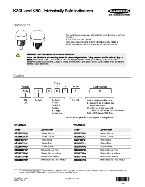
DatasheetFor use in hazardous areas with suitable zener barriers or galvanic isolatorsATEX, CSA c/us, and IECExFully sealed and rated to IEC IP67/IP69K per DIN 40050-91-, 2-, or 3-color models available with 5 available colorsWARNING: Not To Be Used for Personnel ProtectionNever use this device as a sensing device for personnel protection. Doing so could lead to serious injury or death. This device does not include the self-checking redundant circuitry necessary to allow its use inpersonnel safety applications. A sensor failure or malfunction can cause either an energized or de-energized sensor output condition.ModelsR = Red Y = Yellow B = Blue W = White X = Not UsedColor2Input Q = Integral 4-pin M12/Euro-style Quick Disconnect*QP = 150 mm (5.9 in) cable with4-pin M12/Euro-style Quick Disconnect W/XX = XX ft. Integral PVC Cable13*Models with a quick disconnect require a mating cordsetK50LK30L Models K50L Modelssuffix "Q" with "QP" in the model number. For example, K50LIGXXPQP. Models with a quick disconnect require a mating cordset.K30L and K50L Intrinsically Safe IndicatorsOriginal Document 172445 Rev. D22 September 2020172445Wiring Diagram+_Wiring Key 1 = Brown 2 = White 3 = Blue 4 = Black Color Key C1 = Color 1C2 = Color 2C3 = Color 3PinoutSee Configuration section for hazardous area wiring and installation notes.Configuration_66nF 0.56µF 1.82µF 35µH140µH280µHOne Color ConfigurationNon-Hazardous Location Hazardous Location I.S. Barrier Installation Notes1. Safety parameters are as follows:Ui/Vmax = 30V Ii/Imax = 1APi = 3.4W (Ta = -40 ˚C to +40 ˚C)Pi = 2.8W (Ta = -40 ˚C to +50 ˚C)Ci = 0Li = 02. Choose approved barriers such that the following conditions are met with all barriers combinedUi / Vmax ≥ Uo / Voc Ii / Imax ≥ Io / Isc Pi / Pmax ≥ PoCo / Ca ≥ Ci + Ccable Lo /La ≥ Li + Lcable3. Install I.S. barriers inaccordance with manufacturers instructions and local codes4. Suggested I.S. barriers are as follows MTL 7715+ (15V/100Ω)MTL 7715P+ (15V/50 Ω)Turck MZB15PX (15V/50 Ω)Ccable LcableIICIIBIIAFigure 1. Control Drawing 1-Color Configuration - Tel: + 1 888 373 6767P/N 172445 Rev. D66nF 0.56µF 1.82µF 35µH140µH280µH_Two Color ConfigurationI.S. Barrier Installation NotesK30/K50Flying Lead or Quick Disconnect Models1. Safety Parameters are as follows:Ui / Vmax = 30V Ii / Imax = 1APi = 3.4W (Ta = -40˚C to +40˚C)Pi = 2.8W (Ta = -40˚C to +50˚C)Ci = 0Li = 02. Choose approved barriers such that the following conditions are met with all barriers combinedUi / Vmax ≥ Uo / Voc Ii / Imax ≥ Io / Isc Pi / Pmax ≥ PoCo / Ca ≥ Ci + Ccable Lo /La ≥ Li + Lcable3. Install I.S. barriers inaccordance with manufacturers instructions and local codes4. Suggested I.S. barriers are as follows MTL 7715+ (15V/100Ω)MTL 7715P+ (15V/50 Ω)Turck MZB15PX (15V/50 Ω)IIAIIBIICCcable LcableFigure 2. Control Drawing 2-Color Configuration_66nF 0.56µF 1.82µF 35µH140µH280µHThree Color ConfigurationK30/K50Flying Lead or Quick Disconnect Models1. Safety Parameters are as follows:Ui / Vmax = 30V Ii / Imax = 1APi = 3.4W (Ta = -40˚C to +40˚C)Pi = 2.8W (Ta = -40˚C to +50˚C)Ci = 0Li = 02. Choose approved barriers such that the following conditions are met with all barriers combinedUi / Vmax ≥ Uo / Voc Ii / Imax ≥ Io / Isc Pi / Pmax ≥ PoCo / Ca ≥ Ci + Ccable Lo /La ≥ Li + Lcable3. Install I.S. barriers inaccordance with manufacturers instructions and local codes4. Suggested I.S. barriers are as follows MTL 7715+ (15V/100Ω)MTL 7715P+ (15V/50 Ω)Turck MZB15PX (15V/50 Ω)IIAIIBIICCcable LcableFigure 3. Control Drawing 3-Color ConfigurationGeneral Notes and Conditions for Safe Use1.The dust rating of enclosures/panels may be invalidated by the installation of the EZ-LIGHT(s). The installation of the EZ-LIGHT(s) in a particular enclosure/panel is subject to the evaluation/acceptance of the applicable approval agency.P/N 172445 Rev. D - Tel: + 1 888 373 676732.The user has the responsibility to ensure that all local, state, and national laws, rules, codes, or regulations relating to theinstallation and use of this Banner device in any particular application are satisfied. This Banner device must be installed by Qualified Persons2, in accordance with this document and applicable regulations.3.Do not attempt any repairs to this Banner device; it contains no field-replaceable parts or components.4.The nonconducting materials of this device may be susceptible to ignition-capable level of electrostatic charging andprecautions must be taken to avoid this. The user/installer shall ensure that the equipment is not installed in a locationwhere it may be subjected to external conditions (such as high-pressure steam) which are conducive to creating a build-up of electrostatic charges.5.If the equipment is likely to come into contact with aggressive substances3, then it is the responsibility of the user to takesuitable precautions4 that prevent it from being adversely affected, thus ensuring that the type of protection is notcompromised.6.Clean with a damp cloth only.7.For indicators with multiple colors, only one color is intended to be on at a time.8.When more than one intrinsically safe supply (e.g. two or three barriers) is connected to an LED indicator (input) thecombined electrical parameters of the supply must remain intrinsically safe.SpecificationsSupply Voltage and CurrentSee Configuration for safety parametersIndicatorsEntire translucent diffuser or dome provides indication. LEDs areindependently selected: Green, Red, or Amber; 2 or 3 colors, depending on model. For other colors/combinations, contact Banner Engineering foravailability.Environmental RatingIEC IP67/IEC IP69KApprovalsCSA-c/usGas and Vapors: Class I Zone 0 AEx/Ex ia IIC T4 Ga / Class I Div 1 Groups ABCDDust: Class II Zone 20 AEx/Ex ia IIIC T130°C Da / Class II Div 1 Groups EFG, Class III Div 1CSA 14.2679646ATEX/IECExGas and Vapors: II 1 G Ex ia IIC T4 Ga (Group IIC Zone 0)Dust: II 1 D Ex ia IIIC T130°C Da (Group IIIC Zone 20)Mines: I M1 Ex ia I Ma (Methane)Sira 13ATEX2058XIECEx Sir 13.0020X ConstructionBase: polycarbonateTranslucent dome: polycarbonateConnectionsMaximum cable length 29 m per parameters list in Figure 1 on p. 2, Figure 2 on p. 3, and Figure 3 on p. 3.K30: 2 m (6.5 ft) PVC integral cable, or 150 mm (5.9 in) PVC cable with 4-pin M12/Euro quick disconnectK50: 4-pin M12/Euro integral quick disconnect, 2 m (6.5 ft) PVC integral cable, or 150 mm (5.9 in) PVC cable with 4-pin M12/Euro quick disconnect Operating ConditionsPi = 2.8W: Ta = –40 °C to +50 °C (–40 °F to +122 °F)Pi = 3.4W: Ta = –40 °C to +40 °C (–40 °F to +104 °F)See figures 1, 2, and 3Certifications2809IEC IECEx SIR 13.0020XATEX Sira 13ATEX2058XCSA CoC 2679646certification of professional training, or who, by extensive knowledge, training and experience, has successfully demonstrated the ability to solve problems relating to the subject matter and work.3Aggressive substances—for example, acidic liquids or gases that may attack metals, or solvents that may affect polymeric materials.4Suitable precaution—for example, regular checks as part of routine inspections or establishing from the materials data sheet that it is resistant to specific chemicals. - Tel: + 1 888 373 6767P/N 172445 Rev. DDimensionsK30L Cabled ModelsK50L Quick Disconnect ModelsM30 x 1.5(mounting nutincluded) Max. Torque 4.5 Nm(40 in-lbf)K50L Cabled ModelsAccessoriesCordsetsP/N 172445 Rev. D - Tel: + 1 888 373 67675Banner Engineering Corp. Limited WarrantyBanner Engineering Corp. warrants its products to be free from defects in material and workmanship for one year following the date of shipment. Banner Engineering Corp. will repair or replace, free of charge, any product of its manufacture which, at the time it is returned to the factory, is found to have been defective during the warranty period. This warranty does not cover damage or liability for misuse, abuse, or the improper application or installation of the Banner product.THIS LIMITED WARRANTY IS EXCLUSIVE AND IN LIEU OF ALL OTHER WARRANTIES WHETHER EXPRESS OR IMPLIED (INCLUDING, WITHOUT LIMITATION, ANY WARRANTY OF MERCHANTABILITY OR FITNESS FOR A PARTICULAR PURPOSE), AND WHETHER ARISING UNDER COURSE OF PERFORMANCE, COURSE OF DEALING OR TRADE USAGE. This Warranty is exclusive and limited to repair or, at the discretion of Banner Engineering Corp., replacement. IN NO EVENT SHALL BANNER ENGINEERING CORP. BE LIABLE TO BUYER OR ANY OTHER PERSON OR ENTITY FOR ANY EXTRA COSTS, EXPENSES, LOSSES, LOSS OF PROFITS, OR ANY INCIDENTAL, CONSEQUENTIAL OR SPECIAL DAMAGES RESULTING FROM ANY PRODUCT DEFECT OR FROM THE USE OR INABILITY TO USE THE PRODUCT, WHETHER ARISING IN CONTRACT OR WARRANTY, STATUTE, TORT, STRICT LIABILITY, NEGLIGENCE, OR OTHERWISE.Banner Engineering Corp. reserves the right to change, modify or improve the design of the product without assuming any obligations or liabilities relating to any product previously manufactured by Banner Engineering Corp. Any misuse, abuse, or improper application or installation of this product or use of the product for personal protection applications when the product is identified as not intended for such purposes will void the product warranty. Any modifications to this product without prior express approval by Banner Engineering Corp will void the product warranties. All specifications published in this document are subject to change; Banner reserves the right to modify product specifications or update documentation at any time. Specifications and product information in English supersede that which is provided in any other language. For the most recent version of any documentation, refer to: .For patent information, see /patents.© Banner Engineering Corp. All rights reserved。
产品说明书样本(英文版)
The first summarizeToday,internal sample of liquid dielectric in the oiltank is performed by ISO3170(GB/T4756-1998)《Petrol liquid product handicraft sample law》.It is impossibly to control accurately sample ually the sample will not be exact.Performing personnels will feel tired as usual because of hardwork.When rain or snow,climb oiltank that is a very dangerous job.When getting a sample at top of oiltank,easily volatile and noxious dielectric will injure someones,at one time,it will not be in favour of environment and the medium of oiltank will be polluted by other things from environment.For solving these problem, we have developed ” The auto control getting sample from oiltank” that according to 《ISO3170(GB/T4756-1998 criterion》,it has achieved that liquid sample at different level of oiltank will be sampled. The machine operation is very simply、very accurate、excellently repeated,it’s structure is simple and it will be install very easily. It will not pollute the environment too. The sample machine has been awarded nationalpatent and the second prize of the sino petrol & chemical industry automation vocation 2010 year. The auto co ntrol getting sample from oiltank , it’s structure is sample, it will be install very easily、it’soperation is very simply、very accurate and it will not pollute the environment. At present, it’s technology has been take the lead in the like product.We have gotten by the auto control getting sample from oiltank the patents and the credits that are:( 1 ) The liquid sample devicment from oiltank, the number of parent is ZL 02208233.6.( 2 ) The liquid sample from oiltank Multilayer frame means expansion of type of zero gravity, the number of parent is ZL 200820029965.3( 3 )The sample devicment of Multi-dimensional sampling valve, the number of parent is ZL 200620079363.X( 4 )The multichannel two globe valves, the number of parent is ZL 200720032338.0( 5 ) The nationalpatent and the second prize of the sino petrol & chemical industry automation vocation 2010 yearPatentee’s declaration:About the patents of oil tank sampler:( 1 ) The liquid sample devicment from oiltank, the number of parent is ZL 02208233.6.( 2 ) The liquid sample from oiltank Multilayer frame means expansion of type of zero gravity, the number of parent is ZL 200820029965.3( 3 )The sample devicment of Multi-dimensional sampling valve, the number of parent is ZL 200620079363.X( 4 )The multichannel two globe valves, the number of parentis ZL 200720032338.0The 4 items’s using right has been awarded to Lan zhou GuKe chemical plant & apparatus Co.,Ltd by patentee for manufacture and sale. If others will manufacture and sell them ,they will break the law, the patentee will inquire their responsibilityof law and call for economics compensation.The patentee’s signature:The designsketch in fact:The second sampler technology parameter:item parameterCarried standard ISO3170 GB/T 4756-1998《The petroleum liquid handicraft sample method》The third type of sampleThe fourth applicable rangeThe self-tuning oil tank sampler is applicable to liquid medium of oiltank in the petroleum and chemical industry and so on.(for example:gas、kerosene、diesel、white oil、naphtha、crude oil、all kinds of residuum、slops、asphalt、petroleum aromatics、various solvent、thick vitriol、organic acid、lye、beer and so on)’s upper sample、middles ample、lower sample、upper middles lowe’s 1:1:1 uniform combination sample and bottoms ample、exits samples、upper sample and so on.Setting sample at the especial location by users’s require.Can setting 9 point for maxize.The fiveth The self-tuning oil tank sampler’s characteristic and virtue1.Accurate sample locationThe sampler uses the patent technology” The liquid sample from oiltank Multilayer frame means expansion of type of zero gravity, the number of parent is ZL 200820029965.3”.We establish the database of multilayer frame means expansion manufacture parameter by more and more test. We can assure that our multilayer frame means expansion can conquerconnatural weak pointthat can not go up anddown in ratio ofequality by others.Assure every sample connection that been set in multilayer frame means expansion can automatically go up and down in ratio of equality with liquid level, to let it to truely get upper sample、middles ample、lower sample、upper middles lowe’s 1:1:1 uniform combination sample. If multilayer frame means expansion can go up and down in ratio of equality that will decide every connection’s definition of sample.For the drawing-1:the drawing-12. Independence of sample mediumThe sampler uses the patent technology” The sample devicment of Multi-dimensional sampling valve, the numberof parent is ZL 200620079363.X” that is independent shunting plant of multilayer sample in the valve. It can take sample of every location independently shunt to lofting valve and can mix upper sample、middles ample、lower sample by the rate of 1:1:1 and take it to lofting valve, sample personnel can get every independent sample and 1:1:1 uniform combination sample from lofting valve exit.3、Security and reliabilityA) The self-tuning oil tank sampler uses the patent technology” The multichannel two globe valves, the number of parent is ZL 200720032338.0”that can fast cut off the communication of guitar pipe and pipe of outside, make sure that mediu m of oiltank will not leak out.The globe valves’s button run reliably and accurately, it’s operation is simple and convenientB) The sampler only need be operated on the ground, and operationer need not climb to the top of oiltank to sample. Eliminate the danger of climbing in the rain or snow. Eliminate the danger when getting a sample at top of oiltank,easily volatile and noxious dielectric will injure someones. Take humanized and reliable environmental sample come true.4.Reasonable structure and simple operationThe sampler uses the patent technology” The sample devicment of Multi-dimensional sampling valve, the number of parent is ZL 200620079363.X”that take multilayer sample oil pipes scientifically and possibly combine into one of circular operation hand-actuated wheel. Operate the rated hand-actuated wheel to choice sample point. Take complex operation process to simple action.For drawing-2Drawing-25.Hes-cling structure and little leaking pointScience and reasonable The self-tuning oil tank sampler structure, Can the DuoGe sampling output line and a circulation return pipe road high oil chips in cluster. Make DuoGe independent sample line compact from a took over, the output to tank through within the operation of the DuoWei sampling valve ,This compact structure tell the DuoGe lofting, thus greatly reducing valve sealing the number of points. In normal conditions using zero leakage .For drawing-3For drawing-36.Sample pipe road has reverse wash function:The self-tuning oil tank sampler take SKC-HF structure circulating pump But through the cycle of the pump valve or reverse rotation oil change realize tank Sample pipe road, reverse through media Thus will CaiYangGuan way or tank sampling injector mesh on the plugging of dirt reverse wash to tanks, at any time to sampling the pipeline the cleaning 7.Replacement old way of the operation is simple:The self-tuning oil tank sampler used specially developed for sampling convenient and special two tee lofting valve, Made with a conversion between lofting cycle is very simple, just press the valve for the arrows spin an Angle start after circulating pump can.8.Convenient installation:The sampler can be set up special steam heating device, oil tank external sampler components have straight heat conduction heat tracing of. For drawing-4 Use electric heating, in the valve body sampler exclusively electric tracing band through the heating channel, the heating effect ideal. A heating device can be used for the sampler asphalt, and so easy as the medium tank.For drawing-49. Meet of the medium to samplingThe sampler can be set up special steam heating device, oil tank external sampler omponents have straight heat conduction heat tracing of. Use electric heating, in the valve body sampler exclusively electric tracing band through the heating channel, the heating effect ideal. A heating device can be used for the sampler asphalt, and so easy as the medium tank.The sixth. T he self-tuning the composition of the oil tank sampler The self-tuning oil tank sampler The composition of the oil tank sampler as shown in figure 5 shows1, extendable frame; 2, float group; 3, circulating pump 【 manual pump, pneumatic pump 】; 4, sampling combination tube; 5, sampling distribution device; 6, the integrated oil, a choice of the directional control valve, valve, sample combination distribution on a stop valve, no drop leak lofting valve combination together; 7, operation box; 8, adjustable bearing; under the plane 9,small tube resistance metal hoseFor drawing-5The seventh. working principleThe self-tuning oil tank sampler is through the float group in the expansion set drive tank with oil level within the truss and sample, the upper or lower, middle kind, samples and top samples (optional) sampling mouth all fixed in telescopic rack, telescopic frame in liquid is according to the proportion of sampling, ensure that came out of the position accuracy. The sampling location is determined according to the ISO3170 (GB/T4755 1998) "oil liquid product manual sampling method" regulation of sampling location of the design. For drawing-6 showsFor drawing-6Different sample position of the pipeline is independent sample through sampling combination tube transfer to oil chips, again through the DuoWei reversing valve handwheel control of their respective independent leads to the valve, again by lofting lofting valve control lofting or cycle will turn to cycle the valve, start lofting circulation pump can turn number after the part of the old way of pipeline to the bottom of the tank replacement cycle; And then the valve position to rotate lofting lofting, can get the export of lofting valve in the tank is a positionof the sample. Repeat the above。
WEG中高压电机选型样本
电机|自动化|能源|油漆中高压电机三相异步电机M 系列-主系列M 系列电机根据冷却方式和防护等级的不同,具有不同的配置;这样的设计及配置可确保电机更好地符合工作环境条件的要求。
在巴西,机座大小IEC 280至450(NEMA 4400至8000)的电机的机座为铸铁材料;而机座大小IEC 500(NEMA8800)及机座尺寸更大的电机的机座由钢板焊接而成。
WEG M 系列电机使用的优势包括:⏹高效率⏹防护等级IP23(WP-I)、IP24(W)(WP-II)或IP55(W)/IP56(W)/IP65(W)⏹噪声水平低⏹维护成本低,维护方便⏹可按API 541标准制造⏹鼠笼转子滑环(绕线转子)⏹轴承油润滑滑动轴承油脂或油润滑滚珠或滚柱轴承⏹与原有电机的互换性电机描述术语IEC (S,M,L,A,B,C,D,E)NEMA (06,07,08,09,10,11...)额定输出值至50,000kW (70,000HP)电压范围220至13,800V 速度范围3600至300转/分H 系列–紧凑型H 系列电机结构简单紧凑,由于其可靠性高被广泛地应用,适合驱动各行业的大多数机械设备。
这种电机的机座由高强度铸铁铸造而成,外置冷却散热筋。
由内外气流装置构成的整个冷却系统在机座的内部均匀地供给冷却空气,使电机的性能达到最佳。
WEG H 系列电机使用的优势包括:⏹高效率⏹防护等级:IP(W)55/IP(W)56/IP(W)65(TEFC 、TEBV)⏹低噪声水平⏹维护成本低,维护方便⏹耐用的高强度铸铁结构可按IEEE841(2001)的耐磨及耐化学品的标准制造可按API541标准制造⏹轴承油润滑滑动轴承油脂或油润滑滚珠或滚柱轴承⏹冷却自冷却强制冷却,通常为变频应用⏹与原有电机的互换性⏹内部空气流动⏹无需冷却器电机描述术语额定输出值100至3,150kW (135至4000HP)电机范围220至11,000V 速度范围3600至600转/分NEMA (06,07,08,09,10,11...)应用鼠笼式电机H和M系列电机由于其多功能的设计和优越的操作性能而被广泛地使用于各行各业。
SIEMENS SITRANS FC 科里奥利质量流量计 说明书
SITRANS F C科里奥利质量流量计产品样本•2010SITRANS F CAnswers for industry.SITRANS F CMASSFLO ҅ ε2■̩ SITRANS F C MASSFLOӎă Lj Ă Lj Ă ă■•• Lj Վ• Վ Lj ҾMASSFLO ӎ SENSORPROM LjՔ Վ ă Lj Պ ăSENSORPROM Lj ԥ SENSORPROM ă• Lj • Վ Lj ă Lj SENSORPROM ăUSM II Đ đ Lj Lj ԍ Ս / ă■ӎ ă Ă Ă Ă Lj ք Վ Ljփ ăҾ Lj Ԣ ԲLj ăԻʮͲ ѳͲ ͙ MASS 6000 IP67 ḅӃ9 MASS 2100 DI 1.528 FC300 DN 432 MASS 2100 DI 3 ~ 4036 MASS MC2 DN 50 ~ 15046 MASS MC2-Ex DN 50 ~ 15046MASS MC2 DN 20 ~ 8046MASS 6000 19”13 MASS 2100 DI 1.528 FC300 DN 432 MASS 2100 DI 3 ~4036 MASS MC2 DN 50 ~ 15046 MASS MC2-Ex DN 50 ~ 15046MASS MC2 DN 20 ~ 8046MASS 6000 Ex 19”13 MASS 2100-Ex DI 1.528 FC300 DN 432MASS 2100-Ex DI 3 ~ 4036MASS 6000 Ex-d փ20 MASS 2100-Ex DI 1.528 FC300 DN 432 MASS 2100-Ex DI 3 ~ 4036 MASS MC2 DN 50 ~ 15046MASS MC2 DN 20 ~ 8046SIFLOWFC070Ք / Ԗ24 և28҅ ˗ ˿̺ʵ ˁ ⅳӝ ҋ Lj Lj Lj LjLj Lj Lj Lj (Plato/Brix)Lj Lj LjCO 2 Lj CIP- ˁ ԭ Lj Lj Lj ˁ Lj LjCNG Lj LjLPG质量流量计SITRANS F CMASSFLO 科里奥利质量流量计系统信息3参见网上的Product Selector /its_main_en.asp某些特性会有一些制约条件MASS 2100DI 1.5MASS 2100DI 3 ~ 40FC300DN 4MC2DN 50 ~ 150MC2卫生型DN25 ~ 80MASS6000IP67MASS600019“MASS 6000Ex d SIFLOW FC070标准型/防爆型7ME41007ME4100, 7ME4200, 7ME42107ME44007ME43007ME43107ME41107ME41107ME41107ME4120结构一体式分体式变送器外壳聚酰胺 IP67/NEMA4XNoryl (SIMATIC S7-300), IP20/NEMA2不锈钢 IP67/NEMA4X19" 架装型 IP20/NEMA2 铝 盘后安装型 IP20/NEMA2 铝 墙装型IP66/NEMA4 ABS 塑料盘前安装型 IP66/NEMA4 ABS 塑料通讯HARTPROFIBUS PAPROFIBUS DPMODBUS RTU / RS 485 MODBUS RTU / RS 232FOUNDATION Fieldbus H1DeviceNet供电电压24V DC24 V AC/DC115/230 V AC口径DI 1.5 (1/16")DI 3 (1/8")DN 4 (1/6")DI 6 (1/4") DI 15 (1/2") DN 20 (3/4") DI 25 (1") DI 40 (1½")DN 50 (2") DN 65 (2½") DN 80 (3")DN 100 (4") DN 150 (6")过程连接标准和压力管螺纹NPT ANSI/ASME B.20.1;PN 100 ISO 228/1; PN 100法兰EN 1092-1 PN 40 EN 1092-1 PN 100 1)ANSI B16.5 Class 150ANSI B16.5 Class 300 ANSI B16.5 Class 600 1)卫生型DIN 11851 PN 25 1)DIN 11851 PN 40 DIN 11864-2A卡箍 ISO 2852 PN 16 ISO 2853 PN 16DIN 32676 Tri-Clamp 三爪卡箍PN 10/PN 16其它需求● = 提供1)口径DN 150 的传感器不提供SITRANS F CMASSFLO ҅ ε4փ 1.4435 (316L)z z zzփ 1.4571 (316 Ti)zC - 22zzzC - 4zͤ ևU zԚұ PN 10zPN 16z z PN 25z z PN 40zz zPN 100z z z z 1)2)z z zd 0.1% z zzd 0.15% z z d 0.001 g/cm3zzzd 0.0015 g/cm3z 3)zd 0.0005 g/cm 3zՀPG 13.5z½“ NPT z z z M20zzzzz =1) DN100 DN150 փ 2) 3)DI 3 DI 6Ԯ ʴ Product Selector/its_main_en.asp̈ ͕ ʮ̈ҋ ̓MASS 2100DI 1.5MASS 2100DI 3 ~ 40FC300DN 4MC2DN 50 ~ 150MC2 ԉ DN 25 ~ 80MASS 6000IP67MASS 600019“MASS 6000Ex d SIFLOW FC070 ѕ / 7ME41007ME4100, 7ME4200, 7ME42107ME44007ME43007ME43107ME41107ME41107ME41107ME41201)2)3)质量流量计SITRANS F CMASSFLO 科里奥利质量流量计系统信息5防爆认证危险区域Ex II 1GEEx ia IIC T3(T4) ~ T6ATEX ●●Class 1, Div 1, Group A,B,C, DClass I, Zone 0, Aex iaIIC T3 ~ T6Class I, Zone 0, Ex ia IIC T3 ~ T6C-UL●1)●1)Ex ia IIC T3/T4 ~ T6ATEX ●Class I, Div 1, Group A,B,C,DClass I, Zone 0, Ex ia IIC T3 ~ T6C-UL●Class 1, Div 2, Groups A,B,C,DClass I, Zone 2, Aex nC IIC T4Class I, Zone 2, Ex nC [nL] IIC T4C-UL●2)Ex II (1)G [EEx ia] IICATEX ●Class I, Division 1 & 2,Groups A,B,C,DClass 1, Zone 2 & Zone 0, Aex nC [ia] IIC T4Class 1, Zone 2 & Zone 0, Ex nC [ia] IIC T4C-UL●3)Ex II 2GEEx d e [ia/ib] IIC T6ATEX ●Ex II (1)G [Ex ia] IIC Ex II 3G Ex nA II T4ATEX ●4)5)Ex nA [ia] IIC T4IECEx ●5)Ex nA [ia] IIC T4Class I, Zone 2, Aex nA [ia] IIC T4uCSAus●5)非防爆区域USL, CNL 流量计C-UL ●2)USR, CNR 流量计C-UL ●6)USR, CNR 流量计C-UL ●7)USL, CNL 流量计C-UL ●8)PED 认证Fluid group 1Category II, Module H PEDDirective 97/23/EC ●9)Module B1 + D 0/25 ~ 100 bar,-80/200ºC, DN 20 ~150PEDDirective 97/23/EC ●●CRN 认证Category F OF10769.5C CRN●●●医药领域EHEDGTUM ●●● = 提供注意:安全使用的一些特殊条件,可能在认证或操作手册中已说明。
工厂检验报告样本CIG
CIG 023Factory InspectionReport ChineseUL does not endorse any vendors or products referenced herein.UNDERWRITERS LABORATORIES INC. ASSUMES NO RESPONSIBILITY FOR ANY OMISSIONS OR ERRORS ORINACCURACIES WITH RESPECT TO THIS INFORMATION. UL MAKES NO REPRESENTATION OR WARRANTY OF ANY KIND WHATSOEVER, WHETHER EXPRESS OR IMPLIED, WITH RESPECT TO THE ACCURACY, CONDITION, QUALITY, DESCRIPTION, OR SUITABILITY OF THIS INFORMATION, INCLUDING ANY WARRANTY OF MERCHANTABILITY OR FITNESS FOR A PARTICULAR PURPOSE AND EXPRESSLY DISCLAIMS THE SAME.Copyright Underwriters Laboratories Inc. All rights reserved. May not be reproduced without permission. This document isWARNING:THIS DOCUMENT IS ONLY VALID IF USED BY ECS MEMBERSAND THEIR AUTHORISED AGENTSPERMANENT DOCUMENT 永久性文件CIG 023Factory Inspection Report 工厂检验报告WARNING:THIS DOCUMENT IS ONLY VALID IF USED BY ECS MEMBERSAND THEIR AUTHORISED AGENTS警告:本文件仅在为欧洲认证体系(ECS)成员及其授权代理人所用时生效Approved by: ECS General Meeting, 22/23-04-2009 Nr of pages: 19 Date of issue: May 2009Supersedes: PD CIG 023 - June 2004 Page 1 of 19 PD CIG 023 reports shall not contain any unauthorised modifications which change the originalmeaning or the requirements.Any additions created to any document in the series shall be shown in an Appendix.未经批准,不得对 PD CIG 023 报告进行任何改变其原有含意或要求的修改。