Ballscrew 滚珠丝杆
基于螺旋线铣削大导程滚珠丝杠的应用

基于螺旋线铣削大导程滚珠丝杠的应用概述滚珠丝杠(Ball Screw)是一种传动机构,它通过滚珠在导程内滚动来实现转动或者移动,具有高精度、高效率、长寿命、低摩擦、低噪音等优点,因此在机床、数控机床、自动化生产线等领域得到广泛应用。
对于大导程滚珠丝杠的加工,常规的滚珠丝杠铣削工艺存在一些问题,例如加工效率低、钢丝卡断、加工后的表面粗糙度等问题。
为了解决这些问题,一些厂家开始使用一种基于螺旋线铣削大导程滚珠丝杠的新工艺,该工艺不仅能够提高加工效率和表面粗糙度,还可以保证滚珠丝杠加工的准确度和稳定性。
本文将对基于螺旋线铣削大导程滚珠丝杠的应用进行介绍,并对其优缺点进行分析。
基于螺旋线铣削大导程滚珠丝杠的工艺流程基于螺旋线铣削大导程滚珠丝杠的加工流程如下所示:1.预切削:首先对滚珠丝杠外壳进行预切削,预切削的目的是为了减小加工后的表面粗糙度和提高加工效率。
2.段铣:将滚珠丝杠放在机床上进行段铣加工,将丝杠的每段铣成一定角度的螺旋线,直到整个丝杠的螺旋线被铣制完成。
3.加工螺母座:将滚珠丝杠放到机床上,使用刀具将螺母座进行加工。
4.打磨:将加工后的滚珠丝杠放到砂带机上进行打磨,达到所要求的精度和表面粗糙度。
通过以上工艺流程,可以制造出高精度、高效率、长寿命、低摩擦、低噪音的大导程滚珠丝杠。
基于螺旋线铣削大导程滚珠丝杠的优缺点优点1.加工效率高:基于螺旋线铣削大导程滚珠丝杠的工艺可以实现快速加工,大幅提高加工效率。
2.表面粗糙度低:由于螺旋线铣削工艺的特点,加工后的表面粗糙度较低,不需要进一步的打磨加工。
3.加工稳定性好:由于加工过程中使用合适的加工参数,使得加工过程稳定性较高,能够准确地控制加工误差。
4.切削力小:由于采用螺旋线铣削工艺,切削力较小,材料切削时不易断裂或变形,确保加工精度。
缺点1.设备要求高:采用螺旋线铣削工艺需要使用特殊的加工设备,因此成本会稍微高一些。
2.软件要求高:采用螺旋线铣削工艺需要使用特殊的加工软件,对操作者的技术水平和专业知识要求较高。
滚珠导螺杆

Integrity
Teamwork
Innovation
Learning Responsibility
Integrity
Teamwork
Innovation
Learning Responsibility
Integrity
Teamwork
Innovation
Learning Responsibility
Integrity
Teamwork
Innovation
Learning Responsibility
Integrity
Teamwork
Innovation
Learning Responsibility
滾珠導螺桿固定端尾部偏擺量(Run out)常是判斷組裝品質的 指標之一。若零件精度都良好,此處的偏擺應可調校至0.01mm 以內。 設計上,螺帽(Lock nut)鎖緊後,螺桿應還可看到2~3牙,如 此螺帽的鎖緊力方能確保。
螺帽
螺帽是影響滾珠導螺桿品質最重要的因素
螺帽內部滾珠滾動道的加工相當困難,滾珠導螺 桿的精度、噪音(運轉順暢度)、壽命均與螺帽有 重大關係。
Integrity
Teamwork
Innovation
Learning Responsibility
組裝
所有零件都加工良好,接著是組裝。
滾珠(Ball)的尺寸必須經過仔細篩選,大 小盡量一致,一般滾珠的直徑誤差都要求 在5m以內,如此滾珠才可平均受力。不同 直徑的滾珠導螺桿,滾珠的尺寸亦不同。
Integrity
Teamwork
Innovation
Learning Responsibility
螺桿
螺桿通常由德、日等國進口高級鋼胚, 加工程序大致如下:
NSK滚珠丝杠规格参数英文版
Press machine
Ejector axial drive Mold clamp force of 500t and over: HTF-SRC+A1 seal Mold clamp force under 500t: Horizontal ball screws for ejectors
For plasticating movement axial drive Horizontal ball screws for ejector
Press part
HTF-SRE HTF-SRC+A1 seal HTF-SRD+A1 seal
Die cushion part
HTF-SRD+A1 seal
3
Technical Description
2 Features
NSK high-load drive ball screws have maximized the ball diameter and increased the number of valid load balls for a design that can withstand a high load. They have achieved a high reliability through many different technologies including even load distribution. Technology for high-speed feeding and preserving the work environment have also been added to accommodate the needs of various devices requiring a large load and high reliability, such as hydraulic cylinder repla large machinery.
轧制滚珠丝杆工艺流程

轧制滚珠丝杆工艺流程## English Answer ##。
1. Raw Material Preparation.The first step in the manufacturing process of rolled ball screws is the preparation of the raw materials, typically steel bars. These bars are cut to the desired length and then subjected to a series of processes, including:Annealing: The steel bars are heated to a high temperature and then slowly cooled to achieve a specific hardness and strength, usually between 28-34 HRC.Centerless grinding: The bars are ground to a precise diameter to remove any imperfections and ensure a consistent surface finish.2. Thread Rolling.The prepared steel bars are then subjected to thread rolling, a process that forms the threads on the screw by cold-working the material. This involves passing the bars through a set of hardened steel rolls that have the desired thread profile. The rolling action causes the material to deform and flow, creating the threads.3. Heat Treatment.After thread rolling, the ball screws undergo heat treatment to improve their mechanical properties, such as hardenability, wear resistance, and fatigue strength. This typically involves the following steps:Carburizing: The ball screws are heated in a carbon-rich atmosphere, causing carbon to diffuse into the surface of the steel, creating a hard, wear-resistant layer.Hardening and tempering: The ball screws are heated to a high temperature (typically above 800°C) and thenrapidly cooled to form martensite, a hard and brittlemicrostructure. The screws are then tempered at a lower temperature to relieve internal stresses and improve toughness.4. Grinding.After heat treatment, the ball screws are subjected to grinding to achieve a high level of precision and surface finish. This involves two main steps:Cylindrical grinding: The outer diameter of the screw is ground to a precise tolerance, ensuring concentricity and dimensional accuracy.Thread grinding: The threads are ground to the desired profile, shape, and surface finish. This step is critical for ensuring smooth and accurate movement of the ball bearings along the screw.5. Deburring and Cleaning.The ground ball screws are then deburred and cleaned toremove any burrs or contaminants that may interfere with the performance of the screws. This involves using avariety of methods, such as tumbling, shot blasting, or ultrasonic cleaning.6. Assembly and Inspection.The final step is to assemble the ball screws with the ball bearings and nuts. The bearings are typically preloaded into the screw and nut to minimize backlash and ensure smooth operation. The assembled ball screws are then inspected to ensure they meet the specified tolerances and performance requirements.## Chinese Answer ##。
PMI滚珠螺杆精密级型号对照表

65
86
65
61
66 64 98 16 82 36 72 20 9 14 8.5 PT1/8" 76
4
3 10 6.35
4
12 6.35
3
5 3.175
4
8 4.762
4
36
3
2330 2605 3340 2605 1490 2530
5640 5310 7080 5310 4690 6630
77
80
Dg6 L A T W G H S X Y Z
kgf/ Q
Ca(動負荷)Co(靜負荷)
μm
螺桿尺寸
net 外徑 導程
鋼珠 直徑
基本額定負荷(kgf ) 螺帽 循環圈數 (1×10⁶ REV.)
Dg6 L Ca(動負荷)Co(靜負荷)
A
法蘭 T WG
配合 螺絲孔 HSXYZ
單位:mm 油孔 剛性 規格
920 1240 1650 1710 2280 2050 2730 2300 3070
A52 PMI 精密級滾珠螺桿
net forrun。 www。 金 五 一 凡
13 PMI 精密級滾珠螺桿
滾珠螺桿綜合技術型錄
Ballscrews General Catalog
A53
PMI 精密級滾珠螺桿
13.1 內循環系列
特性: 內循環構造的優點,使螺帽外徑為精巧的「圓周 型」參照圖13.1。因此適合內部空間較小的機器。 需要注意的是內循環滾珠螺桿的螺桿軸必須有一端 是完全牙,且該端的肩部直徑必須小於螺桿軸外 徑,否則無法組裝螺帽。
114
95
104
67
75
121 22 97 47 94 20 14 20 13 PT1/8"
滚珠丝杠
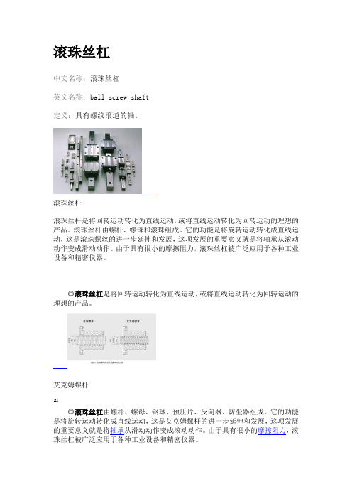
滚珠丝杠中文名称:滚珠丝杠英文名称:ball screw shaft定义:具有螺纹滚道的轴。
滚珠丝杆滚珠丝杆是将回转运动转化为直线运动,或将直线运动转化为回转运动的理想的产品。
滚珠丝杆由螺杆、螺母和滚珠组成。
它的功能是将旋转运动转化成直线运动,这是滚珠螺丝的进一步延伸和发展,这项发展的重要意义就是将轴承从滚动动作变成滑动动作。
由于具有很小的摩擦阻力,滚珠丝杠被广泛应用于各种工业设备和精密仪器。
◎滚珠丝杠是将回转运动转化为直线运动,或将直线运动转化为回转运动的理想的产品。
艾克姆螺杆[1]◎滚珠丝杠由螺杆、螺母、钢球、预压片、反向器、防尘器组成。
它的功能是将旋转运动转化成直线运动,这是艾克姆螺杆的进一步延伸和发展,这项发展的重要意义就是将轴承从滑动动作变成滚动动作。
由于具有很小的摩擦阻力,滚珠丝杠被广泛应用于各种工业设备和精密仪器。
◎滚珠丝杠是工具机和精密机械上最常使用的传动元件,其主要功能是将旋转运动转换成线性运动,或将扭矩转换成轴向反覆作用力,同时兼具高精度、可逆性和高效率的特点。
类型常用的循环方式有两种:外循环和内循环。
滚珠在循环过程中有时与丝杠脱离接触的称为外循环;始终与丝杠保持接触的称为内循环。
滚珠每一个循环闭路称为列,每个滚珠循环闭路内所含导程数称为圈数。
内循环滚珠丝杠副的每个螺母有2列、3列、4列、5列等几种,每列只有一圈;外循环每列有1.5圈、2.5圈和3.5圈等几种。
1)外循环:外循环是滚珠在循环过程结束后通过螺母外表面的螺旋槽或插管返回丝杠螺母间重新进入循环。
如图2-3所示,外循环滚珠丝杠螺母副按滚珠循环时的返回方式主要有端盖式、插管式和螺旋槽式。
图2-3 常用外循环方式(a)端盖式;(b)插管式;(c)螺旋槽式如图2-3(a)所示是端盖式,在螺母上加工一纵向孔,作为滚珠的回程通道,螺母两端的盖板上开有滚珠的回程口,滚珠由此进入回程管,形成循环。
如图2-3(b)所示为插管式,它用弯管作为返回管道,这种结构工艺性好,但是由于管道突出螺母体外,径向尺寸较大。
滚珠丝杠选型计算
=
P h0 tan with tan = d0 tan ( + " )
=
P h0 ") tan ( with than = d0 tan ( )
就速度,温度和润滑而言,理论效率会降低约 5% 。如果此负载 F 和基本动负载 C am之差在 0.5 以下,那 负载系数 f 1应进一步减小(见下图)。对于滚珠丝杠而言,在此基础上的计算效率只包括润滑,并没有 包括抽支撑的润滑环。如需要提高效率,请与 SBC 联系。
精密转造滚珠丝杠 PRECISION ROLLED BALL SCREW
寿命计算 Calculation LIfe 根据负荷计算寿命 Life as a function of load
1605( 无间隙型 Non- Backlash) 1605 1605( 间隙型 Backlash) 2002( 间隙型 Backlash) 2005( 间隙型 Backlash) 2525( 间隙型 Backlash) 2505 3205( 间隙型 Backlash) 2510 2510 3210( 间隙型 Backlash) 4005( 间隙型 Backlash) 3210 4005
精密转造滚珠丝杠 PRECISION ROLLED BALL SCREW
寿命计算 Calculation Life Mounting
额定寿命Life Expectancy 冲击负载 Load Impact 最佳条件 Optimum In case of radial loads please contact us
把转动转化为 直线运动时的 理论效率 把直线运动 转化为转动 时的理论效率
滚珠螺杆工作原理
滚珠螺杆工作原理滚珠螺杆(Ball Screw)是将滚珠把力传递到螺母的一种传动机构。
它的工作原理是利用滚球的滚动轮廓与螺杆的滚动轮廓性质,实现高精度、高效率的传动。
其优点是传动效率高、轮廓精度高、摩擦力小、能量损耗少、稳定性好,并且使用寿命长。
在现代机械制造业中得到了广泛应用。
一、滚珠螺杆的结构滚珠螺杆主要由螺纹轴、螺杆母、滚珠、保持器和端盖组成。
螺纹轴是一个左旋和右旋的螺杆,被称为有螺纹的轴心。
螺杆母是一种具有同轴度的圆柱体,中间开有螺孔,用于通过螺纹轴的转动与它结合。
滚珠是用来承载、传递力量和减少摩擦的小球体。
保持器是把滚珠按照一定方式固定在螺杆母内部的构件。
端盖是安装在滚珠螺杆的两端,防止滚珠脱落和进入灰尘、水分等。
滚珠螺杆的工作原理是利用滚珠的滚动和滑动特性,将转动运动转换成线性运动。
当有力在螺母上作用时,滚珠会顺着螺杆的螺纹轮廓向前滚动,从而带动螺母沿轴线方向移动。
因为滚珠的滚动摩擦力小,所以滚珠螺杆的转换效率高,可精准传输大量的力量和扭矩。
详细来说,当输入装置(如电机)带动螺纹轴转动时,螺纹轴带动滚珠一起向前滚动,由于滚珠的形状和螺杆池相同,所以在进入螺母后可以顺着螺杆陆廓滚动。
滚珠滚动时带动螺母向前移动,使线性运动完成。
由于滚珠的半径很小,所以在滚动时的接触面积也非常小,因此摩擦小、寿命长、精度高。
三、滚珠螺杆的分类和特点1. 根据进给方式进行分类(1)单螺杆滚珠螺杆单螺杆滚珠螺杆是最常见的一种滚珠螺杆。
它有一个螺纹蜗杆,一个螺杆母和几个滚珠。
由于它的结构简单、易于制造,成本较低,所以在一般传动系统中应用较广泛。
双螺杆滚珠螺杆由两个螺纹蜗杆、两个螺杆母和几个滚珠组成。
它的双螺旋结构使得传动更加平稳,且进给速度比单螺杆滚珠螺杆大。
外滚珠式滚珠螺杆的外壳设有几个板孔,将滚珠放入然后再将螺杆套入自由滚动的滚珠中。
其特点是传动功率大、传动效率高、寿命长、精度高、噪声小。
(2)内滚珠式滚珠螺杆内滚珠式滚珠螺杆是指滚珠放在螺杆内部,螺母将滚珠压在轨道上,保持其与螺杆的接触,实现传递动力的装置。
常用机械英语单词
常用机械英语词汇reference number:参考号,引用号(码)ball screw :滚珠丝杆linear guide:直线导轨torque:扭矩, 转矩dynamic torque:动态扭矩specification:规格Shaft diameter:轴径lead:进程ball screw lead:滚珠丝杆螺距stroke:行程nominal:标称的,额定nominal stroke:额定行程stroke limit:极限行程mounting:安装mounting hole:安装孔, 固定孔inertia:惯性, 惯量effective turns:有效匝数rating:额定basic load rating:基本额定载荷static moment:静力矩preload:预载; 预加负荷accuracy grade:准确度级别geometrical moment of inertia:几何惯性矩,断面转动惯量polar moment of inertia of area:面积惯性极矩,断面惯性极矩rail moment of inertia:转动惯量radial direction:径向rigidity:刚性, 硬度deformation:变形vertical direction:垂直方向lateral direction:横向rolling direction:轧制方向,滚动方向pitching direction:俯仰方向yawing direction:盘旋方向repeatability:可重复性, 反复性, 再现性,重复精读running:不断的, 连续的parallelism:平行度running parallelism:连续的移动平行度backlash:间隙metal cutting 金属切削machine tool机床friction 摩擦传动drive/transmission弹性elasticity频率特性frequency characteristic误差error定位allocation机床夹具jig动力学dynamic运动学kinematic静力学static分析力学analyse mechanics拉伸pulling压缩hitting剪切shear扭转twist弯曲应力bending stress强度intensity三相交流电three-phase AC磁路magnetic circles变压器transformer异步电动机asynchronous motor几何形状geometrical正弦形的sinusoid交流电路AC circuit机械加工余量machining allowance 变形力deforming force变形deformation硬度rigidity退火anneal正火normalizing脱碳decarburization渗碳carburization电路circuit半导体元件semiconductor element直流电源DC electrical source门电路gate circuit逻辑代数logic algebra外圆磨削external grinding内圆磨削internal grinding平面磨削plane grinding变速箱gearbox离合器clutch绞孔fraising绞刀reamer螺纹加工thread processing铣削mill铣刀milling cutter工件workpiece齿轮加工gear mechining进给方向direction of feed进给运动feed movement合成进给运动resultant movement of feed合成切削运动resultant movement of cutting合成切削运动方向direction of resultant movement of cutting 切削深度cutting depth前刀面rake face刀尖nose of tool前角rake angle后角clearance angle龙门刨削planing主轴spindle主轴箱headstock卡盘chuck加工中心machining center车刀lathe tool车床lathe钻削镗削bore车削turning磨床grinder基准benchmark钳工locksmith锻forge压模stamping焊weld拉床broaching machine拉孔broaching装配assembling铸造found流体动力学fluid dynamics流体力学fluid mechanics加工machining液压hydraulic pressure切线tangent机电一体化mechanotronics mechanical-electrical integration 介质medium液压驱动泵fluid clutch液压泵hydraulic pump阀门valve失效invalidation强度intensity安全系数safty factor可靠性reliability螺纹thread螺旋helix键spline销pin滚动轴承rolling bearing滑动轴承sliding bearing弹簧spring制动器arrester brake十字结联轴节crosshead联轴器coupling链chain皮带strap精加工finish machining粗加工rough machining变速箱体gearbox casing腐蚀rust氧化oxidation磨损wear耐用度durability离散信号discrete signal超声传感器ultrasonic sensor 集成电路integrate circuit挡板orifice plate残余应力residual stress套筒sleeve扭力torsion冷加工cold machining电动机electromotor汽缸cylinder过盈配合interference fit倒角rounding chamfer优化设计optimal design工业造型设计industrial moulding design有限元finite element滚齿hobbing插齿gear shaping伺服电机actuating motor铣床milling machine钻床drill machine镗床boring machine步进电机stepper motor丝杠screw rod导轨lead rail组件subassembly可编程序逻辑控制器Programmable Logic Controller PLC 电火花加工electric spark machining电火花线切割加工electrical discharge wire - cutting相图phase diagram固态相变solid state phase changes 有色金属nonferrous metal陶瓷ceramics合成纤维synthetic fibre电化学腐蚀electrochemical corrosion 车架automotive chassis悬架suspension转向器redirector变速器speed changer板料冲压sheet metal parts孔加工spot facing machining车间workshop气动夹紧pneuma lock数学模型mathematical model画法几何descriptive geometry机械制图Mechanical drawing剖视图profile chart标准件standard component零件图part drawing装配图assembly drawing尺寸标注size marking技术要求technical requirements刚度rigidity位移displacement疲劳极限fatigue limit断裂fracture塑性变形plastic distortion脆性材料brittleness material刚度准则rigidity criterion垫圈washer垫片spacer直齿圆柱齿轮straight toothed spur gear 斜齿圆柱齿轮helical-spur gear直齿锥齿轮straight bevel gear运动简图kinematic sketch齿轮齿条pinion and rack蜗杆蜗轮worm and worm gear虚约束passive constraint曲柄crank摇杆racker凸轮cams共轭曲线conjugate curve范成法generation method定义域definitional domain值域range导数\微分differential coefficient求导derivation定积分definite integral不定积分indefinite integral曲率curvature偏微分partial differential毛坯rough游标卡尺slide caliper千分尺micrometer calipers攻丝tap二阶行列式second order determinant逆矩阵inverse matrix线性方程组linear equations概率probability随机变量random variable排列组合permutation and combination气体状态方程equation of state of gas动能kinetic energy势能potential energy机械能守恒conservation of mechanical energy 动量momentum桁架truss轴线axes余子式cofactor逻辑电路logic circuit触发器flip-flop脉冲波形pulse shape数模digital analogy液压传动机构fluid drive mechanism 机械零件mechanical parts淬火冷却quench淬火hardening回火tempering调质hardening and tempering磨粒abrasive grain结合剂bonding agent砂轮grinding wheel。
机床人必知的滚珠丝杠,传动世界的关键机械部件!你真的了解吗?
机床人必知的滚珠丝杠,传动世界的关键机械部件!你真的了解吗?滚珠螺杆(Ballscrew),别名球螺杆、导螺杆,是一种钢珠介于螺帽与螺杆之间做运动,将传统螺杆之滑动接触转换成滚动接触然后再将螺帽内的钢珠回转运动转为直线运动的传动机械组件。
滚珠螺杆具有定位精度高、高寿命、低污染和可做高速正逆向的传动及变换传动等特性,因具上述特性,滚珠螺杆已成为近来精密科技产业及精密机械产业的定位及测量系统上的重要零组件之一。
滚珠螺杆主要为螺杆、螺帽、钢珠、固定座、刮刷器及回流管所构成的,依其循环系统的不同更分为外循环式、内循环式、端塞循环式滚珠螺杆。
滚珠螺杆的结构传统分为内循环结构(以圆形反向器和椭圆形反向器为代表)和外循环结构(以插管为代表)两种。
这两种结构也是最常用的结构。
这两种结构性能没有本质区别,只是内循环结构安装连接尺寸小;外循环结构安装连接尺寸大。
目前,滚珠丝杠副的结构已有10多种,但比较常用的主要有:内循环结构;外循环结构;端盖结构;盖板结构。
内循环结构反向器的形状有多种多样,但是,常用的外形就是圆形和椭圆形。
由于圆形滚珠反向通道较短,因此,在流畅性上不如椭圆形结构。
现在,最好的反向器结构为椭圆形内通道结构,由于滚珠反向不通过丝杠齿顶,类似外循环结构,因此,消除了丝杠齿顶倒角误差给滚珠反向带来的影响。
但由于制造工艺较复杂,影响了这种结构的推广。
滚珠螺杆发展至今,已经广泛应用到各产业机械的定位精度控制上如精密工具机、产业机械、电子机械、输送机械的重要主角。
NB这名字的来由自然不是自诩很NB,而是日本轴承的缩写。
以他们的SPBR为例看看滚珠轴承的组成。
图为滚珠丝杠剖面图图为滚珠丝杠剖面图图为滚珠丝杠剖面图图为HIWIN(上银科技)量产的滚珠螺杆。
发展至今,上银已成为全球占三望二的第三大滚珠螺杆、线性滑轨等精密机械业者(前两名都是日本厂商分别是日本的THK及NSK)。
图为HIWIN(上银科技)量产的滚珠螺杆。
- 1、下载文档前请自行甄别文档内容的完整性,平台不提供额外的编辑、内容补充、找答案等附加服务。
- 2、"仅部分预览"的文档,不可在线预览部分如存在完整性等问题,可反馈申请退款(可完整预览的文档不适用该条件!)。
- 3、如文档侵犯您的权益,请联系客服反馈,我们会尽快为您处理(人工客服工作时间:9:00-18:30)。
Ballscrews General Catalog
B B A A A
13
3
3.1
8 mm 100 mm 300 mm 8000 mm
3.2
3.1 3.3 3.3
12 mm 50 mm
1000 mm 5000 mm
3.1
-
3.2
-
3.3
-
14
Ballscrews General Catalog
1
1 • 2~3 • •
a.
b.
c.
6.1
fw
(V) V<15 (m/min) 15<V<60 (m/min) V>60 (m/min)
2003 2004 2005 19
2 3
8 3
1
( 2006 11 2007 2 7 7 7 2008 5 OHSAS-18001 12 8 25 DSI Barcode BSI BSI 6 5 3
)
ISO9000 ISO14001 3
9
9
7
7
2
Ballscrews General Catalog
3
Total relative lead deviation e: 4.84 m ACCURACY GRADE: C1
1.1
1.2
8
PMI
Ballscrews General Catalog
9
2
2.1
PMI
JIS
2.2 (±E) (e) μm
C0
+
C1 e
3.5 3.5 4 4 5 6 6 7
C2 e
17
4
4.1
1 3 Fa1=μ×mg+f+ma .............(4.1) Fa2=μ×mg+f .....................(4.2) 2 a. • • • • b. • •
4.1
a Vmax 4.1 ta m μ f
4
Flange A B C
Fa3=μ×mg+f-ma ..............(4.3) Fa4=-μ×mg-f-ma .............(4.4) Fa5=-μ×mg-f .......................(4.5) Fa6=-μ×mg-f+ma ..............(4.6)
Index
TYPE PAGE 4
Contents
Ballscrews
Technical Products
1 2
8
PMI
6
25 6.1 6.2 6.3 6.4 6.5 6.6 6.7 25 27 27 28 29
13
54 69 74 95 104 106 109
PMI
13.1 13.2 13.3 13.4 13.5 13.6 13.7
18 20 20 23 25 27 30 35 40 46 54 65 77 93 115 140
0
4 5 6 6 7 8 9 11
-
400
(T+E) a
500 630
(T+E) p
e
E 1 Rev (2 rad)
800
e e 300
300mm
(mm)
1000 1250 1600 2000 2500 3150
B Fa+Fp Fa
5.5
FA=Fao+Fa-Fa'=Fa+Fp
Fp
)
A
B
Fa A
5.3
B δa1
➦Bʠ⩐ഐ
➦Aʠ⩐ഐ
δ ao
B
Ⱗ ⪭ ⒎ Fa Fp Fao
5.4
5.1
⩐ഐ
5.2
➦A ➦B
A
B 1/3
5.6
2/3
ᤀㅷࣱ
A
B
10%
ഃ ඖ ⩐ ഐ
ሷㅷࣱ
౹⠗
5.7 3
1/2
0
Fao Ⱗ⪭⒎ Fa 5.7
( kgf . cm) ( kgf )
( cm )
2.3
2
B-B'
5
A-A'
6
B-B'
4
A-A' A
2
2d 0
2d 0
A'
B-B'
2.2
5.1.3
2d 0
1
B-B'
2d 0
3
A-A'
2d 0
A' B'
2d 0
1
B-B'
1
B-B' B A
2.3
2.3
PMI
//
1. 2. 3. 4. 5. 6. JIS 1192 -1997
(
)
dr dr= L m N m=5.1 N=1 m=10.2 N=2 m=20.3 N=4 m=1.3 N=1/4 mm mm
b.
6.3
3.5
1 ( ) 3
15 mm
0.2mm
3.4
1 n α E I 80% (3.3) dr A L g γ f λ f =9.7 f =15.1 f =21.9 f =3.4
5
PMI
1.2
(Gothic arch)
BALLSCREW INSPECTION CERTIFICATE
Inspected by HEWLETT PACKARD Laser Measuring System
Lead Error (μm)
Travel (mm)
:Means where is Max.e and Min.e
/
5
4.2.2
/ Fa1=mg+f+ma ........(4.7) Fa2=mg+f 1.5 ×2 2.5 1.5 ×2 ×3 2.5 2.5 ×3 ×1 1 ×3 1 1 ×6 ×4 ................(4.8) Fa3=mg+f-ma .........(4.9) Fa4=mg-f-ma ..........(4.10) Fa5=mg-f ..................(4.11) Fa6=mg-f+ma ..........(4.12)
E
12 13 15 16 18 21 24 29 35 41 50 60 72 90 110
E
12 14 16 18 20 22 25 29 35 41 50 62 76 85 106 132
E
23 25 27 30 35 40 46 54 65 77 93 115 140 170 210 260
e
FaŘⰧ⪭⒎
⳥ Ւ ᅞ
w
4.2
4.2.1
⳥Ւᅞ FaŘⰧ⪭⒎ W2 ՒぁԻ
a Vmax ta m μ f
W1 4.2
4.3
4.1
18
Ballscrews General Catalog
19
5
5.1
(Lost Motion)
5.1.1
2 a. Fa δa (5.5) KN b. 10%( 5%) 3 KB
5 5 5 6 7 8 9 10 11 13 15 18
C3 e
7 7 7 8 9 10 11 13 15 18 21 25 30 36
C4 e
8 10 10 12 13 15 16 18 21 24 29 35 41 50 62
C5 e
12 12 12 14 14 16 18 20 22 25 29 35 41 50 62 75
10 12 13
2.1 2.2 2.3
3
14 15 16 16 17 3.1 3.2 3.3 3.4 3.5
29
7
30 30 7.1 7.2
14
114 114 115 115 116 33 34 9.1 9.2 116 117 118 36 40 44 10.1 10.2 10.3 32
PMI
14.1 14.2 PMI 14.3 14.4 PMI 14.5 14.6 14.7 14.8 FA PMI (e300)
E
315 315 400 500 630 800 1000 1250 1600 2000 2500 3150 4000 5000 6300 8000 10000
T
E
6 7 8 9 10 11 13 15 18 22 26 32
E
8 9 10 11 13 15 18 21 25 30 36 44 52 65
16
2 (rpm) α=0.8 E=2.1×10⁴kgf / mm2 (I=πdr4/ 64 mm4) (mm) A=πdr2/ 4 mm2 (mm)( g =9.8×10 mm/s
3 2
4
) γ=7.8×10⁻⁶ kgf/mm3 λ =π λ=3.927 λ=4.730 λ=1.875
Ballscrews General Catalog
C3
6 6
C4
C5
8
JIS PMI
3 3
8
8
10
BallscrewsIS 2.4
2.4
(mm) 4000 (kgf.cm) 40
C0 2 4 6 10 25 63 4 6 10 25 63 100 ±30% ±25% ±20% ±15% ±10% C1 ±35% ±30% ±25% ±20% ±15% ±15% C3 ±40% ±35% ±30% ±25% ±20% ±15% C5 ±50% ±40% ±35% ±30% ±25% ±20% C0 ±40% ±35% ±30% ±25% ±20% C1 ±40% ±35% ±30% ±25% ±20%