(hxn2)声音导引系统
whelen 警车号声器说明 说明书
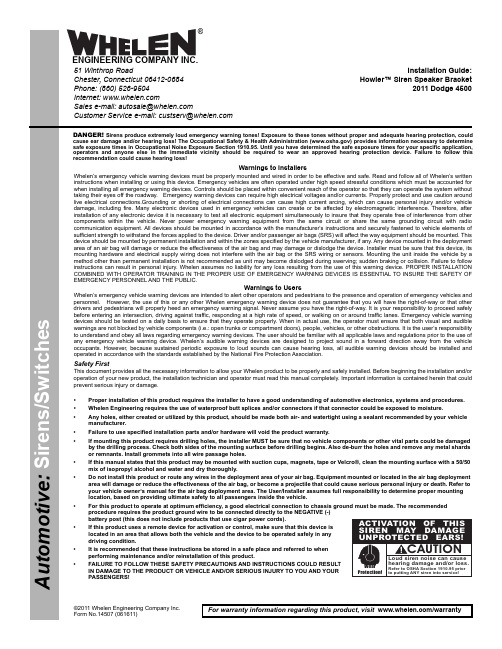
Page 1©2011 Whelen Engineering Company Inc.Form No.14507 (061611)A u t o m o t i v e : S i r e n s /S w i t c h e sFor warranty information regarding this product, visit /warrantyDANGER! Sirens produce extremely loud emergency warning tones! Exposure to these tones without proper and adequate hearing protection, could cause ear damage and/or hearing loss! The Occupational Safety & Health Administration () provides information necessary to determine safe exposure times in Occupational Noise Exposure Section 1910.95. Until you have determined the safe exposure times for your specific application,operators and anyone else in the immediate vicinity should be required to wear an approved hearing protection device. Failure to follow this recommendation could cause hearing loss!•Proper installation of this product requires the installer to have a good understanding of automotive electronics, systems and procedures.•Whelen Engineering requires the use of waterproof butt splices and/or connectors if that connector could be exposed to moisture.•Any holes, either created or utilized by this product, should be made both air- and watertight using a sealant recommended by your vehicle manufacturer.•Failure to use specified installation parts and/or hardware will void the product warranty.•If mounting this product requires drilling holes, the installer MUST be sure that no vehicle components or other vital parts could be damaged by the drilling process. Check both sides of the mounting surface before drilling begins. Also de-burr the holes and remove any metal shards or remnants. Install grommets into all wire passage holes.•If this manual states that this product may be mounted with suction cups, magnets, tape or Velcro®, clean the mounting surface with a 50/50 mix of isopropyl alcohol and water and dry thoroughly.•Do not install this product or route any wires in the deployment area of your air bag. Equipment mounted or located in the air bag deployment area will damage or reduce the effectiveness of the air bag, or become a projectile that could cause serious personal injury or death. Refer to your vehicle owner’s manual for the air bag deployment area. The User/Installer assumes full responsibility to determine proper mounting location, based on providing ultimate safety to all passengers inside the vehicle.•For this product to operate at optimum efficiency, a good electrical connection to chassis ground must be made. The recommended procedure requires the product ground wire to be connected directly to the NEGATIVE (-) battery post (this does not include products that use cigar power cords).•If this product uses a remote device for activation or control, make sure that this device is located in an area that allows both the vehicle and the device to be operated safely in any driving condition.•It is recommended that these instructions be stored in a safe place and referred to when performing maintenance and/or reinstallation of this product.•FAILURE TO FOLLOW THESE SAFETY PRECAUTIONS AND INSTRUCTIONS COULD RESULT IN DAMAGE TO THE PRODUCT OR VEHICLE AND/OR SERIOUS INJURY TO YOU AND YOUR PASSENGERS!CAUTIONLoud siren noise can cause hearing damage and/or loss.Refer to OSHA Section 1910.95prior to putting ANY siren into service!Wear Protection!ACTIVATION OF THIS SIREN MAY DAMAGE UNPROTECTED EARS!Warnings to InstallersWhelen’s emergency vehicle warning devices must be properly mounted and wired in order to be effective and safe. Read and follow all of Whelen’s written instructions when installing or using this device. Emergency vehicles are often operated under high speed stressful conditions which must be accounted for when installing all emergency warning devices. Controls should be placed within convenient reach of the operator so that they can operate the system without taking their eyes off the roadway. Emergency warning devices can require high electrical voltages and/or currents. Properly protect and use caution around live electrical connections.Grounding or shorting of electrical connections can cause high current arcing, which can cause personal injury and/or vehicle damage, including fire. Many electronic devices used in emergency vehicles can create or be affected by electromagnetic interference. Therefore, after installation of any electronic device it is necessary to test all electronic equipment simultaneously to insure that they operate free of interference from other components within the vehicle. Never power emergency warning equipment from the same circuit or share the same grounding circuit with radio communication equipment. All devices should be mounted in accordance with the manufacturer’s instructions and securely fastened to vehicle elements of sufficient strength to withstand the forces applied to the device. Driver and/or passenger air bags (SRS) will affect the way equipment should be mounted. This device should be mounted by permanent installation and within the zones specified by the vehicle manufacturer, if any. Any device mounted in the deployment area of an air bag will damage or reduce the effectiveness of the air bag and may damage or dislodge the device. Installer must be sure that this device, its mounting hardware and electrical supply wiring does not interfere with the air bag or the SRS wiring or sensors. Mounting the unit inside the vehicle by a method other than permanent installation is not recommended as unit may become dislodged during swerving; sudden braking or collision. Failure to follow instructions can result in personal injury. Whelen assumes no liability for any loss resulting from the use of this warning device. PROPER INSTALLATION COMBINED WITH OPERATOR TRAINING IN THE PROPER USE OF EMERGENCY WARNING DEVICES IS ESSENTIAL TO INSURE THE SAFETY OF EMERGENCY PERSONNEL AND THE PUBLIC.Warnings to UsersWhelen’s emergency vehicle warning devices are intended to alert other operators and pedestrians to the presence and operation of emergency vehicles and personnel. However, the use of this or any other Whelen emergency warning device does not guarantee that you will have the right-of-way or that other drivers and pedestrians will properly heed an emergency warning signal. Never assume you have the right-of-way. It is your responsibility to proceed safely before entering an intersection, driving against traffic, responding at a high rate of speed, or walking on or around traffic lanes. Emergency vehicle warning devices should be tested on a daily basis to ensure that they operate properly. When in actual use, the operator must ensure that both visual and audible warnings are not blocked by vehicle components (i.e.: open trunks or compartment doors), people, vehicles, or other obstructions. It is the user’s responsibility to understand and obey all laws regarding emergency warning devices. The user should be familiar with all applicable laws and regulations prior to the use of any emergency vehicle warning device. Whelen’s audible warning devices are designed to project sound in a forward direction away from the vehicle occupants. However, because sustained periodic exposure to loud sounds can cause hearing loss, all audible warning devices should be installed and operated in accordance with the standards established by the National Fire Protection Association.Safety FirstThis document provides all the necessary information to allow your Whelen product to be properly and safely installed. Before beginning the installation and/or operation of your new product, the installation technician and operator must read this manual completely. Important information is contained herein that could prevent serious injury or damage.Installation Guide:Howler™ Siren Speaker Bracket2011 Dodge 450051 Winthrop RoadChester, Connecticut 06412-0684Phone: (860) 526-9504Internet: Sales e-mail: autosale@Customer Service e-mail: custserv@®ENGINEERING COMPANY INC.Page 25/16-18X 1-1/4BOLT(QTY 2)STRAP (QTY 2)5/16FLAT WASHER (QTY2)5/16-18ELASTIC STOP NUT (QTY 2)CLAMP MOUNTFig 1ABOTTOM OF SPEAKER5/16-18X 1-3/4BOLT (QTY 1)5/16FLAT WASHER (QTY1)SPACER (QTY 1)5/16-18ELASTIC STOP NUT (QTY 1)STRAP (QTY 2)TOP OF SPEAKERFig 1BCHANNELVENT HOLES MUST FACE BOTTOMSTRAPSlide speaker forward with strap located to rear of channel.Securing the siren speaker to the bracket:Main Bracket:Secure the clamp mount that you secured to the siren speaker in step 1, to the main bracket as shown in figure 2.Support Bracket:Extend the WHITE (positive) and BLACK (negative) speaker wires to your siren amplifier and refer to the amplifiers instructions for connections.IMPORTANT! READ THESE WARNINGS BEFORE CONTINUING!The Howler™ Supplemental Siren was designed for use in high-risk areas such as an intersection. It is not intended to be, nor should be operated as a replacement or alternative to the vehicle’s primary siren.The low-frequency tones of the Howler™ demonstrate significantly different audio characteristics as compared to those of a traditional higher-frequency siren. While the low-frequency tones are better able to penetrate other vehicles, thus alerting drivers to the presence of the responding emergency vehicle, these tones may also penetrate into the responding vehicle itself. This could potentially expose the operator to increased noise levels.To help eliminate overexposure, the Howler™ siren has been designed with a built-in timing circuit. The Occupational Safety & Health Administration (OSHA) () provides information necessary to determine safe exposure times in Noise and Hearing Conservation, Section 1910.95(Occupational Noise Exposure). Until you have determined the safe exposure times for your specific application, this siren should be configured for the minimum operating time and operators should be required to use an approved hearing protection device. FAILURE TO FOLLOW THIS RECOMMENDATION COULD CAUSE HEARING LOSS!。
EDMI EM 710-MK2多脉冲多角度回声声音器产品说明书

Multibeam echo sounderHigh resolution seabed mapping systemSystem overviewThe EM 710-MK2 multibeamecho sounder is a high to very high resolution seabed mapping system capable of meeting all relevant survey standards. The coveragefor EM 710-MK2 is increased by replacing the receiver interface boards with new boards and new transceiver SW. The transducer arrays are the same. The system configuration can be tailored to the user requirements, allowing for choice of beam widths as well as transmission modes.The minimum acquisition depth is from less than 3 m below its transducers, and the maximum acquisition depth is approximately 2800 m, dependant upon array size. Across track coverage (swath width) is up to 5.5 times water depth, to a maximum of more than 3000 m.Echo sounder models There are three basic versions of the EM 710-MK2 system, with different range performances:• EM 710‑MK2 ‑ Full performance version.• EM 710S‑MK2 ‑ CW pulse forms only.• EM 710RD‑MK2 ‑ Short CW pulse only.Choice of beamwidthsThe along track beamwidth depends upon the chosen transmit transducer configuration with 0.5,1 and 2º available as standard. The receive beam width is either 1 or2º depending on the chosen receive transducer.Innovative acoustic principlesThe EM 710-MK2 operates at sonar frequencies in the 65 to 100 kHz range in shallow waters, and can use frequencies down to 40 kHz to extend coverage in deep waters. The transmit fan is divided into three sectors to maximize range capability, but also to suppress interference from multiples of strong bottom echoes.The sectors are transmittedsequentially within each ping,and uses distinct frequencies orwaveforms.EM 710S‑MK2 and EM 710RD‑MK2both use CW pulses of differentlengths. The full performance version,EM 710-MK2, supports even longer,compressible waveforms (FM sweep).Fully stabilized andfocused beamsThe system applies beam focusingto both transmit and receive beamsin order to obtain the maximumresolution also inside the acousticnear‑field.During transmission, focusing isapplied individually to each transmitsector with a focus point on the rangedefined by the previous ping, to retainthe angular resolution in the nearfield. Dynamic focusing is appliedto all receive beams. The transmitbeams are electronically stabilizedfor roll, pitch and yaw, while thereceive beams are stabilized for rollmovements.Controlled, dense andaccurate soundingsThe beam spacing may be set to beeither equiangular or equidistant.The maximum swath coverage may belimited by the operator either in angleor in swath width without reducingthe number of beams. A combinationof phase and amplitude bottomdetection algorithm is used, in orderto provide soundings with the bestpossible accuracy.The number of beams varies with thebeamwidth. The system generates400 soundings per swath for 1º RX,and 200 soundings for a 2º RXsystem. (800 and 400 in dual swathmode)TransducersThe active elements of theEM 710-MK2 transducers are basedupon composite ceramics, a designwhich has several advantages, inparticular increased bandwidth andtighter performance tolerances.The 1x2º and 2x2º versions canbe mounted on a pole for portabledeployment.For larger transducer versions arepermanent mounting like; flush withthe hull, in a blister or in a gondolaconstruction a possible solution.EM 710-MK2 can also be deliveredwith ice-reinforced transducer anda strengthen mounting frame forinstallation on icebreakers.Transceiver UnitThe EM 710-MK2 electronicssystem is a true wideband design.The transmitter circuits are fullyprogrammable to support anyfrequency or pulse form. The use ofFM sweep as a pulse form allowsfor more energy per pulse and thusincreased range performance, withoutany sacrifice of range resolution. Thenon-saturating and low noise receiversand A/D converters are of floatingpoint type, resulting in a dynamicrange of more than 140 dB. Theconventional TVG compensation isno longer needed. Filters, correlatorsand beamformers are fully digitalimplementations, and the beamforming method is by time delays, toallow for the wide frequency band ofthe system.The 2 x 2º RD version is deliveredwith a shorter (portable) transceivercabinet.Operator StationThe Operator Station is the HWS highperformance PC workstation usingWindows ®. The HWS is normallysupplied with a 24” industrializedLCD monitor. Support for a secondmonitor is included. A spillproofUS keyboard and a standard opticalmouse is normally supplied.Advanced functions• Integrated seabed acoustical imaging capability is included as standard. Software to use this data for automatic seabed classification is available from many third‑party suppliers.• A real time display window for water column backscatter is available. Logging of water column data and of raw stave data (before beamforming) is a system option.• A high density beam processing mode provides up to 400 or 200 soundings per swath. In order to make the soundings independent, a limited range window is set inside each beam for each sounding. In practice this is equivalent to synthetically sharpening the beam width. (Down to 25% in the outer beams)• The system generates two separate alongtrack swaths per ping. With dual swath the system can produce up to 800 ping.soundingsper• The Operator Station includes the necessary operator controls for setting up and running the system, data logging and system testing.• The Seafloor Information System (SIS) includes an extensive set of graphical displays for data quality control, as well as system calibration and other tools which are required. SIS supports on-line real-time data cleaning to improve the overall survey efficiency.• Post-processing software for the EM 710-MK2 is available from many third-party suppliers.390849 / Rev.C / November 2014Strandpromenaden 50P.O.Box 111N-3191Horten,NorwayKongsberg Maritime ASTelephone:+4733023800Telefax:+4733044753******************** Frequency range 40 to 100 kHz Max ping rate 30 HzSwath coverage sector Up to 140 degrees Min depth3 m below transducerRoll stabilized beams Yes, ±15°Pitch stabilized beams Yes, ±10°Yaw stabilized beams Yes, ±10°Sounding patternsEquiangular Equidistant High DensityMax depth (approximate values)0.5 x 1°EM710-MK2EM710S -MK2EM710RD -MK22800 m 1750 m 600 m CW transmit pulses 0.2 to 2 ms 0.2 to 2 ms 0.2 ms FM sweep pulseMax. 120 msNoNoTransducer choices 0.5 x 1°1 x 1°1 x 2°2 x 2°Availability Not EM 710RD‑MK2Not EM 710RD‑MK2All models All models TX dimensions (L x W x H)1940 x 224 x 118 mm 970 x 224 x 118 mm 970 x 224 x 118 mm 490 x 224 x 118 mm RX dimensions (L x W x H)970 x 224 x 118 mm 970 x 224 x 118 mm 490 x 224 x 118 mm 490 x 224 x 118 mm Max no. of soundings per ping (Dual swath mode)800800400400Kongsberg Maritime is engaged in continuous development of its products, and reserves the right to alter the specifications without further notice.Transceiver Unit dimensions (W x H x D)540 x 841 x 750 mm (including shockabsorbers)540 x 573 x 750 mm ‑ Standard for EM710RD‑MK2 2 x 2° version (Bulkhead mounting)EM ® is a registered trademark of Kongsberg Maritime AS in Norway and other countries.0.5 x 1°1 x 1° 1 x 2°2 x 2°Max coverage winter*2650250023502100Max coverage summer*3050285026502450Max depth winter*2650250023502200Max depthsummer*2800270025502400* Estimated depth and coverage for EM 710-MK2, based on BS= -20dB, NL= 45 dB, f = 40 kHz。
Ocean Way Audio Pro2A专业音响系统操作手册说明书

Manual of Operations Ocean Way Audio – Pro2A Professional Sound SystemContents1)Pro2A Description2)Safety Instructions and Warnings! (please read carefully)3)Inputs and Controls4)Input selectors & Legends5)S10A & S12A Sub-Bass options6)Specifications7)Warranty8)Maintenance1)Pro2APro2A is the latest addition to the OWA speaker line achieving efficient distortion-free dynamic range in an aesthetically appealing trapezoidal profile. Its cabinet features a sleek design with attention to time alignment, reduce baffle reflections and materials designed to minimize low frequency resonance. Its port is optimized to increase the woofer's low frequency extension and sound pressure level capacity.Pro2A’s HF driver is a high definition silk fabric dome design with excellent mechanical linearity. The LF driver is geometrically reinforced aluminum cone with a vented cast aluminum chassis yielding optimum strength and “high-power linearity”. Combined with the cabinet, the system offers minimal reflection, high resolution and low listening fatigue over the entire audio spectrum.Our two-way, self-powered design delivers outstanding performance allowing for flexibility of placement in the room with a uniform frequency response of 35Hz to 25kHz, and 110 dB maximum SPL between channels. Its overload protection circuitry ensure that drivers and amplifiers are protected, providing long term system reliability. The speaker allows the professional to hear great detail with a natural, open and accurately image. The Pro2A stands well above competitive monitor speakers in its price range.2) Safety Instructions and WarningsRead the information for usePlease keep this user manual in a safe place during the lifetime of the product.Heed all warnings.Follow all instructions.Do not use this product near water (for example, in damp rooms or near a swimming pool).Clean only with dry cloth.Do not cover the heat sink. Install in accordance with the user manual.Do not install near any heat sources such as radiators, heat registers, stoves, or other apparatus that produce heat.Protect the power cord from being walked on, pinched or damaged in any other way. Pay particular attention to plugs and the point where they exit from the Amplifier Unit.The Amplifier Unit can only be disconnected from the power supply by removing the plug, which must be freely accessible at all times. Unplug this Amplifier Unit during lightning storms or when unused for long periods of time.Refer all servicing to qualified service personnel.ServicingDo not attempt to service this product yourself. As opening or removing covers may expose you to dangerous voltage or other hazards, the amplifier may only be opened by qualified personnel. Pleaserefer to your dealer/distributor.Servicing and Replacement PartsAll service and repair work must be carried out by an authorized dealer/distributor. When replacement parts are required, please ensure that the dealer/distributor only uses replacement parts specified by the manufacturer. The use of unauthorized replacement parts may result in injury and/or damage through fire or electric shock or other electricity -related hazards.Ventilation and heat sinkThe heat sink is provided to ensure reliable operation of the Amplifier Unit and to protect it from overheating. The heat sink must not be blocked or covered. This product should not be installed unless proper ventilation is provided or manufacturer’s instructions have been adhered to.Water and MoistureDo not use this product near water (for example, in damp rooms or near a swimming pool).CleaningUnplug the Amplifier Unit from the wall outlet before cleaning. Do not use liquid or aerosol cleaners.Power -Cord ProtectionPower supply cords should be routed so that they are not likely to be walked on or pinched by items placed upon them or against them, paying particular attention to cords and plugs, and the point where they exit from the Amplifier Unit.LightningFor added protection of the product during lightning storms, or when it is left unattended and unused for long periods of time, unplug it from the wall outlet. This will prevent damage to the product due to lightning and power-line surges. Disconnection from the mains power supply can only be achieved by removing the plug from the mains socket and by external disconnection of all poles from the mains. AccessoriesDo not place this product on an unstable cart, stand, tripod, bracket, or table. The product may fall, causing serious injury, and serious damage to the product.ConnectingWhen you connect this speaker to other equipment, turn off the power and unplug all of the equipment from the supply source. Failure to do so may cause an electric shock and serious personal injury. Read the user's manual of the other equipment carefully and follow the instructions when making the connections.Sound VolumeReduce the system volume to minimum before you turn on the amplifier to prevent sudden high levels of sound which may cause hearing or speaker damage.Precautions when connecting to MAINS INWhen mounting or connecting the product always disconnect it from mains. Only connect the product to an appropriate AC circuit and outlet, according to the requirements indicated on the rating plate. If a power cut occurs while the amplifier is switched on, it will restart automatically once the power supply has been restored. All settings prior to the loss of power will be maintained. IMPORTANT: Always connect the Product to mains through the MAINS IN connector on the Amplifier Unit.DO NOT REMOVE MAINS CONNECTOR GROUND, IT IS ILLEGAL ANDDANGEROUS.AC power 115/230v switchMake sure to correctly configure with the correct voltage for your country.3) Inputs and Controls Pro2A Master VolumeThe Master Volume allows trimming the speaker input gain when desired.4) Input Selection and LegendsPro2ALED 1–when illuminated indicates preset selected requires an analog signalLED2– when illuminated indicates preset selected requires an AES-EBU digital signalLEDS 3 & 4 - will be illuminated or dark in combinations specified in the legend aboveTo indicate which of the 4 presets is currently active.Preset 1– default preset the speaker is shipped with. It is an analog input 2-way (full range)configuration. Use Analog In XLR. (LED 1 on, LED 3 & 4 off).Preset 2- Is an analog 3-way (85Hz 4th order L-R high pass filter) for use with a sub-woofer.Use Analog In XLR (LED 1 on, LED 3 off / LED 4 on).Preset 3– Is an AES-EBU digital left input with 2-way response. Use Digital In XLR (LED 2 on, LED 3 on / LED 4 off). Preset 4– Is an AES-EBU digital right input with 2-way response. Use Digital In XLRSelecting Digital or Analog InputsUsing a small diameter blunt tool (i.e. plain end of a cotton swab), depress the LED Selector pushbutton for a short (1/2 second or less) duration. Each press will toggle the LEDS into different flashing sequences that will match the legend above. When the desired sequence is flashing, depress the switch for a full second. This will load that program and the LEDs will change from flashing to full illumination. N.B. A long push (1 sec or more) without first being preceded by a short push will toggle the input from its alternate state (analog to digital or visa-versa).You’ll see LED 1 or LED 2 change to their opposite state to indicate this. Avoid doing this unintentionally. Begin with short pushes to toggle through the 4 preset options and use the long push to select the desired preset.Signal Flow 2-Way & 3-WayThe Pro2A is configured as a 2-way system with no programmed roll-off in the low end response. There is a factory preset installed that will allow the speaker’s low frequency response to be extended by adding a sub-bass cabinet. Ocean Way Audio offers the S10A and the S12A subwoofer which has been added to create a balanced system response.Select Preset 2 - (LED 1 on, LED 3 off / LED 4 on).5) S10A & S12A Description The Power Switch (toggle) has three positions.1.) In the left most position the unit is powered OFF.2.) In the center position the unit is in Auto mode. It can be powered on uniting the 12V trigger inputs orby feeding audio into the input XLR. In the absence of either it will enter STANDBY mode with the red LED illuminating.When the trigger is activated or audio is supplied it will power up and the green LED will illuminate.3.) The right most position is will power up to ON with the green LED illuminating. It will remain ON in this position.The Voltage auto selects between 100v and 240v-115W 50/60HZS10A & S12A Description GAIN is the volume control. A suggested starting position is 12 o’clock when matched with HR5 speakers. Adjust upor down to suit positioning in your room. (Closer to a wall or a corner on the floor will increase the low frequency response.LF Adjust incorporated a LF shelf @ 45 Hz +/- 5 db in 1 db incrementsCrossover switch selects frequencies from 60 / 65 / 70 / 75 / 80 /85 / 90 /95 / 100 / 110 / 120hzDelay adjusts from 0 to 20 ms.12V trigger (AC or DC) will turn the unit on and off when power switch is in center (Auto) position. The jacks are paralleled to daisy chain to other auto powered products. With switch in center position and no trigger utilized, the unit will power ON when audio is sent to the input XLRs.Balanced XLR IN & OUT jacks are paralleled and a direct feed through. Signal does not go through any electronics.6) SpecificationsTech Specs Pro2APowered YES, Accepts analog/digital inputs 24 bit / 192 kHz Driver Configuration2-wayHF Driver Size1"LF Driver Size8"LF Driver Power Amp125wattsHF Driver Power Amp125wattsAES3 Digital Inputs YesFrequency Range35Hz > 25 kHzMaximum Peak SPL110dbEnclosure Type portedHeight16"Width11.5"Depth13.5"Weight45 lbs7) WarrantyOcean Way Audio speakers are under limited warranty as described in the following conditions.1.Warranty period starts as of date of purchase from the authorized dealer.2.OWA reserves the right to request original purchase receipt as proof of the date of purchase.3.Electronic components and cabinetry are warranted for a period of two (2) years against manufacturing defect, coveringparts and labor for necessary repairs.4.Speaker driver components are warranted for a period of one (1) year against manufacturing defect.5.The manufacturer’s warranties are limited to physical defects in the materials, parts and workmanship used in making theproduct.6.Misuse, incorrect installation, handling, repairs or modifications performed by unauthorized persons, abnormal conditions,damage due to accidents such as power surges, water, fire, or any other are excluded from any warranty claims.7.OWA warrants all service repairs and replacements for 180 days from the date of return to the customer/owner.Technical Support and ServiceFor warranty service and assistance, contact the original authorized dealer/distributor to arrange for return and/ or repair of the product. OWA will strive to satisfy all service requests in the fastest manner possible. Under the warranty, OWA will repair, or atits discretion, replace the product at no charge, provided it is returned (postage paid) to an authorized OWA service center. Any shipping or duties incurred are the customer’s responsibility. Products should be returned suitably packaged to protect from shipping damage, or in their original packaging. OWA shall be the sole and final authority to determine the validity of all warranty issues. All non-warranty repairs for current products will be charged according to the service repair pricing schedule. Repair prices will either be based on a flat fee for repair or replacement, or will be estimated depending on the repair deemed necessary.8)MaintenanceExterior surfaces of this product may be cleaned using a non-abrasive lint-free cloth lightly damped with water. Disconnect the mains power cable when cleaning to avoid risk of electric shock.Do not use alcohol or ammonia based cleaners.Driver active surfaces will not require cleaning as they are deep-set inside horn expansionsOcean Way AudioHistoryAbout Ocean WayIt all started with speakers. Ocean Way Recording began in 1968, as a showcase for Allen’s custom monitors.Allen needed impressive sounding material for his speakers so he began to record music that sounded dramatic! The studio business boomed and he met the demand with many rooms in several locations. At the peak of the studio business, Allen designed and owned four recording studio complexes.Five time Grammy® Award winning Allen Sides has personally recorded over 1,000 albums, many of which have become audiophile classics. He has worked with the finest and most famous artists of the last four decades. Albums recorded in Allen’s studios have sold over a billion copies. Allen’s hearing capabilities enables our engineers to translate every sonic nuance, bringing a new dimension and understanding to what is possible in high-end speaker design. His ears are our final design tool.Ocean Way Hollywood Ocean Way Nashville Ocean Way Record One Ocean Way St. Barts Through-out the history of Ocean Way Studios, we built the monitor systems for all the control roomsand private studios for selected elite cliental.These many accomplishments, paved the way forOcean Way AudioThe HR Series delivers “the” sound of Ocean Way Studios in a free standing design. Engineering speaker systems for professionals; incorporating over 45 years of award winning experience。
声音导引系统(2)

声音导引系统(2)
孙南生;徐吉鑫;钟伯辉
【期刊名称】《电子制作》
【年(卷),期】2010(003)003
【摘要】@@ 一、方案简介rn本系统是一个利用单片机技术实现的智能声音导引系统.系统包括两个部分:移动声源系统和声源坐标采集系统.
【总页数】4页(P42-45)
【作者】孙南生;徐吉鑫;钟伯辉
【作者单位】深圳职业技术学院
【正文语种】中文
【相关文献】
1.声音导引系统中位置控制算法的研究 [J], 姜宏伟;徐其迎;陈旭
2.声音导引智能系统 [J], 蔡卫刚
3.声音导引电动车系统硬件设计 [J], 王昊鹏;刘泽乾
4.基于单片机的声音导引自动定位系统设计 [J], 艾青楠;金成宰;宋海波
5.基于飞思卡尔单片机的声音导引系统设计 [J], 张茂云;陈风龙;唐晨
因版权原因,仅展示原文概要,查看原文内容请购买。
- 1、下载文档前请自行甄别文档内容的完整性,平台不提供额外的编辑、内容补充、找答案等附加服务。
- 2、"仅部分预览"的文档,不可在线预览部分如存在完整性等问题,可反馈申请退款(可完整预览的文档不适用该条件!)。
- 3、如文档侵犯您的权益,请联系客服反馈,我们会尽快为您处理(人工客服工作时间:9:00-18:30)。
甘肃省大学生电子设计大赛设计报告
题目:声音导引系统
院校:甘肃省河西学院
参赛学生姓名:吉彦平尹喜金梅艳
指导教师:顾建雄南雅公黄小娜
摘要:本文对声音引导系统的整体设计方案进行了全面的分析,主要分为四个部分:声源设计、声音发射、声音信号接受和指令信号的产生与发射,以及ASSP芯片(型号MMC-1)控制声源运动。
设计作品基本满足各项技术指标。
关键词:无线信号传输红外传感器ASSP芯片(MMC-1)
1 系统方案
1.1设计要求
1.1.1 基本要求
(1)制作可移动的声源。
可移动声源产生的信号为周期性音频脉冲信号,如图1所示,声音信号频率不限,脉冲周期不限。
(2)可移动声源发出声音后开始运动,到达Ox 线并停止,这段运动时间为响应时间,测量响应时间,用下列公式计算出响应的平均速度,要求平均速度大于 5cm/s 。
(3)可移动声源停止后的位置与Ox 线之间的距离为定位误差,定位误差小于3cm 。
(4)可移动声源在运动过程中任意时刻超过Ox 线左侧的距离小于5cm 。
(5)可移动声源到达Ox 线后,必须有明显的光和声指示。
(6)功耗低,性价比高。
1.1.2 发挥部分
(1)将可移动声源转向180度(可手动调整发声器件方向),能够重复基本要求。
(2)平均速度大于10cm/s 。
(3)定位误差小于1cm 。
(4)可移动声源在运动过程中任意时刻超过Ox 线左侧距离小于2cm 。
(5)在完成基本要求部分移动到Ox 线上后,可移动声源在原地停止5s ~10s ,然后利用接收器A 和C ,使可移动声源运动到W 点,到达W 点以后,必须有明显的光和声指示并停止,此时声源距离W 的直线距离小于1cm 。
整个运动过程的平均速度大于10cm/s 。
图1 信号波形示意图
可移动声源的起始位置到Ox 线的垂直距离 响应时间
平均速度=
1.2 系统方案比较
1.2.1声源设计
方案一:利用单片机产生音频脉冲信号,并经过功放,推动扬声器发声。
1.2.2声音发射
方案一:如图2所示,采用LM386对输入音频信号进行放大。
如1脚和8脚悬空,电压增益为20,则使用的元件最少。
如在1脚和8脚之间增加一只外接电阻和电容,便可将电压增益调为20-200间之任意值。
该芯片的优点是电压增益可调;外围元件少,一定程度上减少了杂散电容、电阻等元器件上的无谓损耗,且电路比较简单,成本低;低失真度,有利于音频信号的传输;静态功耗低,约为4mA,可用于电池供电。
其缺点是输出端电容耦合虽有益音频信号输出,但也在一定程度上对静态直流电流的隔断也会不利于维持预定的增益。
图2音频功率放大电路(放大增益=200)
方案二:
1.2.3声音接受
方案一:采用如图3声控电路。
利用驻极体话筒,将声音的强弱转化为电信号,并经三极管共射级放大电路放大。
静态时,根据图中参数可知三极管工作在饱和区。
动态时,如果环境的声音信号很弱,三极管仍处于饱和状态,B 点为低电平。
当环境声音信号达到一定强度时,集电极B 点电位随着声音而高低变化,当声音达到一定强度时,B 点输出高电位。
将此高电位做为单片机的驱动脉冲,驱动单片机工作。
可移动声源在Ox 线上重新启动位置到移动停止点的直线距离
再次运动时间
平均速度=
图3声控电路
方案二:采用如图4所示的语音输入双差分放大电路。
信号首先经过差分放大,再经过第二级放大。
自动增益控制部分利用场效应管工作在可变电阻区,漏源电阻受栅源电压控制的特性,利用压控放大器,整流滤波电路,场效应管闭环来实现。
VAMPL = 1m
VOFF = 0
图4 双差分放大电路
方案三:采用含有两个与非门构成的延时控制电路。
当声音信号输入时,经过两级转换,实现后级所需的高电平,以保证延时顺利实现。
1.2.4红外传感
方案一:选用红外线光电开关。
运用对射形的方式,由投光器和受光器一对于一体,由物体是否遮断投光器和受光器的重合光轴来判断物体的有无。
此形检测距离最远,灵敏度高。
方案二:选用无线发射接收模块。
1.3系统基本方案
2. 系统的硬件与实现
2.1 主要单元电路的设计
3系统的软件设计。