数控铣床毕业设计外文翻译 2
数控车床毕业设计外文翻译
LathesLathes are machine tools designed primarily to do turning, facing and boring, Very little turning is done on other types of machine tools, and none can do it with equal facility. Because lathes also can do drilling and reaming, their versatility permits several operations to be done with a single setup of the work piece. Consequently, more lathes of various types are used in manufacturing than any other machine tool.The essential components of a lathe are the bed, headstock assembly, tailstock assembly, and the leads crew and feed rod.The bed is the backbone of a lathe. It usually is made of well normalized or aged gray or nodular cast iron and provides s heavy, rigid frame on which all the other basic components are mounted. Two sets of parallel, longitudinal ways, inner and outer, are contained on the bed, usually on the upper side. Some makers use an inverted V-shape for all four ways, whereas others utilize one inverted V and one flat way in one or both sets, They are precision-machined to assure accuracy of alignment. On most modern lathes the way are surface-hardened to resist wear and abrasion, but precaution should be taken in operating a lathe to assure that the ways are not damaged. Any inaccuracy in them usually means that the accuracy of the entire lathe is destroyed.The headstock is mounted in a foxed position on the inner ways, usually at the left end of the bed. It provides a powered means of rotating the word at various speeds . Essentially, it consists of a hollow spindle, mounted in accurate bearings, and a set of transmission gears-similar to a truck transmission—through which the spindle can be rotated at a number of speeds. Most lathes provide from 8 to 18 speeds, usually in a geometric ratio, and on modern lathes all the speeds can be obtained merely by moving from two to four levers. An increasing trend is to provide a continuously variable speed range through electrical or mechanical drives.Because the accuracy of a lathe is greatly dependent on the spindle, it is of heavy construction and mounted in heavy bearings, usually preloaded tapered roller or ball types. The spindle has a hole extending through its length, through which long bar stock can be fed. The size of maximum size of bar stock that can be machined when the material must be fed through spindle.The tailsticd assembly consists, essentially, of three parts. A lower casting fits on the inner ways of the bed and can slide longitudinally thereon, with a means for clamping the entire assembly in any desired location, An upper casting fits on the lower one and can be moved transversely upon it, on some type of keyed ways, to permit aligning the assembly isthe tailstock quill. This is a hollow steel cylinder, usually about 51 to 76mm(2to 3 inches) in diameter, that can be moved several inches longitudinally in and out of the upper casting by means of a hand wheel and screw.The size of a lathe is designated by two dimensions. The first is known as the swing. This is the maximum diameter of work that can be rotated on a lathe. It is approximately twice the distance between the line connecting the lathe centers and the nearest point on the ways, The second size dimension is the maximum distance between centers. The swing thus indicates the maximum work piece diameter that can be turned in the lathe, while the distance between centers indicates the maximum length of work piece that can be mounted between centers.Engine lathes are the type most frequently used in manufacturing. They are heavy-duty machine tools with all the components described previously and have power drive for all tool movements except on the compound rest. They commonly range in size from 305 to 610 mm(12 to 24 inches)swing and from 610 to 1219 mm(24 to 48 inches) center distances, but swings up to 1270 mm(50 inches) and center distances up to 3658mm(12 feet) are not uncommon. Most have chip pans and a built-in coolant circulating system. Smaller engine lathes-with swings usually not over 330 mm (13 inches ) –also are available in bench type, designed for the bed to be mounted on a bench on a bench or cabinet.Although engine lathes are versatile and very useful, because of the time required for changing and setting tools and for making measurements on the work piece, thy are not suitable for quantity production. Often the actual chip-production tine is less than 30% of the total cycle time. In addition, a skilled machinist is required for all the operations, and such persons are costly and often in short supply. However, much of the operator’s time is consumed by simple, repetitious adjustments and in watching chips being made. Consequently, to reduce or eliminate the amount of skilled labor that is required, turret lathes, screw machines, and other types of semiautomatic and automatic lathes have been highly developed and are widely used in manufacturing.2 Numerical ControlOne of the most fundamental concepts in the area of advanced manufacturing technologies is numerical control (NC). Prior to the advent of NC, all machine tools ere manually operated and controlled. Among the many limitations associated with manual control machine tools, perhaps none is more prominent than the limitation of operator skills. With manual control, the quality of the product is directly related to and limited to the skills of the operator. Numerical control represents the first major step away from human control of machine tools.Numerical control means the control of machine tools and other manufacturing systems through the use of prerecorded, written symbolic instructions. Rather than operating a machine tool, an NC technician writes a program that issues operational instructions to the machine tool. For a machine tool to be numerically controlled, it must be interfaced with a device for accepting and decoding the programmed instructions, known as a reader.Numerical control was developed to overcome the limitation of human operators, and it has done so. Numerical control machines are more accurate than manually operated machines, they can produce parts more uniformly, they are faster, and the long-run tooling costs are lower. The development of NC led to the development of several other innovations in manufacturing technology:Electrical discharge machining,Laser cutting,Electron beam welding.Numerical control has also made machine tools more versatile than their manually operated predecessors. An NC machine tool can automatically produce a wide of parts, each involving an assortment of widely varied and complex machining processes. Numerical control has allowed manufacturers to undertake the production of products that would not have been feasible from an economic perspective using manually controlled machine tolls and processes.Like so many advanced technologies, NC was born in the laboratories of the Massachusetts Institute of Technology. The concept of NC was developed in the early 1950s with funding provided by the U.S. Air Force. In its earliest stages, NC machines were able to made straight cuts efficiently and effectively.However, curved paths were a problem because the machine tool had to be programmed to undertake a series of horizontal and vertical steps to produce a curve. The shorter the straight lines making up the steps, the smoother is the curve, Each line segment in the steps had to be calculated.This problem led to the development in 1959 of the Automatically Programmed Tools (APT) language. This is a special programming language for NC that uses statements similar to English language to define the part geometry, describe the cutting tool configuration, and specify the necessary motions. The development of the APT language was a major step forward in the fur ther development from those used today. The machines had hardwired logic circuits. The instructional programs were written on punched paper, which was later to be replaced by magnetic plastic tape. A tape reader was used to interpret the instructions written on the tape for the machine. Together, all of this represented a giant step forward in the control of machine tools. However, there were a number of problems with NC at this point in its development.A major problem was the fragility of the punched paper tape medium. It was common for the paper tape containing the programmed instructions to break or tear during a machining process. This problem was exacerbated by the fact that each successive time a part was produced on a machine tool, the paper tape carrying the programmed instructions had to be rerun through the reader. If it was necessary to produce 100 copies of a given part, it was also necessary to run the paper tape through the reader 100 separate tines. Fragile paper tapes simply could not withstand the rigors of a shop floor environment and this kind of repeated use.This led to the development of a special magnetic plastic tape. Whereas the paper carried the programmed instructions as a series of holes punched in the tape, the plastic tape carried the instructions as a series of magnetic dots. The plastic tape was much stronger than the paper tape, which solved the problem of frequent tearing and breakage. However, it still left two other problems.The most important of these was that it was difficult or impossible to change the instructions entered on the tape. To made even the most minor adjustments in a program of instructions, it was necessary to interrupt machining operations and make a new tape. It was also still necessary to run the tape through the reader as many times as there were parts to be produced. Fortunately, computer technology became a reality and soon solved the problems of NC associated with punched paper and plastic tape.The development of a concept known as direct numerical control (DNC) solved the paper and plastic tape problems associated with numerical control by simply eliminating tape as the medium for carrying the programmed instructions. In direct numerical control, machine tools are tied, via a data transmission link, to a host computer. Programs for operating the machine tools are stored in the host computer and fed to the machine tool an needed via the data transmission linkage. Direct numerical control represented a major step forward over punched tape and plastic tape. However, it is subject to the same limitations as all technologies that depend on a host computer. When the host computer goes down, the machine tools also experience downtime. This problem led to the development of computer numerical control.3 TurningThe engine lathe, one of the oldest metal removal machines, has a number of useful and highly desirable attributes. Today these lathes are used primarily in small shops where smaller quantities rather than large production runs are encountered.The engine lathe has been replaced in today’s production shops by a wide variety of automatic lathes such as automatic of single-point tooling for maximum metal removal, andthe use of form tools for finish on a par with the fastest processing equipment on the scene today.Tolerances for the engine lathe depend primarily on the skill of the operator. The design engineer must be careful in using tolerances of an experimental part that has been produced on the engine lathe by a skilled operator. In redesigning an experimental part for production, economical tolerances should be used.Turret Lathes Production machining equipment must be evaluated now, more than ever before, this criterion for establishing the production qualification of a specific method, the turret lathe merits a high rating.In designing for low quantities such as 100 or 200 parts, it is most economical to use the turret lathe. In achieving the optimum tolerances possible on the turrets lathe, the designer should strive for a minimum of operations.Automatic Screw Machines Generally, automatic screw machines fall into several categories; single-spindle automatics, multiple-spindle automatics and automatic chucking machines. Originally designed for rapid, automatic production of screws and similar threaded parts, the automatic screw machine has long since exceeded the confines of this narrow field, and today plays a vital role in the mass production of a variety of precision parts. Quantities play an important part in the economy of the parts machined on the automatic screw machine. Quantities less than on the automatic screw machine. The cost of the parts machined can be reduced if the minimum economical lot size is calculated and the proper machine is selected for these quantities.Automatic Tracer Lathes Since surface roughness depends greatly on material turned, tooling , and feeds and speeds employed, minimum tolerances that can be held on automatic tracer lathes are not necessarily the most economical tolerances.In some cases, tolerances of 0.05mm are held in continuous production using but one cut . groove width can be held to 0.125mm on some parts. Bores and single-point finishes can be held to 0.0125mm. On high-production runs where maximum output is desirable, a minimum tolerance of 0.125mm is economical on both diameter and length of turn.车床车床主要是为了进行车外圆、车端面和镗孔等项工作而设计的机床。
外文翻译Numerically Controlled (NC) Machines
本科生毕业设计(论文)外文翻译毕业设计(论文)题目:剪叉式物流液压升降台外文题目:Numerically Controlled (NC) Machines译文题目:数控机床学生姓名:张龙专业:机械设计制造及其自动化指导教师姓名:张凯评阅日期:正文内容小四号字,宋体,行距1.5倍行距。
Numerically Controlled (NC) MachinesWith automatics, programming is expensive and can be justified only for long production runs. However, with machines incorporating feedback control, programs can be provided in the form of punched tapes or punched cards, which are relatively inexpensive to produce compared with disc and drum cams. These machines are known as numerically controlled (NC) machines and can be used economically in small-batch production.As the name implies, numerical control involves control on the basis of numerical information that specifies the relative position of the tool and workpiece. From the block diagram for a machine-tool control system in Fig. 12 it can be seen that two essential elements are added to an otherwise standard machine.The first added element is a means of driving the machine table or toolholder by a servomotor, and hence the motion of the tool or workpiece depends on the signal passed to the servomotor. The second added element is a transducer that continuously monitors the position of the tool or workpiece. The signal from the transducer is compared with that obtained from the tape, and any difference (or error) is converted to analog form, amplified, and used to drive the servomotor until the tool or workpiece position agrees with the position specified by the information on the tape.Fig. 12: Feedback loop for one axis of a machine-tool control system There are two basic types of NC systems: the point-to-point, or positioning, system and the continuous-path, or contouring, system. The point-to-point system would be applied, for example, to a vertical-drilling machine. If control of the two horizontal-motion axes of the table supporting the workpiece is arranged, the machine can be programmed to locate and then drill a specified pattern of holes. In the point-to-point system the path of the tool relative to the workpiece between holes is not important, and only the coordinates of the end point of each motion of the table are specified. The continuous-path system would be applied, for example, to a vertical-milling machine that was required to end mill a complicated shape, such as cam or pocket in a workpiece. In the continuous-path system the position of the tool relative to the workpiece must be continuously controlled while workpieces are being machined.With continuous-path, or contouring, systems the position of the tool relative to the workpiece is specified by a series of coordinates, and the control system is designed to follow a path between these points by interpolation. Some machines follow a straight-line path (linear interpolation); others follow a curved path (circular or parabolic interpolation).Numerical control can be applied to motions along or about any axis,·but two or three-axis control systems are the most common. In general, vertical-milling machines and lathes utilize continuous-path, or contouring control. Vertical-drilling machines jig borers, and small milling machines often use positional control.One sophisticated form of NC machine is known as the machining center. This machine is generally a vertical-milling machine with several axes of control and with automatic tool-changing facilities. The tools are usually held in a rotary magazine, and tool changes are commanded by the punched tape. Thus, with a machining center a complicated workpiece can be completely machined on all faces except the base through a combination of milling, drilling, boring, facing, reaming, and tapping operations. This type of system is therefore most suitable for the batch production of main components.A further refinement of numerical control is adaptive control. This type of system can adapt itself to the prevailing circumstances. These circumstances are measured by the system itself and might include the power required for the machining operation, the wear of the cutting tool or grinding wheel, the forces generated, or the onset of chatter or instability. The system ideally would be designed for automatic adjustment of the feed, speed, or tool position to produce components at minimum cost and within the tolerance specified. Such a system would be very expensive and has not yet found wide application.A relatively simple adaptive control system would automatically vary the cutting speed and feed in such a way as to maximize metal-removal rates without exceeding predetermined cutting forces and power consumption. Systems of this type are relatively inexpensive and can machine under near-optimum conditions.数控机床伴随着自动化产生,只有在长期的生产运行中,编程的价格很昂贵,同时又是合理的。
外文翻译

本科生毕业设计(论文)外文翻译毕业设计(论文)题目:JSC-013型数控卧式镗铣床刀库设计外文题目:Wide Trough Column Cam Numerical ControlProcessing Research译文题目:宽槽圆柱凸轮数控加工技术的研究学生姓名:武晓波专业:机自0705班指导教师姓名:李延斌评阅日期:英文原文Wide Trough Column Cam Numerical ControlProcessing ResearchSummary: Some questions produces which in view of the traditional milling method processing column cam, proposed one kind in view of the trough spaciously in the cutting tool diameter column cam path numerical control milling processing method. Through the analysis research, has established one kind of correct coordinates transformation model, and processes according to this conforms to the request wide trough column cam.Keywords: Numerical control processing Coordinates Transformation width trough column camMain TextThe column cam path is generally surrounds according to the certain rule in the round cylinder and so on the wide trough. Must satisfy below to the column cam path numerical control milling processing requests: 1.The column cam path working surface namely two sides plane of normal section lines must be strict parallel; 2.The column cam path must wait for the width in the work section. This is guarantees the roller in the column cam path the steady motion essential condition. When column cam path width not big, may find the corresponding diameter the end mill to carry on the processing along the trough cavity middle line, compared with is easy to process conforms to the above request column cam path. According to the existence information introduced that, at present the column cam milling processing all is realizes with this means. Because this method has too many limitations, brings many difficulties for the actual milling processing. For example when cannot find with the trough width size equal standard cutting tool, must carry on to the cutting tool changes the system.Regarding the trough width size big column cam path, is very difficult to find the diameter and the trough width equal standard cutting tool. Even if has the corresponding cutting tool, but also must consider the engine bed main axle output and the main axle and the work clothes jig rigidity limit, specially engine bed mainaxle structure to cutting tool limit. For example the numerical control engine bed host axle neck is 7: 24 40 inner cones, uses for parts JT40 the tool system, then most greatly only can use φ20mm end mill (no matter straight handle bit holder). This regarding the trough width is the 38mm column cam (is processing cam which this article narrates) said is unable to process, must seek the new processing method.Under and analyzes the research according to the experience, introduced one kind is smaller than the cam path width end mill with the diameter to carry on the numerical control processing to the column cam path the method, calls it the width trough column cam numerical control processing.First, Processing craftThe column cam path is surrounds in the round cylinder and so on the width trough, when its processing often is bigger than 360°. along the circumference surface milling scopeIs suitable for with to have the numerical control rotary abutment the vertical numerical control milling machine to carry on the processing. According to the column cam actual structure, selects the belt key the spindle makes when the cam processing the radial direction and the week to the localization datum, makes the axial localization datum by the spindle ledge, and the nose thread contracts the column cam with the spindle in front of through the nut. The column cam axial and the radial direction size is generally big, in order to overcome because the bracket processes time the cutting force creates in the spindle distortion and the processing process produces inspires trembles, uses a supporting on the tailstock, withstands the spindle center bore with the numerical control turnplate rotation spool thread coaxial apex to make the auxiliary supporting.The column cam path base on each section usually is and so on deep, selects the flat base column end mill processing generally. Before the column cam milling processing usually is a solid circular cylinder, must pass through working procedure and so on slot, rough machining, half precision work, precision work; Because the trough cavity width is big, Therefore, except the trough working procedure and a rough machining working procedure part of knives positions path may along beside the trough cavity middle line production, other knife position paths then must bealong the trough cavity center alignment left, are right nearby two according to theCorresponding .Figure 1 column cam path two-dimensional developed viewSecond, Solution modelIn the column cam path numerical control processing, how extracts in each working procedure to process two sides surfaces the knife position path is key. Regarding the periphery on cam path, usually is launches first the round cylinder, extracts this working procedure in the XOS plane to process two sides surfaces the knife position path to launch curve XS; Then transforms through the coordinates, will launch the curve XS transformation will be on four coordinates engine beds knife position path. Under discusses no matter what in a processing working procedure launches curve XS the solution method, as well as production final knife position path coordinates transformation method.unches curve XS the solutionLike chart 2 shows, L o is the column cam path middle line, regarding the i working procedure, L li and L ri respectively the trough cavity which is going to process be this working procedure left, the right two sides surface launches the curve, this width is B i , processes the cutting tool radius is r (obviously 2r ≤ B i ), processes this cavity to be left, the right side knife position path launches the curve is CL li and CL ri ,supposes P o is in a trough cavity middle line spot, P o is the trough cavity middle line in the P o place law arrow, Then is left, the right knife position path launches in the curvecorresponding points pli and the pri computational method is:(1)Figure 2 column cam path two-dimensionaldeveloped viewP o along the trough cavity middle line migration, namely may extract this working procedure knife position path to launch curveXS in the XOS plane; According to the processing working procedure, changes in each working procedure in turn trough width Bi, then extracts the processing to need the trough cavity all knives position path to launch the curve.2.Along cam path middle line processing coordinates transformation methodAbove the computation is launches in the plane in the round cylinder to carry on, in order to extract the processing column cam path cavity the knife position path, must launch the plane in the curve to transform to the round cylinder in.The supposition rotating axis for circles Xaxis A axis, pi is in a knife position path knife position spot, it launches in the curve in the two-dimensional surface the coordinates for (x,s), on four coordinates engine beds coordinates is (x,y,z,a). Because the column cam path cavity usually is and so on deep, therefore, the z coordinates in establish after depths which needs to process, in the processing isinvariable; Below(2)In the formula, R is the column cam shaft radius. The previous type is the present universal use coordinates transformation formula, regarding uses the standard cutting tool to process the column cam along the cam path middle line milling is correct.3.Has the question analysis to the previous type in the width trough column cam processingWhen applies the previous type promotion in the width trough column camnumerical control processing, has had some questions actually through the coordinates transformation computation knife position path in the actual processing. Finished after the column cam path processing, in order to examine whether conforms to the requirement, with the diameter was equal to the column cam bowl examines has carries on the examination, discovered actually processes the trough width does not wait for the phenomenon which, has jams. The careful observation, processes originally on trough cavity plane of normal section not always inferior width rectangular trough, but sometimes is on under the width the narrow loudspeaker trough. In order to clarify reason, (2) expressed the coordinates transformation method to the formula to carry on the thorough analysis and the research.Like chart 3 shows, (1) may know by the formula, processes the trough cavity two sides surfaces knife position path on-line pl and the pr spot is by the trough cavity middle line in po equal-space bias but, (2) transforms after the formula, pl and the pr point correspondence corner is not equal to a P o corner, also is pl and pr corresponding cutter bar vector vlvl and po point correspondence cutter bar vector vovo not parallel, therefore, processes the trough cavity has become on under naturally the width the narrow loudspeaker trough, but is not on inferior width rectangular trough which needs. Supposes the section and the spool thread included angle for theta, the column cam shaft radius is R, cutter bar vector V l V l andV o V o theangle error is:δa=(B/2-r)sinθ/R (3)a)Cylinder cam slot sketch map b)The A-A cuts to face enlargethe sketch mapChart 3 Column cam path processing schematic drawing(3) may know by the formula, whenθ= 0°, when is the cam path middle line and the column spool thread vertical, the angle error is a zero, namely the trough cavity ison the inferior width rectangular mouth; When θ= 90°, when is the cam path middle line and the column spool thread parallel, the angle error achieved biggest, this time the trough cavity trumpet-shaped object phenomenon is most serious; When 0 <θ< 90°, along with θincreasing, angle error bigger, the trumpet-shaped object phenomenon is also more serious. The actual processing appears the phenomenon is completely consistent with the above analysis, this explained formula (3) the analysis is entirely accurate.4.Wide trough column cam numerical control processing coordinates transformation methodMay know by the above analysis, the formula (2) creates the cam path for on width under the narrow trumpet-shaped object main reason is, pl and the pr point correspondence corner is defers to these two, but sl and sr which selects own arc length value sl and sr calculates are is not equal to trough cavity central point po arc length value so. Therefore, if pl and the pr point correspondence corner defers to trough cavity central point po arc length value so to calculate, may eliminate this kind of loudspeaker trough phenomenon. According to this kind of mentality, again structure coordinates transformation formula.Two-dimensional launches in the plane in the round cylinder, supposes the trough cavity middle line to launch in the curve a spot is po (xo,So), processes on two sides surfaces to correspond the knife position spot in to launch in the curve the spotis pl (xl,sl) and pr (xr,pr), then, the coordinates transformation formulais:(4)The application formula (4) produces when knife position path processing column cam path, the result conforms to the above tentative plan completely, processes the column cam path already did not have on under the width the narrow loudspeaker trough phenomenon, but was the true on inferior wide rectangle trough.R e f ere n ce:1.Chang W C,Van Y T.Researching Design Trens for the Redesign of Product From Design Studies 2003.24(2):173-1802.Mou J,Liu C R.An error correction method for CNC machine tools using reference parts.transactions of NAMRE/SME,1994.3.Sutton G P.The machine tool task forch. Bal Harbour Bal Habour Hotel,1980.4.Gene F.Franklin Feedback control of Dynamis .systems,4E.译文:宽槽圆柱凸轮数控加工技术的研究摘要:针对传统铣削方法加工圆柱凸轮所产生的一些问题,提出了一种针对槽宽大于刀具直径的圆柱凸轮槽的数控铣削加工方法。
移动式数控龙门铣床的总体设计外文文献翻译、中英文翻译、外文翻译
附录3外文文献Design of Movable Gantry CNC Milling MachineZHANG JianAbstract:this paper describes the nc milling roller, the overall design and analyses the bilateralsuper-modulus gear pair of driving mechanism of the main points of design,installationguidesurface of the X axis is introduced in this paper Keywords:mobile nc milling designT his machine is mainly used for metal parts of the plane and inclined plane work. It has enough rigidity, Milling head adopts milling head in Taiwan, Milling head with flexible, Spindle motor is frequency conversion motor. It can undertake stepless speed, Ensure accuracy of machine tools and machining precision has good stability, This machine is of high efficiency and exercise,For convenience, make the drive more reliable and convenient in maintenance, less consumption, beautiful modelling, etc, widely used in mechanical manufacturing industry.This paper described the mobile CNC milling refers to longmen framework Vertical milling movement. The biggest advantage of milling roller is (1) Machine cover an area of an area small. Workbench mobile Longmen milling machine, complete machine must be higher than vertical stroke length two times. However, Workbench mobile Longmen milling machine, The length of side frame which is fabricated according to add only longitudinal travel width, Thedynamic response of the machine is good. Workbench mobile Longmen milling machine adopts fixed table. The whole cast out with bed, Longmen framework of longitudinal motionDrive torque equivalent unchanged, It is not because of bearing the weight of the workpiece changesChange, so as to ensure the accuracy and performance of the machine tool.The independent design mobile nc Longmen milling(FIG 1)has been a special machine to use. It can satisfy the large castings, steel parts boring and milling, drilling, etc multiple operation process. It is right milling head, It also can process the 4 side of workpiece. The goal of the main design parameters such as Longmen milling under: workbench area 1800mm ×4000mm, The travel for X axis:4000mm The travel for Y axis:2000mm The travel forZ axis:750mm, Spindle power 18.5KW, Each axis rapid federate 10m/min.Figure 1 Mobile nc milling1.Mechanical parts designThe bed include Bed, Slide, Longmen frame spindle box, Three axis to drive mechanical parts and related CNC servo part, Now ,The design process isemphasized as follows: The bed is the basic design work, The size of the bed of the design affects the complete machine design. And the rationality of the design of directly affect the whole Machine stiffness. The cross-section shape for the bed like ∏,(FIG 2) The plane is working on a bed of mesa design has 9 T shaped groove. For the convenience of bed and working mesa of pure dig imageT processing, groove tank completely, The right and left two concerning the design has a long narrow swing plane. It is used to linear rolling guide vice, The author put rail surface design in the two side bed. The main consideration of force transmission directions and unloading, Because the bed will be dragon framework of gravity, cutting force and the gravity of the workpiece, This design can directly into the gravity of longmen framework to machine tools, and Bed only suffer the gravity of the workpiece. The bed by the following basic wall thickness determine By the following formula.C=1/4(2L+B+H)Type: C,L,B is respectively for bed length, width and height of size and unit for the m.Based on equivalent size c, Consulting relevant form,Take the basic wall thickness is 38mm,Figure 2 Shape of concerning the cross-section Spindle box adopts 300 mm ×300 mm section design. The torsion bendingcapacity are stronger. Spindle gearboxes USES two gears Gear sliding speed-change mechanism.It can adapt rough machining requirements. Spindle unit adopts four supporting structure, Ahead three groups of Angle contact ball bearing used to withstand cutting force. Spindle end a deep groove ball bearings are used to unloading, That is not of the Sliding gears of the additional moment.Longmen framework used integral frame which is fabricated according to the design concept, It took about beam and column design into a whole. Although make casting and assembly adjusting difficulty, the whole framework of longmen rigid better, more important is to slide have assembled spindle box, etc. Slide is designed in the frame which is fabricated according to the geometrical dimensions and spindle box, According to the center axis of the guide bar as far as possible to face for the principle, The Z axis and the driver installation position in design, effectively reduce the weight of the slide.Designed to drive into the idea as follows, The X axis to driveUse the bilateral super-modulus gear pair aggravating preloading linear rolling guide vice.X axis and Y axis uses big diameter ball screw preloading vice hardened guide. Rail sliding parts attached engineering plastics, It avoids low when crawling phenomenon, and guide the design is inclined with adjustable device. This machine design make the whole machine to coordinate performance. The axis of the feeding speed and force get the optimal matching.Due to the longitudinal axis machine movement X, and is moving longmen framework of longmen framework weighed 10T, so the linear rolling guide rails to must choose.Because the ball rail system of small friction coefficient, very suitable for longmen framework of moving rigidity requirement.Guide the slider choose one type, each slide block dynamic load can achieve 10t. Considering the safety coefficient, every guide installation 2 slider. Longmen framework for the driver bilateral super-modulus gear pair (see chart 2), feed movement by 3 input, through two inclined gear motor shaft/and axis to 2, andthen by two gear - and to drive rack. And thus promote longmen framew3 the helical gear axle spiral of the two opposite directions. Through the spring in the shaft on a three axial force F, make the helical gear trace of axial movement produced at 1 and 2 and axial shaft in the opposite direction Angle of small, round 4 and 5) respectively, the gear tooth surface with two rack, eliminate the gap.1.2.3--- axis 4.5--- RackFigure 3 Bilateral super-modulus gear pairSpindle box and vertical motion Z axis adopts ball screw assembly transmission. Because of this machine is not high speed milling machine, the Z axis of the feeding system for servo motor through the ratio of 4 for parallel axis set than gearbox drives the ball screw rotation. In the design of special attention to the Z axis of safety problems. First choose the servo motor with electromagnetic brake, second in the ball screw with a two-way overrunning clutch, prevent ball nuts rotation caused spindle box mechanical prolapse. Of course, in order to protect the z-axis feed institutions, but also in the accuracywith two balance on the slide cylinders. Balance Q, etcThe quality of parts in spindle box 85%.Spindle box around move for the Y axis, in order to guarantee the precision Y axis, and only by their level of ball screw and axial force, servo motor and the ball screw straight league. The author selects the coupling with overload protection device, in the overload when coupling automatically.2 Selection of CNC systemThe Siemens numerical control system is adopted, because this system 840D provides longmen shaft synchronization function. Use this function, the machine can to dragonsDoor frame for shaft (into) no, X2 clamps its X1 mechanical deviation of displacement. The actual value can exercise for comparison, even the smallest deviation can be corrected, and therefore improve the accuracy of the X axis movement3 EpilogueThe author finally, according to the professional machine parts manufacturers to provide design samples design will reach the twice the result with half the effort. In The design process, the author of CNC system, spindle unit, gearbox, super-modulus gear and ball screw guide etc. According to the sample of empirical formulas, not only shorten design time, make the higher reliability. At the same time we must pay great attention to the timely design machine tools, such as the application of three-dimensional software components immediately after the establishment sketches for 3d model, through the assembly interference, machine avoid collisions occur when in assembly Wade rework phenomenon.[翻译]移动式数控龙门铣床的总体设计张坚摘要:阐述了移动式数控龙门铣床的总体设计,并重点分析了双边齿轮齿条副驱动机构的设计要点,对X轴的导轨安装面作了介绍。
数控专业毕业设计外文翻译
Conventional Machining ProcessesConventional machining is the group of machining operations that use single- or multi-point tools to remove material in the form of chips. Metal cutting involves removing metal through machining operations. Machining traditionally takes place on lathes, drill presses, and milling machines with the use of various cutting tools. Most machining has very low set-up cost compared with forming, molding, and casting processes. However, machining is much more expensive for high volumes. Machining is necessary where tight tolerances on dimensions and finishes are required.Turning is one of the most common of metal cutting operations. In turning, a workpiece is rotated about its axis as single-point cutting tools are fed into it, shearing away excess material and creating the desired cylindrical surface. Turning can occur on both external and internal surfaces to produce an axially-symmetrical contoured part. Parts ranging from pocket watch components to large diameter marine propeller shafts can be turned on a lathe.Apart from turning, several other operations can also be performed on lathe.Boring and internal turning. Boring and internal turning are performed on the internal surfaces by a boring bar or suitable internal cutting tools. If the initial workpiece is solid, a drilling operation must be performed first. The drilling tool is held in the tailstock, and the latter is then fed against the workpiece. When boring is done in a lathe, the work usually is held in a chuck or on a face plate. Holes may be bored straight, tapered, or to irregular contours. Boring is essentially internal turning while feeding the tool parallel to the rotation axis of the workpiece.Facing is the producing of a flat surface as the result of a tool’s being fed across the end of the rotating workpiece. Unless the work is held on a mandrel, if both ends of the work are to be faced, it must be turned around after the first end is completed and then the facing operation repeated. The cutting speed should be determined from the largest diameter of the surface to be faced.Facing may be done either from the outside inward or from the center outward. In either case, the point of the tool must be set exactly at the height of center of rotation.Because the cutting force tends to push the tool away from the work, it is usually desirable to clamp the carriage to the lathe bed during each facing cut to prevent it from moving slightly and thus producing a surface that is not flat. In the facing of casting or other materials that have a hard surface, the depth of the first cut should be sufficient to penetrate the hard material to avoid excessive tool wear.Parting is the operation by which one section of a workpiece is severed from the remainder by means of cutoff tool. Because cutting tools are quite thin and must have considerable overhang, this process is less accurate and more difficult. The tool should be set exactly at the height of axis of rotation, be kept sharp, have proper clearance angles, and be fed into the workpiece at a proper and uniform feed rate.Threading can be considered as turning since the path to be travelled by the cutting tool is helical. However, there are some major differences between turning and threading. While in turning, the interest is in generating a smooth cylindrical surface, in threading the interest is in cutting a helical thread of a given form and depth which can be calculated from the formulae. There are two basic requirements for thread cutting. An accurately shaped and properly mounted tool is needed because thread cutting is a form-cutting operation. The resulting thread profile is determined by the shape of the tool and its position relative to the workpiece.The second by requirement is that the tool must move longitudinally in a specific relationship to the rotation of workpiece, because this determines the lead of the thread. This requirement is met through the use of the lead screw and the split unit, which provide positive motion of carriage relative to the rotation of spindleLathe bed is foundation of the engine lathe, which heavy, rugged casting is made to support the working parts of the lathe. The size and mass of the bed gives the rigidity necessary for accurate engineering tolerances required in manufacturing. On top of the bed are machined slideways that guide and align the carriage and tailstock, as they are move from one end of the lathe to the other.Headstock is clamped atop the bed at left-hand end of the lathe and contains the motor that drives the spindle whose axis is parallel to the guideways through a series of gears housed within the gearbox. The function of gearbox is to generate a number of different spindle speeds. A spindle gear is mounted on the rear of the spindle to transmit power through the change gears to the feeding box that distributes the power to the lead screw for threading or to the feed rod for turning.The spindle has a through hole extending lengthwise through which bar stocks can be fed if continuous production is used. The hole can hold a plain lathe center by its tapered inner surface and mount a chuck, a face plate or collet by its threaded outer surface.Carriage assembly is actually an H-shaped block that sits across the guideways and in front of lathe bed. The function of the carriage is to carry and move the cuttingtool longitudinally. It can be moved by hand or by power and can be clamped into position with a locking nut. The carriage is composed of the cross slide, compound rest, tool saddle, and apron.The cross slide is mounted on the dovetail guideways on the top of the saddle and it moved back and forth at 90°to the axis of the lathe by the cross slide lead screw. The lead screw can be hand or power activated.The compound rest is mounted on the cross slide and can be swiveled and clamped at any angle in a horizontal plane. The compound is typically used for cutting chamfers or tapers, but must also be used when cutting thread. The compound rest can only be fed by hand. There is no power to compound rest. The cutting tool and tool holder are secured in the tool post which is mounted directly to the compound rest.The tool saddle is an H shaped casting mounted on the top of the guideways and houses the cross slide and compound rest. It makes possible longitudinal, cross and angular feeding of the tool bit.The apron is attached to the front of the carriage and contains the gears and feed clutches which transmit motion from the feed rod or lead screw to carriage and cross slide. When cutting screw threads, power is provided to the gearbox of the apron by the lead screw. In all other turning operations, it is the feed rod that drives the carriage.Tailstock is composed of a low base and the movable part of the tail-stock proper, the transverse adjustments being made with a cross screw furnished with a square head. The two parts are hold together by the holding-down bolts which secure the tailstock to the bed.。
CA6140车床的数控-毕业设计机械外文翻译

The machinability of materialThe machinability of a material usually defined in terms of four factors:(1). Surface finish and integrity of the machined part;(2). Tool life obtained;(3). Force and power requirements;(4). Chip control.Thus, good machinability good surface finish and integrity, long tool life, and low force And power requirements. As for chip control, long and thin (stringy) cured chips, if not broken up, can severely interfere with the cutting operation by becoming entangled in the cutting zone.Because of the complex nature of cutting operations, it is difficult to establish relationships that quantitatively define the machinability of a material. In manufacturing plants, tool life and surface roughness are generally considered to be the most important factors in machinability. Although not used much any more, approximate machinability ratings are available in the example below.1. Machinability Of SteelsBecause steels are among the most important engineering materials , their machinability has been studied extensively. The machinability of steels has been mainly improved by adding lead and sulfur to obtain so-called free-machining steels.Resulfurized and Rephosphorized steels. Sulfur in steels forms manganese sulfide inclusions (second-phase particles), which act as stress raisers in the primary shear zone. As a result, the chips produced break up easily and are small; this improves machinability. The size, shape, distribution, and concentration of these inclusions significantly influence machinability. Elements such as tellurium and selenium, which are both chemically similar to sulfur, act as inclusion modifiers in resulfurized steels.Phosphorus in steels has two major effects. It strengthens the ferrite, causing increased hardness. Harder steels result in better chip formation and surface finish. Note that soft steels can be difficult to machine, with built-up edge formation and poor surface finish. The second effect is that increased hardness causes the formation of short chips instead of continuous stringy ones, thereby improving machinability.Leaded Steels. A high percentage of lead in steels solidifies at the tip of manganese sulfide inclusions. In non-resulfurized grades of steel, lead takes the form of dispersed fine particles. Lead is insoluble in iron, copper, and aluminum and their alloys. Because of its low shear strength, therefore, lead acts as a solid lubricant and is smeared over the tool-chip interface during cutting. This behavior has been verified by the presence of high concentrations of lead on the tool-side face of chips when machining leaded steels.When the temperature is sufficiently high-for instance, at high cutting speeds and feeds —the lead melts directly in front of the tool, acting as a liquid lubricant. In addition to this effect, lead lowers the shear stress in the primary shear zone, reducing cutting forces and power consumption. Lead can be used in every grade of steel, such as 10xx, 11xx, 12xx, 41xx, etc. Leaded steels are identified by the letter L between the second and third numerals (for example, 10L45). (Note that in stainless steels, similar use of the letter L means “low carbon,” a condition that improves their corrosion resistance.)However, because lead is a well-known toxin and a pollutant, there are serious environmental concerns about its use in steels (estimated at 4500 tons of lead consumption every year in the production of steels). Consequently, there is a continuing trend toward eliminating the use of lead in steels (lead-free steels). Bismuth and tin are now being investigated as possible substitutes for lead in steels.Calcium-Deoxidized Steels. An important development is calcium-deoxidized steels, in which oxide flakes of calcium silicates (CaSo) are formed. These flakes, in turn, reduce the strength of the secondary shear zone, decreasing tool-chip interface and wear. Temperature is correspondingly reduced. Consequently, these steels produce less crater wear, especially at high cutting speeds.Stainless Steels. Austenitic (300 series) steels are generally difficult to machine. Chatter can be s problem, necessitating machine tools with high stiffness. However, ferritic stainless steels (also 300 series) have good machinability. Martensitic (400 series) steels are abrasive, tend to form a built-up edge, and require tool materials with high hot hardness and crater-wear resistance. Precipitation-hardening stainless steels are strong and abrasive, requiring hard and abrasion-resistant tool materials.The Effects of Other Elements in Steels on Machinability. The presence of aluminum and silicon in steels is always harmful because these elements combine with oxygen to form aluminum oxide and silicates, which are hard and abrasive. These compounds increase tool wear and reduce machinability. It is essential to produce and use clean steels.Carbon and manganese have various effects on the machinability of steels, depending on their composition. Plain low-carbon steels (less than 0.15% C) can produce poor surface finish by forming a built-up edge. Cast steels are more abrasive, although their machinability is similar to that of wrought steels. Tool and die steels are very difficult to machine and usually require annealing prior to machining. Machinability of most steels is improved by cold working, which hardens the material and reduces the tendency for built-up edge formation.Other alloying elements, such as nickel, chromium, molybdenum, and vanadium, which improve the properties of steels, generally reduce machinability. The effect of boron is negligible. Gaseous elements such as hydrogen and nitrogen can have particularly detrimental effects on the properties of steel. Oxygen has been shown to have a strong effect on the aspect ratio of the manganese sulfide inclusions; the higher the oxygen content, the lower the aspect ratio and the higher the machinability.In selecting various elements to improve machinability, we should consider the possible detrimental effects of these elements on the properties and strength of the machined part in service. At elevated temperatures, for example, lead causes embrittlement of steels (liquid-metal embrittlement, hot shortness), although at room temperature it has no effect on mechanical properties.Sulfur can severely reduce the hot workability of steels, because of the formation of iron sulfide, unless sufficient manganese is present to prevent such formation. At room temperature, the mechanical properties of resulfurized steels depend on the orientation of the deformed manganese sulfide inclusions (anisotropy). Rephosphorized steels are significantly less ductile, and are produced solely to improve machinability.2. Machinability of Various Other MetalsAluminum is generally very easy to machine, although the softer grades tend toform a built-up edge, resulting in poor surface finish. High cutting speeds, high rake angles, and high relief angles are recommended. Wrought aluminum alloys with high silicon content and cast aluminum alloys may be abrasive; they require harder tool materials. Dimensional tolerance control may be a problem in machining aluminum, since it has a high thermal coefficient of expansion and a relatively low elastic modulus.Beryllium is similar to cast irons. Because it is more abrasive and toxic, though, it requires machining in a controlled environment.Cast gray irons are generally machinable but are. Free carbides in castings reduce their machinability and cause tool chipping or fracture, necessitating tools with high toughness. Nodular and malleable irons are machinable with hard tool materials.Cobalt-based alloys are abrasive and highly work-hardening. They require sharp, abrasion-resistant tool materials and low feeds and speeds.Wrought copper can be difficult to machine because of built-up edge formation, although cast copper alloys are easy to machine. Brasses are easy to machine, especially with the addition pf lead (leaded free-machining brass). Bronzes are more difficult to machine than brass.Magnesium is very easy to machine, with good surface finish and prolonged tool life. However care should be exercised because of its high rate of oxidation and the danger of fire (the element is pyrophoric).Molybdenum is ductile and work-hardening, so it can produce poor surface finish. Sharp tools are necessary.Nickel-based alloys are work-hardening, abrasive, and strong at high temperatures. Their machinability is similar to that of stainless steels.Tantalum is very work-hardening, ductile, and soft. It produces a poor surface finish; tool wear is high.Titanium and its alloys have poor thermal conductivity (indeed, the lowest of all metals), causing significant temperature rise and built-up edge; they can be difficult to machine.Tungsten is brittle, strong, and very abrasive, so its machinability is low, although it greatly improves at elevated temperatures.Zirconium has good machinability. It requires a coolant-type cutting fluid, however, because of the explosion and fire.3. Machinability of Various MaterialsGraphite is abrasive; it requires hard, abrasion-resistant, sharp tools.Thermoplastics generally have low thermal conductivity, low elastic modulus, and low softening temperature. Consequently, machining them requires tools with positive rake angles (to reduce cutting forces), large relief angles, small depths of cut and feed, relatively high speeds, andproper support of the workpiece. Tools should be sharp.External cooling of the cutting zone may be necessary to keep the chips from becoming “gummy” and sticking to the tools. Cooling can usually be achieved with a jet of air, vapor mist, or water-soluble oils. Residual stresses may develop during machining. To relieve these stresses, machined parts can be annealed for a period of time at temperatures ranging from C ︒80 to C ︒160 (F ︒175to F ︒315), and then cooled slowly and uniformly to room temperature.Thermosetting plastics are brittle and sensitive to thermal gradients during cutting. Their machinability is generally similar to that of thermoplastics.Because of the fibers present, reinforced plastics are very abrasive and are difficult to machine. Fiber tearing, pulling, and edge delamination are significant problems; they can lead to severe reduction in the load-carrying capacity of the component. Furthermore, machining of these materials requires careful removal of machining debris to avoid contact with and inhaling of the fibers.The machinability of ceramics has improved steadily with the development of nanoceramics and with the selection of appropriate processing parameters, such as ductile-regime cutting .Metal-matrix and ceramic-matrix composites can be difficult to machine, depending on the properties of the individual components, i.e., reinforcing or whiskers, as well as the matrix material.4. Thermally Assisted MachiningMetals and alloys that are difficult to machine at room temperature can be machined more easily at elevated temperatures. In thermally assisted machining (hotmachining), the source of heat—a torch, induction coil, high-energy beam (such as laser or electron beam), or plasma arc—is forces, (b) increased tool life, (c) use of inexpensive cutting-tool materials, (d) higher material-removal rates, and (e) reduced tendency for vibration and chatter.It may be difficult to heat and maintain a uniform temperature distribution within the workpiece. Also, the original microstructure of the workpiece may be adversely affected by elevated temperatures. Most applications of hot machining are in the turning of high-strength metals and alloys, although experiments are in progress to machine ceramics such as silicon nitride.SUMMARYMachinability is usually defined in terms of surface finish, tool life, force and power requirements, and chip control. Machinability of materials depends not only on their intrinsic properties and microstructure, but also on proper selection and control of process variables.材料的可机加工性一种材料的可机加工性通常以四种因素的方式定义:(1)、分的表面光洁性和表面完整性。
数控铣床外文翻译(英)
Vision Assisted NC Milling Path GenerationWith the rapid development of computer technology, Fundamentally changing the traditional manufacturing industry,the industrial developed countries spent huge sums of money on the modern manufacturing technology research and development, to create a new model. In modern manufacturing systems, CNC technology is the key to technology, which combines microelectronics, computers, information processing, automatic detection, automatic control, such as the integration of advanced, a high-precision, high-efficiency, flexible automation, and other characteristics, the manufacturing industry Flexible automation, integrated, intelligent play the pivotal role. At present, NC technology is undergoing a fundamental change, from a special closed-loop control mode to general-purpose real-time dynamic open all closed-loop control mode. In the integrated on the basis of the CNC systems ultra-thin, ultra-light; on the basis of the intelligent, integrated computers, multimedia, fuzzy control, neural network and other technical disciplines, NC system to achieve high-speed, high-precision, Efficient control, automatic processing can be amended to regulate compensation and the parameters for an online intelligent fault diagnosis and treatment of the network based on the CAD / CAM and CNC systems integration as one machine network, makes the central government centralized control of the group control processing。
机械毕业设计英文外文翻译493五轴数控铣床翻译
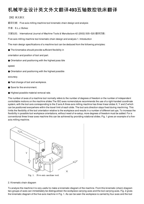
机械毕业设计英⽂外⽂翻译493五轴数控铣床翻译【附】英⽂原⽂翻译⽂献:Five-axis milling machine tool kinematic chain design and analysis作者:E.L.J. Bohez⽂献出处:International Journal of Machine Tools & Manufacture 42 (2002) 505–520 翻译页数:Five-axis milling machine tool kinematic chain design and analysis 1. IntroductionThe main design specifications of a machine tool can be deduced from the following principles:● The kinematics should provide sufficient flexibility inorientation and position of tool and part.● Orientation and positioning with the highest poss iblespeed.● Orientation and positioning with the highest possibleaccuracy.● Fast change of tool and workpiece.● Save for the environment.● Highest possible material removal rate.The number of axes of a machine tool normally refers to the number of degrees of freedom or the number of independent controllable motions on the machine slides.The ISO axes nomenclature recommends the use of a right-handed coordinate system, with the tool axis corresponding to the Z-axis.A three-axis milling machine has three linear slides X, Y and Z which can be positioned everywhere within the travel limit of each slide. The tool axis direction stays fixed during machining. This limits the flexibility of the tool orientation relative to the workpiece and results in a number of different set ups. To increase the flexibility in possible tool workpiece orientations, without need of re-setup, more degrees of freedom must be added. For a conventional three linear axes machine this can be achieved by providing rotational slides. Fig. 1 gives an example of a five-axis milling machine.2. Kinematic chain diagramTo analyze the machine it is very useful to make a kinematic diagram of the machine. From this kinematic (chain) diagram two groups of axes can immediately be distinguished: the workpiece carrying axes and the tool carrying axes. Fig. 2 gives the kinematic diagram of the five-axis machine in Fig. 1. As can be seen the workpiece is carried by four axes and the toolonly by one axis.The five-axis machine is similar to two cooperating robots, one robot carrying the workpiece and one robot carrying the tool.Five degrees of freedom are the minimum required to obtain maximum flexibility in tool workpiece orientation,this means that the tool and workpiece can be oriented relative to each other under any angle. The minimum required number of axes can also be understood from a rigid body kinematics point of view. To orient two rigid bodies in space relative to each other 6 degrees of freedom are needed for each body (tool and workpiece) or 12 degrees. However any common translation and rotation which does not change the relative orientation is permitted reducing the number of degrees by 6. The distance between the bodies is prescribed by the toolpath and allows elimination of an additional degree of freedom, resulting in a minimum requirement of 5 degrees.3.Literature reviewOne of the earliest (1970) and still very useful introductions to five-axis milling was given by Baughman [1]clearly stating the applications. The APT language was then the only tool to program five-axis contouring applications.The problems in postprocessing were also clearly stated by Sim [2] in those earlier days of numerical control and most issues are still valid. Boyd in Ref.[3] was also one of the early introductions. Bez iers’ book[4] is also still a very useful introduction. Held [5] gives a very brief but enlightening definition of multi-axis machining in his book on pocket milling. A recent paper applicable to the problem of five-axis machine workspace computation is the multiple sweeping using the Denawit-Hartenberg representation method developed by Abdel-Malek and Othman [6].Many types and design concepts of machine tools which can be applied to five-axis machines are discussed in Ref. [7] but not specifically for the five-axis machine.he number of setups and the optimal orientation of the part on the machine table is discussed in Ref.[8]. A review about the state of the art and new requirements for tool path generation is given by B.K. Choi et al. [9].Graphic simulation of the interaction of the tool and workpiece is also a very active area of research and a good introduction can be found in Ref. [10].4. Classification of five-axis machines’ kinematic structureStarting from Rotary (R) and Translatory (T) axes four main groups can be distinguished: (i) three T axes and two R axes; (ii) two T axes and three R axes; (iii) one T axis and four R axes and (iv) five R axes. Nearly all existing five-axis machine tools are in group (i). Also a number of welding robots, filament winding machines and laser machining centers fall in this group. Only limited instances of five-axis machine tools in group (ii)exist for the machining of ship propellers. Groups (iii)and (iv) are used in the design of robots usually with more degrees of freedom added.The five axes can be distributed between the workpiece or tool in several combinations. A first classification can be made based on the number of workpiece and tool carrying axes and the sequence of each axis in the kinematic chain.Another classification can be based on where the rotary axes are located, on the workpiece side or tool side. The five degrees of freedom in a Cartesian coordinates based machine are: three translatory movements X,Y,Z (in general represented as TTT) and two rotational movements AB, AC or BC (in general represented as RR).Combinations of three rotary axes (RRR)and two linear axes (TT) are rare. If an axis is bearing the workpiece it is the habit of noting it with an additional accent. The five-axis machine in Fig. 1 can be characterized by XYABZ. The XYAB axes carry the workpiece and the Z-axis carries the tool. Fig. 3 shows a machine of the type XYZAB , the three linear axes carry the tool and the two rotary axes carry the workpiece.5. Workspace of a five-axis machineBefore defining the workspace of the five-axis machine tool, it is appropriate to define the workspace of the tool and the workspace of the workpiece. The workspace of the tool is the space obtained by sweeping the tool reference point (e.g. tool tip) along the path of the tool carrying axes. The workspace of the workpiece carrying axes is defined in the same way (the center of the machine table can be chosen as reference point).These workspaces can be determined by computing the swept volume [6].Based on the above-definitions some quantitative parameters can be defined which are useful for comparison, selection and design of different types of machines.6.Selection criteria of a five-axis machineIt is not the objective to make a complete study on how to select or design a five-axis machine for a certain application. Only the main criteria which can be used to justify the selection of a five-axis machine are discussed.6.1. Applications of five-axis machine toolsThe applications can be classified in positioning and contouring. Figs. 12 and 13 explain the difference between five-axispositioning and five-axis contouring.6.1.1. Five-axis positioningFig. 12 shows a part with a lot of holes and flat planes under different angles, to make this part with a three axis milling machine it is not possible to process the part in one set up. If a five-axis machine is used the tool can process. More details on countouring can be found in Ref. [13]. Applications of five-axis contouring are: (i) production of blades, such as compressor and turbine blades; (ii) injectors of fuel pumps; (iii) profiles of tires; (iv) medical prosthesis such as artificial heart valves; (v) molds made of complex surfaces.6.1.2. Five-axis contouringFig. 13 shows an example of five-axis contouring, tomachine the complex shape of the surface we need to control the orientation of the tool relative to the part during cutting. The tool workpiece orientation changes in each step. The CNC controller needs to control all the five-axes simultaneously during the material removal process. More details on countouring can be found in Ref. [13]. Applications of five-axis contouring are: (i) production of blades, such as compressor and turbine blades; (ii) injectors of fuel pumps; (iii) profiles of tires; (iv) medical prosthesis such as artificial heart valves; (v)molds made of complex surfaces.6.2. Axes configuration selectionThe size and weight of the part is very important as a first criterion to design or select a configuration. Very heavy workpieces require short workpiece kinematic chains. Also there is a preference for horizontal machine tables which makes it more convenient to fix and handle the workpiece. Putting a heavy workpiece on a single rotary axis kinematic chain will increase the orientation flexibility very much. It can be observed from Fig. 4that providing a single horizontal rotary axis to carry the workpiece will make the machine more flexible. In most cases the tool carrying kinematic chains will be kept as short as possible because the toolspindle drive must also be carried.6.3.five-axes machining of jewelryA typical workpiece could be a flower shaped part as in Fig. 14. This application is clearly contouring. The part will be relatively small compared to the tool assembly. Also small diameter tools will require a high speed spindle. A horizontalrotary table would be a very good option as the operator will have a good view of the part (with range 360°). All axes as workpiece carrying axes would be a good choice because the toolspindlecould be fixed and made very rigid. There are 20 ways in which the axes can be combined in the workpiece kinematic chain (Section 4.2.1). Here only two kinematic chains will be considered. Case one will be a T T T R R kinematic chain shown in Fig. 15. Case two will be a R R T T T kinematic chain shown in Fig.16.For model I a machine with a range of X=300mmY=250 mm, Z=200 mm, C=n 360° and A=360°, and a machine tool table of 100 mm diameter will be considered. For this kinematic chain the tool workspace is a single point. The set of tool reference points which can be selected is also small. With the above machine travel ranges the workpiece workspace will be the space swept by the center of the machine table. If the centerline of the two rotary axes intersect in the reference point, a prismatic workpiece workspace will be obtained with as size XYZ or 300×250×200 mm3. If the centerlines of the two rotary axes do not intersect in the workpiece reference point then the workpiece workspace will be larger.It will be a prismatic shape with rounded edges. The radius of this rounded edge is the excentricity of the bworkpiece reference point relative to each centerline. Model II in Fig. 15 has the rotary axes at the beginning of the kinematic chain (R R T T T ). Here also two different values of the rotary axes excentricity will be considered. The same range of the axes as in model I is considered. The parameters defined in Section 5 are computed for each model and excentricity and summarized in Table 1. It can be seen that with the rotary axes at the end of the kinematic chain (model I), a much smaller machine tool workspace is obtained. There are two main reasons for this. The swept volume of the tool and workpiece WSTOOL WSWORK is much smaller for model I. The second reason is due to the fact that a large part of the machine tool workspace cannot be used in the case of model I, because of interference with the linear axes. The workspace utilization factor however is larger for the model I with no excentricity because the union of the tool workspace and workpiece workspace is relatively smaller compared with model I with excentricity e=50 mm. The orientation space index is the same for both cases if the table diameter is kept the same. Model II can handle much larger workpieces for the same range of linear axes as in model I. The rotary axes are here in the beginning of the kinematic chain, resulting in a much larger machine tool workspace then for model I. Also there is much less interference of the machine tool workspace with the slides. The other 18 possible kinematicchain selections will give index values somewhat in between the above cases.6.4. rotary table selectionTwo machines with the same kinematic diagram (T T R R T) and the same range of travel in the linear axes will be compared (Fig. 17). There are two options for the rotary axes: two-axis table with vertical table (model I), two-axis table with horizontal table (model II). Tables 2 and 3 give the comparison of the important features. It can be observed that reducing the range of the rotary axes increases the machine tool workspace. So model I will be more suited for smaller workpieces with operations which require a large orientation range, typically contouring applications. Model II will be suited for larger workpieces with less variation in tool orientation or will require two setups. This extra setup requirement could be of less importance then the larger size. The horizontal table can use pallets which transform the internal setup to external setup. The larger angle range in the B-axes 105 to +105, Fig. 17. Model I and model II T T R R T machines. compared to 45 to +20, makes model I more suited for complex sculptured surfaces, also because the much higher angular speed range of the vertical angular table. The option with the highest spindle speed should be selected and it will permit the use of smaller cutter diameters resulting in less undercut and smaller cutting forces. The high spindle speed will make the cutting of copper electrodes for die sinking EDM machines easier. The vertical table is also better for the chip removal. The large range of angular orientation, however, reduces the maximum size of the workpiece to about 300 mm and 100 kg. Model II with the same linear axes range as model I, but much smaller range in the rotation, can easily handle a workpiece of double size and weight. Model II will be good for positioning applications. Model I cannot be provided with automaticworkpiece exchange, making it less suitable for mass production. Model II has automatic workpiece exchange and is suitable for mass production of position applications. Model I could, however, be selected for positioning applications for parts such as hydraulic valve housings which are small and would require a large angular range.7.New machine concepts based on the Stewart platformConventional machine tool structures are based on Carthesian coordinates. Many surface contouring applications can be machined in optimal conditions only with five-axis machines. This five-axis machine structure requires two additional rotary axes. To make accurate machines, with the required stiffness, able to carry large workpieces, very heavy and large machines are required. As can be seen from the kinematic chain diagram of the classical five-axis machine design the first axis in the chain carries all the subsequent axes. So the dynamic responce will be limited by the combined inertia. A mechanism which can move the workpiece without having to carry the other axes would be the ideal. A new design concept is the use of a‘HEXAPOD’. Stewart [16] described the hexapod principle in 1965. It was first constructed by Gough and Whitehall [20] in 1954 and served as tire tester. Many possible uses were proposed but it was only applied to flight simulator platforms. Thereason was the complexity of the control of the six actuators. Recently with the amazing increase of speed and reduction in cost of computing, the Stewart platform is used by two American Companies in the design of new machine tools. The first machine is the VARIAX machine from the company Giddings and Lewis, USA. The second machine is the HEXAPOD from the Ingersoll company, USA. The systematic design of Hexapods and other similar systems is discussed in Ref. [17]. The problem of defining and determining the workspace of virtual axis machine tools is discussed in Ref. [18]. It can be observed from the design of the machine that once the position of the tool carrying plane is determined uniquely by the CL date (point + vector), it is still possible to rotate the tool carrying platform around the tool axis. This results in a large number of possible length combinations of the telescopic actuators for the same CL data.8.ConclusionTheoretically there are large number of ways in which a five-axis machine can be built. Nearly all classical Cartesian five-axis machines belong to the group with three linear and two rotational axes or three rotational axes and two linear axes. This group can be subdivided in six subgroups each with 720 instances.If only the instances with three linear axes are considered there are still 360instances in each group. The instances are differentiated based on the order of the axes in both tool and workpiece carrying kinematic chain.If only the location of the rotary axes in the tool and workpiece kinematic chain is considered for grouping five-axis machines withthree linear axes and two rotational axes, three groups can be distinguished. In the first group the two rotary axes are implemented in the workpiece kinematic chain. In the second group the two rotary axes are implemented in the tool kinematic chain.In the third group there is one rotary axis in each kinematic chain. Each group still has twenty possible instances.To determine the best instance for a specific application area is a complex issue. To facilitate this some indexes for comparison have been defined such as the machine tool workspace, workspace utilization factor, orientation space index, orientation angle index and machine tool space efficiency. An algorithm to compute the machine tool workspace and the diameter of the largest spherical dome which can be machined on the machine was outlined.The use of these indexes for two examples was discussed in detail. The first example considers the design of a five-axis machine for jewelry machining. The second example illustrates the selection of the rotary axes options in the case of a machine with the same range in linear axes.翻译题名:Five-axis milling machine tool kinematic chain design and analysis期刊与作者:E.L.J. Bohez出版社:International Journal of Machine Tools & Manufacture 42 (2002) 505–520●英⽂译⽂摘要:现如今五轴数控加⼯中⼼已经⾮常普及。
- 1、下载文档前请自行甄别文档内容的完整性,平台不提供额外的编辑、内容补充、找答案等附加服务。
- 2、"仅部分预览"的文档,不可在线预览部分如存在完整性等问题,可反馈申请退款(可完整预览的文档不适用该条件!)。
- 3、如文档侵犯您的权益,请联系客服反馈,我们会尽快为您处理(人工客服工作时间:9:00-18:30)。
7.1 INTRODUCTIONAfter lathes, milling machines are the most widely used for manufacturing applications. In milling, the workpiece is fed into a rotating milling cutter, which is a multi-point tool as shown in Fig. 7.1, unlike a lathe, which uses a single point cutting tool. The tool used in milling is called the milling cutter.Fig. 7.1Schematic diagram of a milling operationThe milling process is characterised by:(i)Interrupted cutting Each of the cutting edges removes materialfor only a part of the rotation of the milling cutter. As a result, the cutting edge has time to cool before it again removes material.Thus the milling operation is much more cooler compared to the turning operation. This allows for a much larger material rates.(ii)Small size of chips Though the size of the chips is small, in view of the multiple cutting edges in contact a large amount of material is removed and as a result the component is generally completed ina single pass unlike the turning process which requires a largenumber of cuts for finishing.(iii)Variation in chip thickness This contributes to the non-steady state cyclic conditions of varying cutting forces during the contact of the cutting edge with the chip thickness varying from zero to maximum size or vice versa. This cyclic variation of the force can excite any of the natural frequencies of the machine tool system and is harmful to the tool life and surface finish generatedA milling machine is one of the most versatile machine tools. It is adaptable for quantity production as well as in job shops and tool rooms. The versatility of milling is because of the large variety of accessories and tools available with milling machines. The typical tolerance expected from the process is about ±0.050 mm.7.2 TYPES OF MILLING MACHINESTo satisfy various requirements milling machines come in a number of sizes and varieties. In view of the large material removal ratesmilling machines come with a very rigid spindle and large power. The varieties of milling machines available are:(i) Knee and Column type(a) horizontal(b) vertical(c) universal(d) turret typeThese are the general purpose milling machines, which have a high degree of flexibility and are employed for all types of works including batch manufacturing. A large variety of attachments to improve the flexibility are available for this class of milling machines.(ii) Production (Bed) type(a) simplex(b) duplex(c) triplexThese machines are generally meant for regular production involving large batch sizes. The flexibility is relatively less in these machines which is suitable for productivity enhancement.(iii) Plano millersThese machines are used only for very large workpieces involving table travels in meters.(iv) Special type(a) Rotary table(b) Drum type(c) Copy milling (Die sinking machines)(d) Key way milling machines(e) Spline shaft milling machinesThese machines provide special facilities to suit specific applications that are not catered to by the other classes of milling machines.7.2.1 Knee and Column Milling MachinesThe knee(升降台) and column type is the most commonly used machine in view of its flexibility and easier setup. A typical machine construction is shown in Fig. 7.2 for the horizontal axis. The knee houses the feed mechanism and mounts the saddle and table. The table basically has the T-slots running along the X-axis for the purpose of work holding. The table moves along the X-axis on the saddle while the saddle moves along the Y-axis on the guide ways provided on the knee.The feed is provided either manually with a hand wheel or connected for automatic by the lead screw, which in turn is coupled to the main spindle drive. The knee can move up and down (Z-axis) on a dovetail provided on the column.Fig. 7.2 Horizontal knee and column type milling machineThe massive column at the back of the machine houses all the power train including the motor and the spindle gearbox. The power for feeding the table lead screw is taken from the main motor through a separate feed gearbox. Sometimes a separate feed motor is provided for the feed gearbox as well.While the longitudinal and traverse motions are provided with automatic motion, the raising of the knee is generally made manually.The spindle is located at the top end of the column. The arbour used to mount the milling cutters is mounted in the spindle and is provided with a support on the other end to take care of the heavy cutting forces by means of an overarm with bearing. As shown in Fig.7.2 the overarm extends from the column with a rigid design. The spindle nose has the standard Morse taper of the suitable sizedepending upon the machine size.The milling cutters are mounted on the arbour at any desired position, the rest of the length being filled by standard hardened collars of varying widths to fix the position of the cutter. The arbour is clamped in the spindle with the help of a draw bar and then fixed with nuts.Milling machines are generally specified on the following basis:(i) Size of the table, which specifies the actual working area on the table and relates to the maximum size of the workpiece that can be accommodated.(ii) Amount of table travel, which gives the maximum axis movement that is possible.(iii) Horse power of the spindle, which actually specifies the power of the spindle motor used. Smaller machines may come with 1 to 3 hp while the production machines may go from 10 to 50 hp.Another type of knee and column milling machine is the vertical axis type. Its construction is very similar to the horizontal axis type, except for the spindle type and location.The vertical axis milling machine is relatively more flexible (Fig. 7.4) and suitable for machining complex cavities such as die cavities in tool rooms. The vertical head is provided with a swiveling facility in horizontal direction whereby the cutter axis can be swivelled. This isuseful for tool rooms where more complex milling operations are carried out.The spindle is located in the vertical direction and is suitable for using the shank mounted milling cutters such as end mills, In view of the location of the tool, the setting up of the workpiece and observing the machining operation is more convenient.Fig, 7.3 Vertical knee and column type milling machineFig.7.4 Some of the milling operations normally carried out on vertical axis machinesThe universal machine has the table which can be swivelled in a horizontal plane at about 45o to either the left or right. This makes the universal machine suitable for milling spur and helical gears as well as worm gears and cams.7.2.2 Bed Type Milling MachineIn production milling machines it is desirable to increase the metal removal rates. If it is done on conventional machines by increasingthe depth of cut, there is possibility of chatter. Hence another varietyof milling machines named as bed type machines are used which are made more rugged and are capable of removing more material. The ruggedness is obtained as a consequence of the reduction in versatility.The table in the case of bed type machines is directly mounted on the bed and is provided with only longitudinal motion.The spindle moves along with the column to provide the cutting action. Simplex machines (Fig. 7.5) are the ones with only one spindle head while duplex machines have two spindles (Fig. 7.6). The two spindles are located on either side of a heavy workpiece and remove material from both sides simultaneously.Fig. 7.5 Simplex bed type milling machineFig. 7.6 Duplex bed type milling machine7.3 MILLING CUTTERSThere are a large variety of milling cutters available to suit specific requirements. The versatility of the milling machine is contributed toa great extent by the variety of milling cutters that are available.7.3.1 Types of Milling CuttersMilling cutters are classified into various types based on a variety of methods.(i) Based on construction:(a) Solid(b) Inserted tooth typeBased on mounting:(a) Arbor mounted(b) Shank mounted(c) Nose mountedBase on rotation:(a) Right hand rotation (counter clockwise)(b) Left hand rotation (clockwise)Based on helix:(a) Right hand helix(b) Left hand helixMilling cutters are generally made of high speed steel or cemented carbides. The cemented carbide cutters can be of a brazed tip variety or with indexable tips. The indexable variety is more common since it is normally less expensive to replace the worn out cutting edges than to regrind them.Plain milling cutters These are also called slab milling cutters and are basically cylindrical with the cutting teeth on the periphery as shown in Fig. 7.7. These are generally used for machining flat surfaces.Fig. 7.7 Arbor mounted milling cutters for general purposeLight duty slab milling cutters generally have a face width, which is small of the order of 25 mm. They generally have straight teeth and large number of teeth.Heavy duty slab milling cutters come with a smaller number of teeth to allow for more chip space. This allows taking deeper cuts and consequently high material removal rates.Helical milling cutters have a very small number of teeth but a large helix angle. This type of cutter cuts with a shearing action, which can produce a very fine finish. The large helix angle allows the cutter to absorb most of the end load and therefore the cutter enters and leaves the workpiece very smoothly.Side and face milling cutters These have the cutting edges not only onthe face like the slab milling cutters, but also on both the sides. As aresult, these cutters become more versatile since they can be used for side milling as well as for slot milling.Staggered tooth side milling cutters are a variation where the teeth are arranged in an alternate helix pattern. This type is generally used for milling deep slots, since the staggering of teeth provides for greater chip space.Another variation of the side and face cutter is the half side milling cutter, which has cutting edges only on one side. This arrangement provides a positive rake angle and is useful for machining on only one side. These have a much smoother cutting action and a long tool life. The power consumed is also less for these cutters.Fig. 7.8Special forms of arbor mounted milling cuttersSlitting saws The other common form of milling cutters in the arbor mounted category is the slitting saw. This is very similar to a saw blade inappearance as well as function. Most of these have teeth around the circumference while some have side teeth as well. The thickness of these cutters is generally very small and is used for cutting off operations or for deep slots.Special form cutters In addition to the general type of milling cutters described above, there are a large number of special form milling cutters available which are used for machining specific profiles.Angular milling cutters are made in single or double angle cutters for milling any angle such as 30, 45 or 60o Form relieved cutters are made of various shapes such as circular, corner rounding, convex or concave shapes.T-slot milling cutters are used for milling T-slots such as those in the milling machine table. The central slot is to be milled first using an end mill before using the T-slot milling cutter. Woodruff key seat milling cutters are used for milling as the name suggests, woodruff key seats Some other special form cutters are dovetail milling cutters and gear milling cutters.End mills These are shank mounted as shown in Fig. 7.9 and are generally used in vertical axis milling machines. They are used for milling slots, key ways and pockets where other type of milling cutters cannot be used. A depth of cut of almost half the diameter can be taken with the end mills.The end mills have the cutting edge running through the length of the cutting portion as well as on the face radially up to a certain length. The helix angle of the cutting edge promotes smooth and efficient cutting even at high cutting speeds and feed rates. High cutting speeds(转速?) are generally recommended for this type of milling cutters.Fig. 7.9 Shank mounted milling cutters and various types of end mills There are a large variety of end mills. One of the distinctions is based on the method of holding, i.e., the end mill shank can be straight or tapered. The straight shank is used on end mills of small size and held in the milling machine spindle with the help of a suitable collet. The tapered shank can be directly mounted in the spindle with the help of the selfholding taper. If the taper is small compared to the spindle taper, then an adopter accommodating both the tapers is used.The end teeth of the end mills may be terminated at a distance from the cutter center or may proceed till the center (Fig. 7.9 f). Those with the cutting edge up to the center are called slot drills or end cutting end mills since they have the ability to cut into the solid material (Fig. 7.9 g). The other type of end mills which have a larger number of teeth cannot cut into solid material and hence require a pilot hole drilled before a pocket is machined.The cutting edge along the side of an end mill is generally straight and sometimes can be tapered by grinding on a tool and cutter grinder such that the draft required for mould and die cavities can be automatically generated.第七章铣削7.1介绍除了车床,铣床是制造应用中最广泛使用的。