ND模块详细版使用说明
ND889A操作说明书
日精230MHz专业数传电台ND886A/ND889A(使用前请仔细阅读本说明书)©Copyright 2004 byAll rights reservedPrinted in Japan一、ND886A/ND889A外观图及性能特点介绍■尺寸长×宽×高= 44×135×137mm※注:ND886A/ND889A已获得国家信息产业部无线电管理局核发的“无线电发射设备型号核准证”,核准代码分别为:ND886A:CMII ID:2002FJ0359ND889A:CMII ID:2002FJ0712■全新的设计理念:⊙所有收发射频电路采用目前最先进的低噪声场效应(FET)电路设计,高灵敏度、高效率。
⊙完全切合用户需求的专业的线路设计及接口配置,是真正意义上的数传电台,数话兼容。
⊙适用于各类严酷的工作环境,工作温度范围达-40℃~+70℃,真正的工业级产品。
⊙主要功能及参数可通过编程灵活设置,安装操作非常简便;体积紧凑、坚固,屏蔽及散热性极佳。
⊙电台内部预留多个接口,方便用户进行二次开发,内置及外置MODEM、话筒等配套产品一应俱全。
⊙极低的守候电流及发射电流,特别适合于野外需要太阳能电池供电的应用场合。
⊙开放的技术体系,提供先进的编程软件及测试软件,用户可在很短的时间内掌握使用方法。
■广泛的应用领域:日精数传电台/模块适用于各类点对点,一点对多点的无线数据传输系统,如电力负荷监控、配网自动化、水文水情测报、自来水管网监测、城市路灯监控、防空警报控制、铁路信号监控、热网监控、输油供气管网监测、GPS定位、集中抄表、地震测报、电子吊称、自动报靶、防火防盗、环境监测等工业自动化系统。
■功能特点:⊙223—235MHz工作频段内保证各项技术指标,无需调整⊙ 16(或48)个半双工信道,电脑写频,各频道的功率等参数可以独立设置为不同的值⊙ 真正的工业级产品,工作温度范围-40℃∽+70℃,频率稳定度达到±1.5PPM⊙ 收、发射机均采用最先进的FET低噪声放大电路,灵敏度高、杂波小、发热少⊙ ND886A及ND889A的最大功率分别可达15W(FET机型)及28W,物超所值⊙ 5级发射功率、“长发”时限、频响特性及工作模式等可编程设置⊙可遥控改变频道、发射功率及静噪开启灵敏度等参数(此项功能由软件版本决定)⊙发射机“长发”保护、电源逆接保护、电源及天线输入端浪涌保护等多项保护功能⊙耗电省,守候电流小于50mA,节电模式下守候电流≤10mA⊙铝压铸机身,散热快,屏蔽好,抗干扰能力强⊙数话兼容、数传可优先;面板带有DATA收、发指示灯⊙双VCO设计,发射机起动时间小于20ms(FET机型),收发转换快⊙体积紧凑(44×135×137mm)、结构坚固、安装方便⊙可内置或外置多种类型的MODEM,带标准DB-9型I/O口,最高速率19.2Kbps⊙ 极低的误码率: ≤10-7 @-105dBm 2.4kbps。
Rainharvest系统设备模块操作指南说明书

Operation & Installation InstructionsEQUIPMENT MODULESTable of ContentsEmulator Module (1)Remote Alarm Module (2)4-20 mA Module (3)Solonoid Module (4)Water Quality Monitor Module (8)EMULATOR MODULEMODEL # MOD-EMU-RFThe Emulator module comes with a maleIEP connection (Infinite ExpandabilityPort). Prior to start-up, first ensure all thetoggle switches for the “Module Alarms”and “Lamp Alarm” are in the OFF (toggleup) position. Plug the Emulator connectorinto the IEP on the RAINHARVESTSYSTEMS controller, then plug in thecontroller power cord.To Emulate a particular module failure,toggle the corresponding switch to theON (toggle down) position. The alarmcan be cleared by returning the switch toits OFF (toggle up) position. The devicealso can emulate the UV intensity reported by a UV sensor module. Turning the right “UV” knob in the clockwise direction will increase the intensity, while turning it counterclockwise will decrease the intensity. Please note that to see all the capabilities of the sensor, you will need to cycle the intensity through the range of 49 through 66 %. The “Days Remaining” cycle can also be adjusted by turning the left “Days” knob.MOD-EMU-RFRF seriescontrollersRF-C seriescontrollersIEPconnectionIEPconnection1|P a g e2|P a g eREMOTE ALARM MODULEMODEL # MOD-RAM-RFThe Remote Alarm module comes with both a male and female IEP connection (Infinite Expandability Port). To initiate the module simply plug the male plug into the IEP on the Standard or High Output controller, or into any other RAINHARVEST SYSTEMS module that contains an IEP (sensor, 4-20 mA module, solenoid module, etc.) and then restart the system.The Remote Alarm module is a pair of dry contacts and can be used to connect the controller to a PLC based system, an alarm buzzer (or light), or an “OK” light. The contacts are rated for 230VAC 1A. If your device draws more current, please use the module to switch a relay with contacts rated for the device you wish to use.“OK”LightPower Supply 24 VDC/110V./230V.“FAIL” Light/BuzzerAutodialerPower Supply 24 VDC/110V./230V.remote alarm moduleCom OK Fault remote alarm module ComOKFault Sensor IEP InstallationIEP connectionRF series controllers RF-C series controllers IEP connectionIEP connection3|P a g e4-20 mA MODULEMODEL # MOD-420-RFThe 4-20 mA module comes with both a male and female IEP connection (Infinite Expandability Port). To initiate the module simply plug the male plug into the IEP on the controller, or into any other RAINHARVEST SYSTEMS module that contains an IEP (sensor, remote alarm, solenoid module, etc.)Connect “LOOP” Connections as follows:LOOP Specifications Power Supply: Min 5 voltsMax 30 voltsPower SupplyPLC orData LoggerSensor IEP InstallationconnectionRF series controllers RF-C series controllers IEP connectionIEP connectionSOLENOID MODULEMODEL # MOD-SOL1-RFLOCATIONStep 1) Find a suitable location on the wall for thesolenoid module. The module must be installed closeenough to the controller, or the UV sensor to be ableto plug in the male IEP connector. The module mustalso be installed close enough to the actual solenoidvalve and this distance will be dependent on the cordlength of the particular solenoid valve that is used.Step 2) Pick a location for the solenoid valve andinstall as per the manufacturer’s directions. Thesolenoid module requires bare leads, so if thesolenoid cable has a plug attached, remove the plugand strip the wires to a suitable length.INSTALLATIONStep 1) Make sure the solenoid valve cable is NOT plugged into the electrical outlet. Insert the solenoid valve cable through the center hole of the middle strain relief. Connect the three electrical wires to the terminal block that is marked “SOLENOID” (see Fig. 1). Connect the ground wire in the position marked “GND”, the line voltage wire in the position marked “L1” and the neutral wire in the position marked “N”. Typical wire colour configurations are marked directly on the circuit board to the left of the SOLENOID terminal block to aid in this process (see Fig.2) If you are unsure of the correct wiring configuration for you particular solenoid valve, please contact an approved electrical contractor. Once all the line voltage connectionshave been made, tighten the strain relief nut to secure the cable to the solenoid module.Figure 2Wiring Colour GuideFigure 1Solenoid Wire Installation4|P a g eStep 2) Plug the solenoid valve into the applicable electrical outlet. At this stage, the functionality of the solenoid valve can be tested by pressing the solenoid test button located on the upper left of the circuit board. Manually depressing (and holding) this button will complete the electrical circuit and will open the normally closed solenoid valve. You should be able to hear the activation of the solenoid valve at this stage to ensure the valve is functioning properly (see Fig. 3).Step 3) Make sure your UV controller is unplugged from thepower source. Once all these connections have been made, affix the male IEP plug of the solenoid module cable into the IEP port on the controller, or any other available IEP port such as the UV sensor, 4-20 mA module or remote alarm module. It does not matter which IEP port any module is attached to, as long as they are attached.Figure 3Solenoid Test ButtonOPERATIONStep 1) Plug the RAINHARVEST SYSTEMS controller into the power source and make sure the solenoid module is activated on the controller. During the start-up sequence, the SOLENOID MODULE screen will indicate a “initialized” when the module is activated properly (see Fig. 4).Figure 4 Solenoid ActivationScreens Sensor IEP InstallationIEPconnection RF seriescontrollersRF-C seriescontrollersIEPconnectionIEPconnection5|P a g e6|P a g eStep 2) The controller will only notify you when there is a failure mode whereby the solenoid module (and connected solenoid valve) will be activated. On the RF5 or RF6-C systems, the solenoid module will be activated (shutting off the flow of water) upon LAMP FAILURE (see Fig. 5). To remedy this, replace the UV lamp and restart the system as per the directions outlined in the Owner’s Manual.Step 3) On the RF5 or RF6-C system where a UV sensor is installed, the solenoid module will be activated (shutting off the flow of water) upon a LOW UV condition (less than 50%) (see Fig. 6). To remedy this, you will need to address the reason for this low UV condition which may be due to a dirty UV sensor and quartz sleeve, a lamp that is not emitting enough UV energy, or a change in the water quality. Please refer to the UV systems Owner’s Manual for corrective action procedures.Figure 5LAMP FAILURE ScreenStep 4) To determine what position the solenoid valve is currently in, the solenoid module incorporates three lights on the circuit board (see Fig. 7). When the solenoid is in the OPEN position a green light will appear on the circuit board beside the word “OPEN”. When the valve is CLOSED, a red light will appear on the circuit board beside the word “CLOSED”. And when the solenoid is in an OVERRIDE position, an amber light will appear on the circuit board beside the words “OVERRIDE ON”.Figure 6LOW UV ScreensFigure 7Solenoid Status(Colour)Boil Water Advisory: If any failure occurs on a RAINHARVEST SYSTEMS UV system, the water must not be used for human consumption until the system is returned to a safe operational mode. If the water is used for human consumption during this period, the water must beboiled (minimum 20 minutes at a full boil) prior to consumption.EMERGENCY BYPASSIn a case where the solenoid valve has been activated (valve is closed and no water is allowed to flow), the solenoid module has the ability to bypass the solenoid valve in case of an emergency need of water. To initiate this bypass, depress the button labeled “OVERRIDE” located in the lower left portion of the circuit board (see Fig. 8)7|P a g eFigure 8Solenoid BypassButtonOnce this button has been pressed, the system will remain in this override mode regardless of whether or not the condition causing the solenoid activation has been remedied or not. To reset the system, the power to the controller must be shut off and restarted. While in this override mode the controller will intermittently display a red “SOLENOID OVERRIDE” screen (see Fig. 9).Figure 9SOLENOID OVERRIDEScreenDISABLING EMERGENCY BYPASSIn certain regulated applications, the availability , and use, of the emergency bypass feature may be in violation of the local, state/provincial codes. If this is the case, the bypass feature can easily be disabled by physically removing the bypassbutton. To accomplish this, carefully use a pair of needle nose pliers and physically remove the actual bypass button (marked“OVERRIDE”) from the circuit board .Figure 10SOLENOID FAILUREScreenOTHER FAILURE MODESIn the event there is an issue with the solenoid connection from the IEP cable to the controller, the system will register a “SOLENOIDFAILURE” screen on the controller (see Fig. 10).CAUTION: BEFORE PERFORMING ANY WORK ON THE SOLENOID MODULE, THE POWER CORD MUST BE DISCONNECTED FROM ITS POWER SOURCE (WALL PLUG).8|P a g eWATER QUALITY MONITOR MODULEMODEL # MOD-SHERPA-GThe module comes with a Transmitter and a Remote Display. The Transmitter connects to a standard output and high output controller and transmits the controller’s status wirelessly to the Remote Display. Every Transmitter and Remote Display is paired together and usesencryption to create a reliable and secure communication link between the two devices. Every Transmitter supports up to five Remote Displays. Additional Remote Displays can be purchased and installed separately. Refer to ‘Pairing an Additional Remote Display’ for additional Remote Display installation.Sensor IEP InstallationIEPconnectionRF series controllers RF-C series controllers IEPconnectionIEPconnectionInstallationStep 1) Power off the UV system controller.Step 2) P lug the male plug of the Transmitter into the IEP (Infinite Expandability Port) onthe controller, or into any other module that contains an IEP (sensor, 4-20 mA module, solenoid module, etc.) and then restart the system Note 1.Step 3) T o receive the UV systemcontroller’s status on the Remote Display, plug the AC/DC wall adapter into the Power Port on the Remote Display (5V Max) and slide the switch to the ON position.Back of Remote DisplayTransmitterRemote Display50m/164ft(Note 2)Good CautionAlarmWater QualityMonitorOperationNOTE 1: Not Compatible with MOD-RAM-RF. The module gets detected as a “Remote Alarm” on standard output and high output controllers during the start-up sequence.NOTE 2: The Wireless Range can vary based on the installation environment; objects, walls and metal obstacles can interfere and degrade the wireless signal. Best suited for residential applications.Pairing an Additional Remote DisplayTo pair an additional Remote Display to a currently installed Transmitter:Step 1)P ower ON the Additional Remote Display within 5m (15ft) proximity to the transmitter; by simply plugging the AC/DC wall adapter into the Power Port onthe Remote Display and sliding the switch to the ON position.Step 2)T he Remote Display performs self-pairing with the local transmitter. Once paired the Communication LED on the Remote Display will turn OFF and a Status LEDwill turn ON.Step 3) Once pairing is complete, relocate the Remote Display to any location2.9|P a g ePN#910386Version Date: 04-2019RainHarvest Systems, LLC 4475 Alicia LaneCumming, GA 30028Tel: *********************。
Nanodrop分光光度计20002000C中文操作使用说明

Nanodrop 2000/2000C 分光光度计V1.0 用户守则基因有限公司仪器应用技术支持亲爱的用户,您好!非常感谢您选购我公司代理的仪器。
我们将竭诚为您提供优质的售后服务及免费的专业应用培训。
为了更好地进行仪器的应用培训,我们根据您所选购的仪器特点,将需要您配合准备的工作敬告如下:1. 应用培训内容:仪器操作培训和软件应用培训。
仪器操作培训包括:仪器的操作、维护和仪器使用注意事项。
软件应用培训包括:用户本次所购买的同仪器配套的所有软件的软件应用培训。
2. 培训时间:仪器正式安装调试后,本公司2周内派出专业技术人员进行应用培训。
3. 应用培训中所需准备的试剂、耗材和仪器均需由用户提供,并在系统培训开始前准备好。
我公司将指派专业技术人员免费进行应用培训。
4. 用户签收售后服务工作报告后,基因公司正式的系统培训内容即完成。
您以后在使用的过程中有任何疑问都可以向我们咨询,我们非常乐意为您们解决应用上遇到的问题。
5. 在仪器的使用过程中,无论遇到您认为多么微小或繁琐的问题,请您及时和我们联系,一个及时的通知能节约您的时间,也能帮助我们更好的了解仪器和软件。
6. 联系我们时请您提供:仪器型号、软件名称,版本、错误代码、实验目的、操作系统(98/2k/xp/NT)、维修历史等相关资料。
本守则提的信息仅供参考,本守则包含的所有信息应该是正确和完整的。
如果对本守则中的描述有疑问,请参考厂家的英文操作说明。
如果由于您的不正当使用而对仪器造成损坏或者导致仪器的性能损伤,本公司将不会对此负责。
1.仪器介绍仪器描述Thermo Scientific NanoDrop 2000/2000C 分光光度计可以检测0.5-2ul 的样本,而且检测是非常高的准确性和重复性。
ND2000C 分光光度计不仅提供了NanoDrop 样品保留专利技术的便利性,也可以使用传统的比色皿来进行样本检测。
样本保留系统应用了表面张力来把样本保留在两根检测光纤中间,这使得仪器可以检测较高浓度的样本而不用稀释。
ND523操作手册
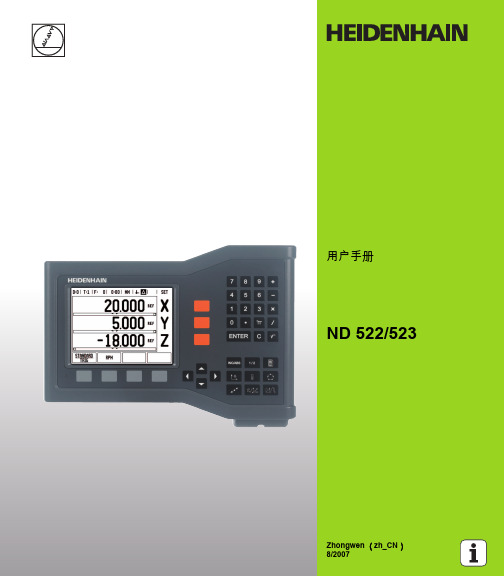
图 I.5
直线位置光栅尺,在此为 X 轴
14
I 操作手册
编码器上通常有一个或多个参考点 (参见 图 I.6) , ND 522/523 的参 考点计算” 功能用这些参考点在断电后重新建立原点位置。参考点有 两种:固定的和带距离编码的。 带距离编码参考点的编码器,其参考点通过特别编码方式相距一定距 离,它使 ND 522/523 只需使用整个光栅尺上的任意两个参考点就能 重新建立上个原点。 因此,采用这种结构的光栅尺,操作人员在任何 位置处只需移动很短距离就能当 ND 522/523 恢复供电时,重新建立 原点。 固定参考点的编码器有一个参考点或固定间距的多个参考点。要重新 正确地建立原点,在参考点计算过程中,必须用上个参考点计算时所 用的完全相同的参考点。 如果设置原点前没有执行参考点回零操作,那么恢复供电 后也无法重新恢复已有原点。
8
II 技术信息 ..... 67
II – 1 系统安装和电气连接 ..... 68 整个系统包括 ..... 68 附件 ..... 68 ND 522/523 显示单元 ..... 68 固定位置 ..... 68 系统安装 ..... 68 电气连接 ..... 68 电气参数要求 ..... 69 环境 ..... 69 连接电源接头 (参见 图 II.1) ..... 69 预防性维护 ..... 69 连接编码器 ..... 70 编码器输入接口的针脚编号 ..... 70 II – 2 系统设置 ..... 71 系统设置参数 ..... 71 编码器设置 ..... 71 显示配置 ..... 72 连接 ..... 72 误差补偿 ..... 72 线性误差补偿 ..... 73 非线性误差补偿 ..... 73 配置补偿表 ..... 74 读图 ..... 74 查看补偿表 ..... 74 导出当前补偿表 ..... 74 导入新补偿表 ..... 74 反向间隙补偿 ..... 75 计数器设置 ..... 76 诊断 ..... 76 键盘测试 ..... 76 显示测试 ..... 76 II – 3 编码器参数 ..... 77 HEIDENHAIN 公司的直线光栅尺设置举例 ..... 77 HEIDENHAIN 公司的旋转编码器设置举例 ..... 77 HEIDENHAIN 公司的角度编码器设置举例 ..... 77
森兰CGCC1702模块使用说明书V3.0

数据传输模块(DM)的安装版本号:CGCC1702V3.01.1概述DM必须正确安装方可达到设计的功能,通常设备的安装必须在我公司认可合格的工程师指导下进行。
0注意事项:请不要带电安装DM。
1.2安装与电缆连接外形尺寸:DM封装在金属机壳内,可独立使用,两侧或两头有固定的孔位,方便用户安装,具体的固定尺寸参见下图。
用户的数据电缆接口在模块的底部接入,考虑到连接的可靠性,我们配备了安装附件,固定用户数据电缆,提高连接的可靠性。
安装电缆:数据传输模块(DM)采用16PIN芯间距为3.81mm的单列端子接口。
管脚定义如下图:数据传输模块(DM)工作说明2.2、指示灯的说明指示灯状态说明亮设备电源正常电源(Power)灭设备未上电闪烁有数据收发通信(Act)灭没有数据收发1秒1次,(0.25秒亮,0.75秒灭)处于AT态,正在进行PIN检测2秒1次,(0.5HZ方波,1秒亮,1秒灭)处于AT态,正在进行信号检测2秒1次(0.25秒亮,1.75秒灭)处于AT态,正在进行网络附着/拨号/ppp握手在线(Online)4秒闪1次(0.25HZ方波,0.25秒亮,3.75秒灭)已登陆GPRS网络,并与中心建立连接森兰变频器连接DM 的方法CGCC1702V3.01.森兰SB200型变频器1.1通讯连接变频器的通讯为内置RS485通讯方式,通讯线连接为:485+、485—、GND (地) 1.2通讯参数连接好通讯后需要修改变频器如下的参数方可正常通讯 序号 参数 名称设置值 说明1 FF-00 通讯协议选择 0(默认值) MODBUS2 FF-01 通讯数据格式 1 8E13 FF-02 波特率选择 3(默认值) 96004 FF-03 通讯地址选择1(默认值)5 FF-04 通讯超时检出时间 10.0s6 FF-05 本机应答延时 5ms7 FF-06 通讯超时动作 0 不动作 8FF-08通讯设定频率比例 1.0001.3 DTU 通讯参数9600,8E11.4 注意:通讯参数修改后需要把变频器停电,再上电后参数才有效。
ND900定位器

ND9000定位器用户界面可用于监控,也可用于对定位器的组态和设定。
用户界面由两行LCD和四个按键(C、-、+、←)组成,特殊状态下可显示用户组态内容。
见图91.测量监控设备送电后,进入测量值监控状态显示测量值。
下表为默认的测量值单位及可选单位值。
如通过现场总线组态软件FIELDCARE改为美标(US)单位后,则默认压力单位自动改为psi,温度单位改为℉。
按(←)键可即时改变单位。
LCD上行显示当前单位,按住(←)键时同时按(+)或(-)键来选择新的单位,松开按键后即激活(有效输入情况下)。
在1小时内未对定位器进行各种操作,则LCD显示屏滚动显示各测量值。
见图102.快速设置快速设置可对ND-9100F定位器、执行机构、调节阀配置的主要参数进行快速浏览,在核对参数后,最好进行阀门的行程校验。
同时按下(C)键和(←)键可进入快速设置菜单,再按(C)键可取消任何操作。
取消后回到上级用户界面。
主要组态参数如下,详细内容见4.5部分阀门类型 VTYP执行机构形式 ATYP定位器故障位置 PFA阀旋转方向 ROT阀死区 AO改变任一参数后必须重新进行整阀的校验,详细内容见6部分。
见图113. 组态该用户界面是一菜单结构,在测量监控状态下,同时按(+)键和(-)键就进入组态菜单。
然后再按(+)键或(-)键来选择相应菜单。
见图124.模式菜单若用户要改变阀门的操作模式,可在MODE选择行按(←)键,此时MODE 会闪烁。
再按(+)键或(-)键可改变当前操作模式,最后按(←)键确认所选择的模式,有二个操作模式可供选择。
4.1 自动(AUTO)在自动模式下,定位器接受总线上的信号控制阀们的位置。
该模式为正常的工艺服务时使用。
发生信号故障后,定位器会采用在AUTO状态下的输入信号,使阀门保持原位。
4.2 手动(MAN)在手动模式下,可通过手按(+)键或(-)键来控制阀门的位置。
由于手操的阀位不保存到定位器的内存中,所以当信号故障后阀门也不会返回原来位置,但此时可通过手操(+)或(-)回到该阀位。
Wi-Fi智能多位控制LED灯光模块说明书

Description3-way, multi-location 120V/AC, 60HzDesign features• Does not control a load•Compatible with Wi-Fi smart universal dimmer for multi-location control (EWDF30)•LED indicator system alerts if the device is not connected to the Wi-Fi smart universal dimmer • Neutral wire required for installation•Dimmable seven step white LED display alongside push pad indicates selected light level - even in full daylight (coordinates light level status with connected LED indicator system alerts if the device is not connected to the Wi-Fi smart dimmer)• Adjust how long lights stay on to allow for a safe, convenient exit •Available in 8 different colors including metallic finishesProject Name:Prepared By:Project Number:Date:Catalog Number:Type:Compliances, specifications and availability are subject to change without notice.EWACDT able 1. Accessory dimmerRating DescriptionColor suffixCatalog no.AV/AC Hz-12060Accessory dimmer compatible with Wi-Fi smart dimmer (EWFD30)W, C2, C6, C7EWACD__Accessory dimmer2EATON /connectedhomeTechnical DataEffective April 2023Accessory dimmer can be wired with Wi-Fi smart dimmer (EWFD30) to provide multi-location ON/OFF/BRIGHT/DIM control. Accessory dim-mer will need to be wired with the load controlling dimmer using a single 3-way wire.ApplicationProject Name:Prepared By:Project Number:Date:Catalog Number:Type:Compliances, specifications and availability are subject to change without notice.Catalog No.EWACDPerformanceRating: 120V/AC, 60HzInstallation & programming For installation and programming the device, see the Accessory Dimmer Quick Start Guide included with product.Testing & code compliance cULus Listed 6B28. NOM Certified.TerminationsAccessory dimmers have four screw terminals for line, ground, neutral and 3-way Material characteristics Flammability: Meets UL94 requirements; V2 rated Temperature rating: 32°F to 104°F (0°C to 40°C)Warranty2-year limited product warrantyT able 2. SpecificationsT able 3. Color ordering informationFor ordering devices, include Catalog No. followed by the Color Suffix: W (White),C2 (Color Change Kit: LA, W, V), C6 (Color Change Kit: W, RB, SG), C7 (Color Change Kit: B, BK, GY)Figure 1. EWACD Product dimensionsTwo location control (requires one Wi-Fi smart dimmer and one accessory dimmer EWACD)EWACDAccessory dimmerC2 Color KitLA (Light Almond), W (White),V (Ivory)C7 Color KitB (Brown), BK (Black), GY (Gray)C6 Color KitRB (Oil Rubbed Bronze), W (White),SG (Silver Granite)Technical DataEffective April 2023Project Name:Prepared By:Project Number:Date:Catalog Number:Type:Certifications & compliancesKEY:cULusNOMRelated productsCompliances, specifications and availability are subject to change without notice.WallplatesPJS26, PJS262Wi-Fi smart productsEWFD30, EWFSW15, EWFTRCR15Multiple Locations using up to four accessory dimmers (EWACD)Accessory dimmerElectrical Sector 1123 Hwy 74 SPeachtree City, GA 30269United States /WifiSmartElectrical Sector Canada Operations 5925 McLaughlin RoadMississauga, Ontario, L5R 1B8CanadaEatonCanada.ca/WifiSmartElectrical Sector Mexico Operations Carr. Tlalnepantla -Cuautitlan Km 17.8 s/n Col. Villa Jardin esq.Cerrada 8 de MayoCuautitlan, Mexico CP 54800Mexico Eaton.mx/WifiSmartEaton1000 Eaton Boulevard Cleveland, OH 44122United States Eaton is a registered trademark. All other trademarks are property of their respective owners.© 2023 EatonAll Rights Reserved Printed in USAPublication No. TD610143EN April 2023。
ND模块使用说明

N D模块使用说明Document serial number【NL89WT-NY98YT-NC8CB-NNUUT-NUT108】N588D MP3 模块说明与使用(技术交流文档)1、N588D MP3 语音芯片模块功能N588D语音芯片是一款功能强大的可重复擦除烧写的语音单片机芯片。
N588D让语音芯片不再为控制方式而寻找合适的外围单片机电路,高度集成的单片机技术足于取代复杂的外围控制电路。
配套N588D VoiceChip上位机操作软件可随意更换N588D语音单片机芯片的任何一种控制模式,把信息下载到SPI-Flash上即可。
这一块软件操作方式简洁易懂,撮合了语音组合技术,大大减少了语音编辑的时间。
完全支持在线下载,即便是N588D通电的情况下,一样可以通过下载器给关联的SPI-Flash下载信息,给N588D语音芯片电路复位一下,就能更新到刚下载进来的控制模式。
支持插入静音模式,插入静音不占用SPI-Flash内存的容量,一个地址位可插入10ms~25min的静音;MP3控制模式下,完全迎合市场上MP3的播放/暂停、停止、上一曲、下一曲、音量+、音量-等功能;按键控制模式下触发方式灵活,可随意设置任意按键为脉冲可重复触发、脉冲不可重复触发、无效按键、电平保持不可循环、电平保持可循环、电平非保持可循环、上一曲不循环、下一曲不循环、上一曲可循环、下一曲可循环、音量+、音量-、播放/暂停、停止、播放/停止等15种触发方式,最多可用10个按键触发控制输出;3×8按键组合控制模式下能以脉冲可重复触发的方式触发24个地址位语音,所触发地址位语音可在0~219之间设置;并口控制模式可用8个控制端口进行控制,仅限于N588D-32L、NW-28P;一线串口控制模式可通过发码端控制语音播放、停止、循环播放和音量大小,或者直接触发0~219地址位的任意语音,发码速度600us~2000us;三线串口控制模式和三线串口控制控制端口扩展输出模式之间可通过发码切换,三线串口控制模式下,能控制语音播放、停止、循环播放和音量大小,或者直接触发0~219地址位的任意语音,三线串口控制控制端口扩展输出可以扩展输出8位,在两种模式下切换,能让上一个模式的最后一种状态保持着进入下一个模式。
- 1、下载文档前请自行甄别文档内容的完整性,平台不提供额外的编辑、内容补充、找答案等附加服务。
- 2、"仅部分预览"的文档,不可在线预览部分如存在完整性等问题,可反馈申请退款(可完整预览的文档不适用该条件!)。
- 3、如文档侵犯您的权益,请联系客服反馈,我们会尽快为您处理(人工客服工作时间:9:00-18:30)。
LCALL one_line ;调用一线发码子程序
INC DAIFAZHI ;发码值加1
MOV A,DAIFAZHI
CJNE A,#220,XX2 ;是否到达语音段最大值220
XX2: JC XX3
MOV DAIFAZHI,#0H
XX3: LJMP MAIN
one_line: ;////一线发码子程序
端口的电平或往相关控制端口输入脉冲,就可达到控制触发语音播放的效果。按键K0~K9的触发模式可以被设置为无效按键、
脉冲可重复触发、脉冲不可重复触发、电平保持不可循环、电平保持可循环、电平非保持可循环、上一曲不循环、下一曲不循
环、上一曲可循环、下一曲可循环、停止、播放/暂停、音量+、音量-及播放/停止等15种触发方式。
三线串口控制模式和三线串口控制控制端口扩展输出模式之间可通过发码切换,三线串口控制模式下,能控制语音播放、停止、循环播放和音量大小,或者直接触发0~219地址位的任意语音,三线串口控制控制端口扩展输出可以扩展输出8位,在两种模式下切换,能让上一个模式的最后一种状态保持着进入下一个模式。
PWM和DAC输出方式,PWM输出可直接推动0.5W/8Ω的扬声器,DAC输出外接功放,音质好。
}
}
}
}
N588DMP3 模块说明与使用
(技术交流文档)
1、N588DMP3 语音芯片模块功能
N588D语音芯片是一款功能强大的可重复擦除烧写的语音单片机芯片。N588D让语音芯片不再为控制方式而寻找合适的外围单片机电路,高度集成的单片机技术足于取代复杂的外围控制电路。配套N588D VoiceChip上位机操作软件可随意更换N588D语音单片机芯片的任何一种控制模式,把信息下载到SPI-Flash上即可。这一块软件操作方式简洁易懂,撮合了语音组合技术,大大减少了语音编辑的时间。完全支持在线下载,即便是N588D通电的情况下,一样可以通过下载器给关联的SPI-Flash下载信息,给N588D语音芯片电路复位一下,就能更新到刚下载进来的控制模式。
{
unsigned char i;
RST=0;
delay1ms(5); /*复位延时5MS*/
RST=1;
delay1ms(20); /* delay 20ms */
SDA=0;
delay1ms(5); /* delay 5ms */
for(i=0;i<8;i++)
{SDA=1;
if(addr & 1)
支持插入静音模式,插入静音不占用SPI-Flash内存的容量,一个地址位可插入10ms~25min的静音;
MP3控制模式下,完全迎合市场上MP3的播放/暂停、停止、上一曲、下一曲、音量+、音量-等功能;
按键控制模式下触发方式灵活,可随意设置任意按键为脉冲可重复触发、脉冲不可重复触发、无效按键、电平保持不可循环、电平保持可循环、电平非保持可循环、上一曲不循环、下一曲不循环、上一曲可循环、下一曲可循环、音量+、音量-、播放/暂停、停止、播放/停止等15种触发方式,最多可用10个按键触发控制输出;
CLR RST
MOV R6,#5 ;延时5MS
LCALL DELAY1MS
SETB RST
MOV R6,#20 ;延时20MS
LCALL DELAY1MS
CLR SDA
MOV R6,#5 ;延时5MS
LCALL DELAY1MS
MOV A,DAIFAZHI
LOOP: SETB SDA
RRC A
JNC DIDIANPIN ;高电平脉冲高:低=3:1
LCALL DELAY200US
LCALL DELAY200US
LCALL DELAY200US
CLR SDA
LCALL DELAY200US
LJMP LOOP1
DIDIANPIN: ;低电平脉冲高:低=1:3
LCALL DELAY200US
CLR SDA
LCALL DELAY200US
LCALL DELAY200US
在3×8矩阵按键控制模式下控制端口被定义为R1~R3、L0~L7,R1~R3为矩阵行输入口,L0~L7为矩阵列输入口。当R
和L输入口短接时,可触发播放一段语音,3×8矩阵按键模式下所有按键的触发方式被定义为脉冲可重复触发。矩阵的按键接
线详见12.3、3×8矩阵按键控制模式。
SBT及A0~A7的使用
在并口控制模式下控制端口P00、P01、P02、P03、P04、P05、P06、P07、P10被分别定义为SBT,A0、A1、A2、A3、A4、A5、A6、A7。SBT为语音触发试听脚,A0~A7为地址位,分别由低到高。具体控制端口分配详见12.4、并口控制模式。
{delay100us(6); /* 600us */
SDA=0;
delay100us(2); /* 200us */
}
else {
delay100us(2); /* 200us */
SDA=0;
delay100us(6); /* 600us */
}
addr>>=1; }
SDA=1;
}
main()
{gned char FD=0;
sbit SDA=P3^0; /*P3_0为P3口的第4位*/
void delay1ms(unsigned char count) //1MS延时子程序
{
unsigned char i,j,k;
for(k=count;k>0;k--)
for(i=2;i>0;i--)
for(j=248;j>0;j--);
一线串口控制汇编程序
说明:此程序跟《N588D语音芯片及模块应用电路》中的一线串口控制模式应用电路相对应,下面仅以20SS封装片PWM
输出作为示范,更详细地电路说明请参阅《N588D语音芯片及模块应用电路》。测试芯片:AT89C2051。
ORG 0000H
KEY EQU P1.1 ;按键引脚
RST EQU P1.4 ;复位信号引脚
}
void delay100us(unsigned char count) //100US延时子程序
{ unsigned char i;
unsigned char j;
for(i=count;i>0;i--)
for(j=50;j>0;j--);
}
Send_oneline(unsigned char addr)
SDA EQU P3.0 ;数据引脚
DAIFAZHI EQU 50H ;发码值暂存地址
MOV DAIFAZHI,#0H;发码初始值为0
MOV R5,#8 ;发码8位循环
MAIN:
JB KEY,MAIN
MOV R6,#20 ;延时20MS
LCALL DELAY1MS
JB KEY,MAIN ;按键去抖判断
LCALL DELAY200US
LOOP1: DJNZ R5,LOOP
MOV R5,#08H
SETB SDA
RET
DELAY200US: MOV R6,#100 ;延时400US子程序
DJNZ R6,$
RET
DELAY1MS: ;延时1ms子程序,可以给R6赋值修改延时时间
L1: MOV R7,#248
3×8按键组合控制模式下能以脉冲可重复触发的方式触发24个地址位语音,所触发地址位语音可在0~219之间设置;
并口控制模式可用8个控制端口进行控制,仅限于N588D-32L、NW-28P;
一线串口控制模式可通过发码端控制语音播放、停止、循环播放和音量大小,或者直接触发0~219地址位的任意语音,发码速度600us~2000us;
DJNZ R7,$
DJNZ R6,L1
RET
END
一线串口控制C C语言程序
说明:此程序跟《N588D语音芯片及模块应用电路》中的一线串口控制模式应用电路相对应。测试芯片:AT89C2051。
#include <at89x2051.H>
sbit KEY=P1^1; /*P1_1为P1口的第2位*/
sbit RST=P1^4; /*P1_4为P3口的第3位*/
P3=0XFF;
while(1)
{
if(KEY==0)
{
delay1ms(10);
if(KEY==0) //通过按键P1.1来进行发码值的递增
{
Send_oneline(FD);
FD++;
if(FD==220) //一线串口时,语音段暂时最多为220段
{
FD=0;
}
while(KEY==0); //等待按键释放,以免一次按键误判成几次
应用范围广,几乎可以涉及到所有的语音场所,如报站器、报警器、提醒器、闹钟、学习机、智能家电、治疗仪、电子玩具、电讯、倒车雷达以及各种自动控制装置等场所,工艺上达到工业应用的要求。
2、N588DMP3语音芯片模块特征。
3、N588DMP3 语音芯片模块参数
4、N588DMP3 语音芯片模块管脚
K1~K10被定义为控制端口按键触发控制端,所对应控制端口分别为P00~P07、P10和P11。通过K1~K10拉低相关控制
按键模式:P00→K1 P01→K2 P02→K3 P03→K4 P04→K5
P05→K6 P06→K7 P07→K8 P10→K9 P11→K10
一线串口模式:P00→K1 P04→K5 P07→K8
P01→K2 P05→K6 P10→K9
P02→K3 P06→K7 P11→K10
R1~R3、L0~L7的使用