利用有限元模型对钻机进行动态分析的研究外文文献翻译、中英文翻译
Studies in dynamic design of drilling machine using updated finite element models
Abstract
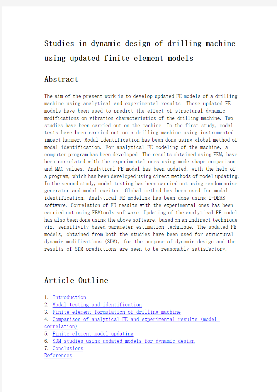
The aim of the present work is to develop updated FE models of a drilling machine using analytical and experimental results. These updated FE models have been used to predict the effect of structural dynamic modifications on vibration characteristics of the drilling machine. Two studies have been carried out on the machine. In the first study, modal tests have been carried out on a drilling machine using instrumented impact hammer. Modal identification has been done using global method of modal identification. For analytical FE modeling of the machine, a computer program has been developed. The results obtained using FEM, have been correlated with the experimental ones using mode shape comparison and MAC values. Analytical FE model has been updated, with the help of a program, which has been developed using direct methods of model updating. In the second study, modal testing has been carried out using random noise generator and modal exciter. Global method has been used for modal identification. Analytical FE modeling has been done using I-DEAS software. Correlation of FE results with the experimental ones has been carried out using FEMtools software. Updating of the analytical FE model has also been done using the above software, based on an indirect technique viz. sensitivity based parameter estimation technique. The updated FE models, obtained from both the studies have been used for structural dynamic modifications (SDM), for the purpose of dynamic design and the results of SDM predictions are seen to be reasonably satisfactory.
Article Outline
1. Introduction
2. Modal testing and identification
3. Finite element formulation of drilling machine
4. Comparison of analytical FE and experimental results (model correlation)
5. Finite element model updating
6. SDM studies using updated models for dynamic design
7. Conclusions
References
1. Introduction
Dynamic design aims at obtaining desired dynamic characteristics in machines and structures, which may include shifting of natural frequencies, desired mode shapes and vibratory response. The ultimate objectives are to have a quieter and more comfortable environment, higher reliability and better quality of product. The conventional dynamic design is basically hit and trial method in which we try to achieve desired dynamic characteristics by making several prototypes. The disadvantage of this technique is that actual design cycle takes a lot of time and therefore it is not cost effective. However, model updating based dynamic design saves design cycle time as well as reduces the cost involved. Various tools used for updating based dynamic design are: experimental modal analysis (EMA) including modal testing and modal identification, model updating and structural dynamic modification.
Ewins [1]and Maia and Silva [2]have explained the basic concepts of modal testing, which is an experimental approach to obtain mathematical model of a structure. In a modal test, the structure under test is excited either by an impact hammer or by a modal exciter, and the response of the structure is recorded at several experimental points, in the form of frequency response functions (FRFs), using a dual channel FFT analyzer. The experimental modal model gives information about the natural frequencies, corresponding mode shapes and modal damping factor and is useful for model updating. The model updating techniques helps us to bring analytical finite element models closer to real systems. In model updating an initial analytical FE model constructed for analyzing the dynamics of a structure is refined or updated using test data measured on actual structure such that the updated model describes the dynamic properties of the structure more correctly. The inaccuracies in FEM, when applied to dynamic problems are due to uncertainties in boundary conditions and structural damping etc.
Friswell and Mottershead [3] have discussed the finite element model updating in structural dynamics. Baruch and Bar-Itzhack and Baruch [4] and [5] considered analytical mass matrix to be exact and developed a direct method for updating using test data. Berman and Nagy [6]developed a method of model updating, which uses measured modes and natural frequencies to improve analytical mass and stiffness matrices. Structural dynamic modification (SDM) techniques [7]and [8]are the methods by which
dynamic behaviour of the structure is improved by predicting the modified behaviour brought about by adding modifications like those of lumped masses, rigid links, dampers etc. Thus the dynamic design using updated model is expected to be helpful in order to predict accurately and quickly, the effect of possible modifications on the dynamic characteristics of the structure at computer level itself, thus saving time and cost.
Sestieri [7]has discussed SDM application to machine tools and engines. Kundra [8]gave the method of structural dynamic modification via models. Modak [9] has discussed SDM predictions using updated FE model for an F-structure. He used constrained nonlinear optimization method for updating of a machine tool using stiffness parameters at the boundary [10]. The present paper deals with the FE model updating using direct as well as indirect method, and to use this updated FE model for dynamic design based on SDM predictions of a machine tool viz. a drilling machine. Two different studies are reported using different techniques for analytical and experimental analysis and for updating. Various objectives with which the present research work has been carried out are
? To develop updated FE models of a complex structure like that of a drilling machine and to use these updated models to predict the effect of various modifications on modal properties of the machine.
? To see whether hammer excitation yields good results for fairly complex structures like drilling machine or not, and to compare these results with those obtained from modal exciter.
? To analyze the results of SDM predictions obtained using the updated models derived in the studies.
2. Modal testing and identification
In the two studies mentioned earlier, different techniques have been used, for modal testing and identification. In the first study, impact hammer is used to excite the drilling machine structure, at various points as shown in Fig. 1 and Fig. 2. Response is taken at a fixed point with the help of an accelerometer.
(12K)
Fig. 1. Experimental setup (Study 1).
(4K)
Fig. 2. Hammer excitation locations.
In the present study, the drilling machine is excited at 30 locations and therefore, 30 FRFs are obtained. These FRFs are recorded in the form of inertance. The experimental FRFs, thus obtained are transferred to computer. Modal identification or modal parameter extraction consists of curve fitting a theoretical expression for an individual FRF to the actual measured data obtained. The experimental FRFs are analyzed by GRF-M method using modal analysis software ICATS [11] to obtain modal parameters of the drilling machine. In the second study, the machine tool structure has been excited at the base at point 28, referring to Fig. 2, using modal exciter and response has been measured at various points using piezoelectric accelerometers. The modal identification of the FRFs, thus measured has been carried out using global method GRF-M method in ICATS software.
Table 1compares the experimental natural frequencies obtained from both the methods, which shows minor differences in the two modal frequencies
Table 1.
Mode110.29 Hz8.67 HZ0.95311.20 Hz8.79 Hz0.946
Mode 265.14 Hz47.34 HZ0.90163.37 Hz44.40 Hz0.906
3. Finite element formulation of drilling machine
Several books have given the basic concepts of finite element analysis, some of them are: Zienkiewicz [12] and Bathe [13].
The drilling machine structure is very complicated with different mountings and accessories. Therefore exact modeling and analysis of the actual structure is difficult and it takes more computational effort. However for analytical FE analysis, simplified model of drilling machines has been considered. In study 1, the finite element modelling has been done using a program developed in MATLAB. Beam elements have been used for the analysis. The joints and boundary conditions are considered to be rigid and influence of structural damping on modal model parameters, is ignored. The relevant data used for the drilling machine is given below:
25 mm pillar type, height = 1.655 m, mass density = 7800 kg/m3, Young’s modulus= 200 Gpa, number of nodes = 30, number of elements = 29, number of nodes per element = 2, degrees of freedom per node = 3.
Fig. 3shows the structure of the drilling machine with the node numbers given for study 1.
(7K)
Fig. 3. Drilling machine structure for FE analysis.
The eigenvalues and eigenvectors have been calculated. The analytical FE model of the structure consists of 90 ×90-size mass and stiffness matrices (30 ×3, 30 nodes and 3 d.o.f. per node). But by experiment only 30 coordinates can be measured. Therefore FE model has been reduced using Guyan [14] reduction method with the help of a program developed in MATLAB.
In study 2, the finite element modelling has been done using I-DEAS software. The model has been made using beam mesh. Although the FE model has been simplified but the beam elements has rotational degree of freedom, which cannot be measured experimentally. Therefore the FE model needs to be reduced. The FE model has been reduced using model reduction utility
in FEMtools software. Fig. 4 and Fig. 5 shows the mode shape animation for the first and second mode respectively, using I-DEAS software.
(31K)
Fig. 4. Mode shape animation (first mode).
(23K)
Fig. 5. Mode shape animation (second mode).
4. Comparison of analytical FE and experimental results (model correlation)
The first stage of any reconciliation exercise is to determine how closely the experimental and analytical models correspond. If we are unable to obtain a satisfactory degree of correlation between the initial analytical FE model and the test data, then it is extremely unlikely that any form of model updating will succeed. Thus, a successful correlation is crucial for the success of model updating. Table 1gives the comparison between experimental and analytical natural frequencies. There are differences between analytical FE model predictions and experimental results. Thus the FE models need to be updated. However, the differences between the corresponding results of both studies are minor.
Apart from natural frequency comparison (as given in Table 1), another method of model correlation is mode shape comparison. To compare the mode shapes, we plot the deformed shapes of the structure for a particular mode, using experimental as well as analytical model. These mode shapes are plotted side-by-side for quick comparison. Mode shape corresponding to second mode is shown in Fig. 6, using ICATS software. It shows a fairly
good level of correlation between the experimental and analytical FE model.
(87K)
Fig. 6. Mode shape comparison.
Several researchers have developed techniques for quantifying the comparison between measured and predicted mode shapes. As an alternative to the graphical approach, Model Assurance Criterion i.e. MAC, [15]) is a widely used technique to estimate the degree of correlation between mode shape vectors. This provides a measure of the least squares deviation or ‘scatter’ of the points from the straight-line correlation. The MAC between a measured and analytical mode is:
(1)
where
m and
a
represents measured or experimental and analytical mode
shapes respectively. MAC is a scalar quantity whose value is between 0 and 1. A value of MAC close to 1 shows a good degree of correlation between experimental and analytical FE model. We can see in Table 1 that the MAC numbers are close to 1, though somewhat lower for the second mode. Table 1 also shows that the results obtained from both the studies are quite close to each other.
5. Finite element model updating
Model updating can be defined as “the process of correcting the numerical values of individual parameters in a analytical FE model using data obtained from an associated experimental model such that the updated model correctly describes the dynamic properties of the subject structure”.
Various model updating methods can be classified into two major groups: ? Direct matrix methods
? Indirect or iterative methods
Direct methods are capable of reproducing measured data exactly, but they provide no opportunity for the user to select parameters for updating. Here parameter means any physically realizable quantity like Young’s modulus, Poisson’s ratio, mass density etc. When using the direct methods, the entire stiffness and mass matrices are updated in a single
(non-iterative) solution step. Consequently any physical meaning, which the initial finite element model might have possessed, is lost in the updating process.
Techniques like the indirect methods, allow the updating parameters to be selected. So, considerable physical insight is required if the model is to be improved, not only in its ability to reproduce test results, but also in interpreting the parameters physically. Methods in this second group are iterative and, as such, considerably more expensive of computer effort.
Two studies have been carried out for model updating and computer programs for the same were developed in the present work using MATLAB. In the first study, two direct methods are applied to update the analytical FE model of the drilling machine structure.
Baruch and Bar-ltzhack [4] and Baruch [5] considered the mass matrix of the analytical model to be exact. The measured eigenvectors are corrected by using the relation:
(2)
The stiffness matrices of the analytical FE model after updating is given as:
K
=K a-K a T M a+M a T K a+M a T K a T M a+M aΛT M a(3)
u
Berman and Nagy [6] used a method similar to that of Baruch. They update mass and stiffness matrices while the mass matrix is updated to ensure the orthogonality of the exact FE model modes. The mass matrix is updated as:
(4)
(5) The stiffness matrix is updated using following equation:
(6
) The updated mass matrix obtained will be symmetric and stiffness matrix will be close to that of exact stiffness matrix. Results obtained from
Baruch and Berman–Nagy model updating methods are tabulated
in Table 2. It is clear from Table 2, that the updated model reproduces the measured frequencies. After updating, MAC values have been calculated again using Eq. It can be observed that updated MAC values show some improvement over the initial MAC values.
Table 2.
Comparison of experimental and updated FE frequencies and MAC values
Mod
e
num
ber
Study 1Study 2
Measured frequency Baruch method Berman method Measured
frequency
Sensitivity
method
Updated
frequency
MAC
Updated
frequency
MAC
Updated
frequency
MAC
Mod e 18.67 Hz8.67 Hz
0.9
25
8.67 Hz
0.9
34
8.79 Hz8.79 Hz
0.9
47
Mod e 247.34 Hz47.34 Hz
0.9
66
47.34 Hz
0.9
47
44.40 Hz44.43 Hz
0.9
13
The results after updating have been tabulated in Table 2. It clearly shows that after updating, the updated FE model closely represents the actual machine tool structure. It also shows that MAC values have also been improved after updating.
6. SDM studies using updated models for dynamic design
Structural dynamic modification (SDM) techniques are methods by which dynamic characteristics of the structure can be improved by adding the modifications like changing mass, spring, damping etc. The mass modification has been considered here for predicting dynamic characteristics using updated FE model.
A mass modification on drilling machine is introduced in the form of a lumped mass of 14.3 kg at the top of the vertical pillar, i.e. node 20 as in Fig. 3. The modal test for the mass modified machine is carried out by Modak [10], using impact hammer for excitation. The FRFs are analyzed in ICATS in order to obtain an experimental estimate of the altered dynamic characteristics of the drilling machine, as given in Table 3.
Table 3.
Comparison of measured and predicted frequencies, after mass modification, using updated FE model
Mode no.Measured
frequencies
SDM prediction using updated FE model
Baruch’s method Berman and Nagy’s method Sensitivity method
18.37 Hz8.34 Hz8.17 Hz8.40 Hz
246.05 Hz47.15 Hz46.96 Hz43.20 Hz
The effect of the same mass modification on the dynamic characteristics of the drilling machine has also been predicted by updated FE model. Table 3 gives a comparison of the predictions based on the updated FE models obtained by direct methods of Baruch, Berman and Nagy and by indirect
method based on sensitivity analysis, with that of the measured modified characteristics.
It is seen from the Table 3 that the updated FE model predictions of the natural frequencies are quite close to the measured value of natural frequencies. This shows the capability of the updated FE model to accurately predict the effect of structural modifications on the dynamic properties of the structure. Now, this updated FE model has been further used to predict, at computer level, the effect of various mass modifications on the structural dynamics of the drilling machine, for the purpose of dynamic design.
The mass modification can bring about significant changes in the natural frequencies of a structure. For predicting the effect of modifications using updated FE model, modification at node 20 and node 25, on the drilling machine has been considered. The effects on FRFs due to these modifications have been shown in Fig. 8and Fig. 9respectively. The values of the first two natural frequencies have been predicted using updated FE models and MODIFY module of ICATS software and are shown in Table 4
and Table 5.
(33K)
Fig. 8. Regenerated FRF due to mass modification at node 20.
(29K)
Fig. 9. Regenerated FRF due to mass modification at node 25.
Table 4.
Predicted natural frequencies after mass modification using 20 kg at node 20 (Panel
A), predicted natural frequencies after mass modification using 40 kg at node 20 (Panel
B)
Comparisons of SDM predictions using updated FE model
Baruch method Berman method Sensitivity method ICATS MODIFY Measured Frequencies Panel A
Mass modification of 20 kg
8.22 Hz7.99 Hz8.3 Hz8.2 Hz8.3 Hz
47.08 Hz46.83 Hz42.87 Hz47.1 Hz42.8 Hz
Panel B
Mass modification of 40 kg
7.83 Hz7.45 Hz7.76 Hz7.75 Hz7.8 Hz
46.86 Hz46.44 Hz41.27 Hz46.6 Hz41.3 Hz
Table 5.
Predicted natural frequencies after mass modification using 20 kg at node 25 (Panel
A), predicted natural frequencies after mass modification using 40 kg at node 25 (Panel
B)
Comparisons of SDM predictions using updated FE model
Baruch method Berman method Sensitivity method ICATS MODIFY Measured frequencies
Panel A
Mass modification of 20kg
8.34 Hz8.44 Hz8.41 Hz8.35 Hz8.4 Hz 42.24 Hz43.74 Hz41.67 Hz42.2 Hz41.6 Hz
Comparisons of SDM predictions using updated FE model
Baruch method Berman method Sensitivity method ICATS MODIFY Measured frequencies
Panel B
Mass modification of 40kg
8.03 Hz8.21 Hz8.04 Hz8.1 Hz8.1 Hz
38.89 Hz41.02 Hz39.67 Hz39.15 Hz39.5 Hz
7. Conclusions
Comparison of results obtained from experimental modal analysis and FE models of a drilling machine, indicate that its finite element models need to be updated. This is necessary in order to predict dynamic behavior of the complex structure with an acceptable accuracy.
An experimentation involving modal testing has been carried out on the drilling machine using impact hammer as well as modal exciter. It has been observed that both impact hammer and modal exciter yield good results for fairly complex structures like drilling machine.
Analytical FE model has been updated in the light of experimental data using direct as well as indirect methods. Both the methods give results, which are fairly close when used for predicting results of SDM attaching additional mass on the machine at different locations. The predicted results have been validated by comparison with measured results and are seen to be fairly accurate in particular for the indirect method using sensitivity analysis.
References
[1]D.J. Ewins, Modal Testing: Theory and Practice, John Willey and Sons, New York (2000).
[2] N.M.M. Maia and J.M.M. Silva, Theoretical and Experimental Modal Analysis, John Willey and Sons, New York (1997).
[3]M.I. Friswell and J.E. Mottershead, Finite Element Model Updating in Structural Dynamics, Kluwer Academic Publishers, Dordrecht (1995).
[4] M. Baruch and I.Y. Bar-ltzhack, Optimal weighted orthogonalization of measured modes, AIAA Journal16 (1978), pp. 346–351.
[5] M. Baruch, Optimisation procedure to correct stiffness and flexibility matrices using vibration test data, AIAA Journal16 (1978), pp. 1208–1210.
[6]A. Berman and E.J. Nagy, Improvement of a large analytical model using test data, AIAA Journal21 (1983), pp. 1168–1173.
[7] A. Sestieri, SDM application to machine tools and engines, Sadhana 25 (2000), pp. 305–317.
[8] T.K. Kundra, Structural dynamic modification via model, Sadhana25 (2000), pp. 261–276.
[9]S.V. Modak, Studies in Finite Element Model Updating and Application to Dynamic Design, Ph.D. Thesis, Department of Mechanical Engineering, IIT Delhi, 2001.
[10]S.V. Modak, T.K. Kundra, B.C. Nakra, Dynamic design of machine tool structures using an updated model Pro. IMAC- XX, 2002, pp. 1489–1494.
[11] ICATS Reference Manual, Imperial College, London, 1996.
[12]O.C. Zienkiewicz, The Finite Element Method in Engineering Science, McGraw-Hill Publishing Company, London (1977).
[13] K.J. Bathe and E.J. Wilson, Numerical Methods in Finite Element Analysis, Prentice-Hall, Englewood Cliffs, NJ (1982).
[14] R.J. Guyan, Reduction of stiffness and mass matrices, AIAA Journal 3 (1965), p. 380.
[15]R.L. Allemang, BD.L. Rown. A correlation coefficient for modal vector analysis, Proc. 1st IMAC, 1982, pp. 110–116.
[16] FEMtools Manual Version 2.0, Dynamic design solutions, 2000.
Corresponding author. Steam Turbine Engineering, TCGT Division, Bharat Heavy Electricals Limited, Hyderabad-502032, India
译文
利用有限元模型对钻机进行动态分析的研究
摘要
现在的工作的目的是使用分析和实验的结果发展和改进钻机的有限元分析模型,这种有限元分析已经用在监测将钻机的工作特性修改后对钻机动态的结构的影响;对钻机将有两个研究就进行。第一个研究是:使用工具对钻机进行冲击来观察这种冲击对钻机的影响的实验已经在进行,通过人们公认对模型的证明我门已经知道这种方法的可行性;为了这一个有限元模型分析的机器,一个计算机程序已经被设计出来。有限元分析获得的结果是将通过实验得到模型的比较与测量和控制的价值联系起来。有限元分析模型已经被改进,是由于一个已经使用的有限元分析模型程序的改进。第二个研究是:模式上的测试已经完成,这种测试包括运用各种任意的声音和模式的刺激。公认的模式的测试方法被用来作为这种有限元分析模型的证据。利用I-DEAS软件已经对有限元分析模型的作了分析。利用FEMtools软件已经对有限元分析模型和实验得到的结果的联系进行了分析,利用以上两种软件已经对有限元分析模型进行了间接的改进。灵敏度基于对参数估量的技术。通过以上两种研究,对这种分析模型进行结构和动态的修改。我们对动态设计的结果和结构和动态的修改相当的满意。
目录
1.绪论;
2.模型的测试和结论;
3.钻机的有限元分析元素的表达;
4.有限元分析的结果和实验结果的比较;
5.有限元分析的发展;
6.利用有限元分析对动态设计的动态和结构的修正;
7.结论。
参考文献
1.绪论
动态设计的目的在于获得想要的机器和构件的动态参数,这些动态参数包括震荡频率,想要得到的结构尺寸和震荡响应,而根本的目的是有一个安静和舒适的环境,高的可靠性和更好的产品质量。常规的动态设计是通过很多的原形的分析和实验来获得自己想要的参数。这个设计的缺点是:要进行这个实验和分析需要很多的时间和精力,所以根本就没有效率所言。然而,新型的有限元分析节省了时间节省了有关的花费。
动态设计所用的各种方法是:实验的模型分析(形态测试和实验确认),模型改进和结构上的,形态上的修改。EWINS,MAIN和SILVA对模型测试进行了基本概念的解释。模型测试是通过实验的方法获得机构的数学模型。在这个实验中,构件用一个锤子进行打击或用刺激物进行刺激,是它发生变形,在这个过程中,构件的变形已经被仪器所记录。然后,用一个接口将这种变形的信号传递的分析
器里面,以构件的响应函数的形式进行分析。这种实验模型提给给我们一个正常的频率相应的外形和模型的制动因数是非常有用的对模型的改进来说。改进后的有限元分析技术帮助我们使得分析有限元要素模型接近于真实的系统。在模型更新起初,有限元模型分析因为结构的动力学,模型构造是精确或者最新的。用标准的,最新的测试数据的使用,以至于对机构模型的描述是非常准确的。当将有限元分析应用于不准确的边界条件和结构减震时,将会出现错误。
Friswen 和Mottershead 在结构动力学中讨论有限元模型分析的发展;在Baruch和Bar-Itzhach中考虑分析的大众点阵式是精确的而且在后来通过最新的实验数据对发展为一种直接的数学方法;Berman和Nijy发明了一种改进模型的方法。这种方法使用标准的dos命令和正常的频率来提高对大多数和坚硬金属分析的精确。结构的动态休整技术是一种方法,通过增加改进参数(刚性连接,节气阀等)。因而,利用最新的模型来准确的和快速的预测动态设计是非常有用的,在动态设计时,计算机利用自身程序对模型进行结构动态特性的有可能修正,这样即节省时间又节省花费,Sestieri讨论将结构动态修正运用到工作母机和发动机上Kundra提供了一种结构动态的修正方法。Modak讨论通过最新的有限元模型分析对构件动态修正的预测,在边界条件,利用硬度参数时对最新的机床,它常常不是非线性最优化的方法。
这篇论文要处理最新的有限元模型分析通过使用指导方法和间接方法来解决动态设计构件动态参数的修正与预测。
一个钻机,两重不同的设计方法被报道使用不同的技术方法来分析和解决最新的动态分析设计。
现在多种研究工作被实施的目的是:
(1)来发现一种最新的有限元分析系统来解决象钻机一样复杂结构的设计和使用这种有限元分析模型来预测各种参数在机器模具上的
响应。
(2)让这种变形的模型和正常的模型相比较来看象钻机一样复杂结构对其进行冲击时产生变形是否有好的方面出现。
(3)利用这种最新研究的模型分析方法来分析获得机构动态修正参数的测试结果。
2.模型的测试和结论;
在二项研究被提及更加早期,对模型的测试和结论,人们引用了不同的技术。在第一个实验中,用冲击的方法使钻机的构件发生变形,其数值的变化如图1
和图2:
(12K)
图1实验进行前
(4K)
图2实验后
变形是在过载器件的帮助下对一个固定点的取样;在现在的研究中,使用仪器使得在钻机的30个部位进行刺激使之发生变形,则这样就能获得30个响应函数。这些响应函数在变化以前就已经被记录下来。同时就这些获得响应函数输送到计算机里面,将获得的数据以曲线的形式表达出来,再将其进行分析就能获得标准的,最新的钻机的参数数据。
第二个实验是:使机械机构地部的28个点发生变形并用压电式加速仪进行测量,通过ICATS软件对频率响应函数的正确性进行了证明,结果显示这种方法得到的数据是准确的。表1是通过两种不同的方法得到的频率的数据,从数据来看,它们是完全不一样的:
表1
方式110.29 Hz8.67 HZ0.95311.20 Hz8.79 Hz0.946
方式265.14 Hz47.34 HZ0.90163.37 Hz44.40 Hz0.906
3.钻机的有限元分析元素的表达;
像Zienkiewicz 和 Bathe一样,人们对有限元分析的一些概念进行了定义。与其他的机器和构件相比,钻机的构件是非常复杂的;因此,对实际的构件分析是很难的,而且会花费大量的时间和精力。然而,对有限元模型分析来说,钻机的简单化的模型被使用。在实验1中,有限元分析模型被MATLAB作成一个计算机程序;光线元素已经被应用到分析当中,刚性连接和边界条件被认为对结构减震是有影响的在模型参量上,但是,人们往往将其忽略。
钻机的相关使用数据如下:
25毫米的柱子模型;高度= 1.655 m;质量密度= 7800 kg/m3;杨氏系数= 200 Gpa;连节点的个数= 30;设计元素的个数= 29;每个元素的节点个书= 2;每个节点的自由度= 3。
图3表示了实验1中钻机结构的节点数:
(7K)
图3钻机结构的有限元分析
现在,钻机的特征值和特征向量已经被计算出来。结构的有限元分析的数据包括90 ×90-的外行参数和材料硬度(30 ×3,30个节点,每个节点的自由度= 3)。但是,实验只有30个坐标可以测量,有限元模型分析在MATLAB设计的一个程序下得到了简化。
在实验2中,通过使用I-DEAS软件将有限元分析模型制作出来,模型是用射线滤网制作的。虽然有限元分析模型是单一化的但是射线元素有旋转的自由度,使得无法实验性地被测量。因此,有限元分析模型需要进一步的简化。在以后的发展过程中,通过使用FEM软件有限元分析模型得到进一步简化。图4和图5显示了在使用I-DEAS软件以后实验1和实验2的结构形式:
(31K)
图4.实验1的结构形式
(23K)
图5.实验二的结构形式
4. 有限元分析的结果和实验结果的比较;
第一阶段的调试的准确程度将直接影响有限元分析模型与实验的模型的接近程度,如果,我们不能使实验得到的数据和有限元分析得到的模型相吻合,那么,这种取得成功的方法是不可靠的;因此,得到的数据和有限元分析得到的模型相吻合是至关重要的。表1提供给我们:实验的频率和分析得到的频率的区别,这儿存在很大的不同对于有限元分析得到的结果和实验得到的结果。因而,有限元模型分析需要进行改进。
除了与正常的频率做比较的到结论之外,还有一种方法是:将要分析的模型与其相近的模型作比较从而得到想要的结果。具体的方法是:做模型的外型比较;我们将不规整的模型分割成一些特殊的模型,以便与实验和分析得到的结果做比较。将模型分割成一块一块的相同摸小模型,这样就可以做快速对比。通过使用ICATS这种软件,是模型之间可以相似到图6所示的情形;图6显示给我们清晰的,
准确的实验分析与有限元分析之间的联系。
(87K)
图6
一些科学家发明了一种定量的进行标准的和预测的模型的比较方法。作为一种图形示的方法,它将成为保证模型质量依据。测试与控制是评估两种方法模型相近程度的广泛使用的方法,它给我们提供了模型的尺寸上下直线的偏差。关于标准模型和分析的模型之间有如下的公式:
式中
m 和
a
是标准的或实验分析模型各自的外型尺寸。
测试与控制的价值可以用0和1来表示:1就表示实验和分析模型的尺寸接近与标准模型的尺寸;则0就有相反的结果。从表1中我们可以发现经有限元分析得到的尺寸虽然与模型2比较数值有一点小但还是接近与数字1的;从表中还可以发现两个实验的数据是很接近的。
5. 有限元分析的发展趋势
在有限元分析中使用从相关实验模型中得到的数据改正个别参数的含义的程序描述了服从结构的动态变化。
各种改进的模型分析的方法可以被分为两类:
①直接点阵法;
②间接或反复法。
直接的方法可以精确的计算出标准的数据,但是,对使用者来说没有机会来改进所涉及到的参数。在这儿参数就以为着像杨氏模数,泊松比,质量密度等这样的物理量,当使用直接方法的时候,所有的硬度参数和部分的点阵被更新在一个专门的参数设计阶段。因此,一些物理方法只注重于更新过程,而往往忽略结果使得这种最后被否定。
科学的技术(间接的方法)容许选择性的使用标准的参数。如果模型要被改进的话,那么敏锐的观察力是必须的。通过它不但可以获得结果,而且还能解释一些参数的含义。另外,我们还要在计算机上花费大多数的时间反复的进行计算与演算。
两种科学方法通过改进的模型已经被使用,同时,计算机程序通过MATLAB也别应用到设计当中。在第一个实验中,两种直接方法被应用于改进钻机机构有限元分析模型。
Baruch ,Bar-ltzhack和Baruch认为模型点阵分析法是准确的,而且,通过下面的公式修正了标准的参数;
有限元分析模型的力矩系数通过下式也被更新;
K u=K a-K a T M a+M a T K a+M a T K a T M a+M aΛT M a
中英文文献翻译
毕业设计(论文)外文参考文献及译文 英文题目Component-based Safety Computer of Railway Signal Interlocking System 中文题目模块化安全铁路信号计算机联锁系统 学院自动化与电气工程学院 专业自动控制 姓名葛彦宁 学号 200808746 指导教师贺清 2012年5月30日
Component-based Safety Computer of Railway Signal Interlocking System 1 Introduction Signal Interlocking System is the critical equipment which can guarantee traffic safety and enhance operational efficiency in railway transportation. For a long time, the core control computer adopts in interlocking system is the special customized high-grade safety computer, for example, the SIMIS of Siemens, the EI32 of Nippon Signal, and so on. Along with the rapid development of electronic technology, the customized safety computer is facing severe challenges, for instance, the high development costs, poor usability, weak expansibility and slow technology update. To overcome the flaws of the high-grade special customized computer, the U.S. Department of Defense has put forward the concept:we should adopt commercial standards to replace military norms and standards for meeting consumers’demand [1]. In the meantime, there are several explorations and practices about adopting open system architecture in avionics. The United Stated and Europe have do much research about utilizing cost-effective fault-tolerant computer to replace the dedicated computer in aerospace and other safety-critical fields. In recent years, it is gradually becoming a new trend that the utilization of standardized components in aerospace, industry, transportation and other safety-critical fields. 2 Railways signal interlocking system 2.1 Functions of signal interlocking system The basic function of signal interlocking system is to protect train safety by controlling signal equipments, such as switch points, signals and track units in a station, and it handles routes via a certain interlocking regulation. Since the birth of the railway transportation, signal interlocking system has gone through manual signal, mechanical signal, relay-based interlocking, and the modern computer-based Interlocking System. 2.2 Architecture of signal interlocking system Generally, the Interlocking System has a hierarchical structure. According to the function of equipments, the system can be divided to the function of equipments; the system
文献翻译英文原文
https://www.360docs.net/doc/6212301441.html,/finance/company/consumer.html Consumer finance company The consumer finance division of the SG group of France has become highly active within India. They plan to offer finance for vehicles and two-wheelers to consumers, aiming to provide close to Rs. 400 billion in India in the next few years of its operations. The SG group is also dealing in stock broking, asset management, investment banking, private banking, information technology and business processing. SG group has ventured into the rapidly growing consumer credit market in India, and have plans to construct a headquarters at Kolkata. The AIG Group has been approved by the RBI to set up a non-banking finance company (NBFC). AIG seeks to introduce its consumer finance and asset management businesses in India. AIG Capital India plans to emphasize credit cards, mortgage financing, consumer durable financing and personal loans. Leading Indian and international concerns like the HSBC, Deutsche Bank, Goldman Sachs, Barclays and HDFC Bank are also waiting to be approved by the Reserve Bank of India to initiate similar operations. AIG is presently involved in insurance and financial services in more than one hundred countries. The affiliates of the AIG Group also provide retirement and asset management services all over the world. Many international companies have been looking at NBFC business because of the growing consumer finance market. Unlike foreign banks, there are no strictures on branch openings for the NBFCs. GE Consumer Finance is a section of General Electric. It is responsible for looking after the retail finance operations. GE Consumer Finance also governs the GE Capital Asia. Outside the United States, GE Consumer Finance performs its operations under the GE Money brand. GE Consumer Finance currently offers financial services in more than fifty countries. The company deals in credit cards, personal finance, mortgages and automobile solutions. It has a client base of more than 118 million customers throughout the world
J2EE开发框架外文翻译文献
中英文资料外文翻译文献 J2EE开发框架 Java2企业版为中间件领域思想的统一上发挥了很大的作用。比如,J2EE为分布式事务管理、目录服务和消息服务提供了一套标准的编程接口。J2EE的基础——Java2标准版(J2SE) ,成功地为Java提供了一套访问关系数据库的标准。 但是,就像本文中“J2EE缺乏对编程的支持”提到的一样,J2EE这个平台没有能够提供一个令人满意的应用程序编程模型。Sun公司和一些大的应用服务器供应商都想用开发工具来降低J2EE开发的复杂性,但是这些工具没有其他的JA V A 开发工具优秀,后者有先进的重构工具,和.NET平台相比,J2EE的工具支持显得很逊色。 很多J2EE开发工具自动产生的代码像这些工具本身同样复杂。在开源社区很多小型J2EE开发者选择了另外一种开发方式——一些可以降低J2EE开发难度的开发框架,较为流行的比如:Struts, Hibernate, 和Spring Framework,他们当今很多J2EE项目种扮演着重要角色。 为什么要采用框架? 框架是一由一些类组成,正式这些类为应用程序提供了一个可重用的设计――或者我们经常提到的——应用程序种的一层。应用程序代码访问类库从而执行任务,而框架是调用应用程序代码,从而管理程序的流程。这就是经常说道的好莱坞原则:“不要试图联系我们,我们到时候自会通知你。”开发者写的程序在运行时由框架调用。 设计一个在各种未知背景下都可以使用的框架是很有挑战性的。框架很适合在复杂的J2EE开发中使用,它可以为开发者提供一个简单易用的模型。采用一个经过良好设计的开源框架有很多好处:
1、在好的框架下,开发者只需要写一些必须的代码;他们不需要直接接触底层的API。这一点很重要。 2、经过良好设计的框架可以为程序提供清晰的结构并且提高程序的内聚性。好清晰的结构使得其他人可以更容易加入项目。 3、一个容易使用的框架可以通过一些例子和文档为用户提供最佳实践。 4、采用成功的框架的代码比自己的代码容易测试 5、框架只有提供了一些值得使用的功能才会变得流行。J2EE工程只有真正需要框架的时候才会用它,而自己的框架并不是这样,后者是处于统治地位的。 J2EE本身也提供了一些框架。比如,Enterprise Java-Beans (EJB) container 或者Servlet engine,二者都运用了“ 采用了好莱坞原则”这个思想,并采用运行时调用来管理对象。像Struts这些开源web应用框架正式建立在这两个框架的基础上的,本文讨论的重点也是像Struts这样建立在J2EE上的框架,他们为开发者提供了更为简单的模型,和其他的一些好处。 开源框架的出现 很多大型的J2EE项目都用自己的内部框架来隐藏平台的复杂性,直到最近人们才逐渐发现一些在很多项目中都存在的共有的难题,这些难题都可以由一个较为统一的解决方案来解决。而有的框架正好可以充当这些问题的解决方案。现在有种很明显的趋势:与从前的内部框架相比,这些框架将成为这些难题的更加“标准化”的解决方案。 J2EE平台的日益成熟是这些框架流行的一个原因。开发者知道有些地方是J2EE的标准API无能为力的,倚他们的经验来看,要弥补这个缺陷是很困难的。于此同时,一些优秀的开源框架可供使用,它们提供了极为丰富的技术文档,在它们背后还有一个专业的团队做支持,并且一切都是免费的。 Struts 在web应用程序产生的那时就有了开源框架。在1999-2000年,开发者们意识到JSP“Model1”的缺陷,JSP中充斥着请求处理代码和静态数据模板,这意味着你不得不把业务逻辑和复杂的HTML以及其他的标签混到一起。那个时候
英文文献翻译
中等分辨率制备分离的 快速色谱技术 W. Clark Still,* Michael K a h n , and Abhijit Mitra Departm(7nt o/ Chemistry, Columbia Uniuersity,1Veu York, Neu; York 10027 ReceiLied January 26, 1978 我们希望找到一种简单的吸附色谱技术用于有机化合物的常规净化。这种技术是适于传统的有机物大规模制备分离,该技术需使用长柱色谱法。尽管这种技术得到的效果非常好,但是其需要消耗大量的时间,并且由于频带拖尾经常出现低复原率。当分离的样本剂量大于1或者2g时,这些问题显得更加突出。近年来,几种制备系统已经进行了改进,能将分离时间减少到1-3h,并允许各成分的分辨率ΔR f≥(使用薄层色谱分析进行分析)。在这些方法中,在我们的实验室中,媒介压力色谱法1和短柱色谱法2是最成功的。最近,我们发现一种可以将分离速度大幅度提升的技术,可用于反应产物的常规提纯,我们将这种技术称为急骤色谱法。虽然这种技术的分辨率只是中等(ΔR f≥),而且构建这个系统花费非常低,并且能在10-15min内分离重量在的样本。4 急骤色谱法是以空气压力驱动的混合介质压力以及短柱色谱法为基础,专门针对快速分离,介质压力以及短柱色谱已经进行了优化。优化实验是在一组标准条件5下进行的,优化实验使用苯甲醇作为样本,放在一个20mm*5in.的硅胶柱60内,使用Tracor 970紫外检测器监测圆柱的输出。分辨率通过持续时间(r)和峰宽(w,w/2)的比率进行测定的(Figure 1),结果如图2-4所示,图2-4分别放映分辨率随着硅胶颗粒大小、洗脱液流速和样本大小的变化。
基于有限元分析的发动机缸体压铸模具设计【毕业论文(含任务书、外文翻译)】
BI YE SHE JI (20 届) 基于有限元分析的发动机缸体压铸模具设计 所在学院 专业班级材料成型与控制工程 学生姓名学号 指导教师职称 完成日期年月
任务下达日期:2016年3月1日 毕业设计日期:2016年3月1日至2016年6月12日 毕业设计题目:基于有限元分析的发动机缸体压铸模具设计 毕业设计主要内容和要求: 内容: 1、查阅30篇中文文献及10篇左右的英文文献,充分了解设计内容。 2、利用NX10.0建立缸体三维模型,使用Anycasting完成缸体压铸过程模拟分析。 3、参考设计手册和模拟结果完成压铸模具设计,并绘制模具工程图。 4、要求翻译一篇近三年的英文文献,汉字内容应不少于3000字。 要求: 1、努力学习、勤于实践、勇于创新,保质保量地完成毕业设计任务。 2、遵守纪律,保证出勤。因事、因病离岗,应事先向指导老师请假。否则作为缺席处理。 3、独立完成规定的工作内容。不弄虚作假,不抄袭和拷贝别人的工作内容。 4、毕业设计必须符合中国矿业大学毕业论文规范化规定,否则不得参加毕业答辩。 院长签字:指导教师签字:
本文以某汽车的发动机铝合金缸体压铸件为研究对象,对该缸体压铸件可能铸造缺陷进行分析及预测。首先利用NX10.0设计该缸体的三维模型,并参照设计手册完成浇注系统和排溢系统的设计。然后利用铸造模拟软件anycasting v4.0对压铸模具型腔、浇注系统和排溢系统整体进行充填和凝固过程进行模拟研究。分析目前的工艺和设计的浇注系统、排溢系统的是否存在问题,对重要的压铸工艺参数进行优化,并优化压铸模具浇注系统和排溢系统。根据以上模拟结果和设计手册,利用NX10.0、AUTOCAD完成其余结构的设计。使用anycasting v4.0主要完成充型分析,充型过程热分析和热凝固分析,其中重要的工艺参数是冲头快压射速度、浇注温度、冲头高低速转换点和模具预热温度,最后得到一个缺陷比较少的模拟结果。对一般充型缺陷,可以通过优化设计浇注系统、排气系统改进,对凝固缺陷可以通过修改冷却系统的位置进行改进。模具设计部分包括模具型芯部分设计、模架设计、侧抽芯系统设计、顶出系统设计、模具厚度核算、动模座板行程校核、最小合模距离与最大开模距离校核和模具最大外形轮廓校核。最后依据模拟分析结果和模具结构设计,利用NX10.0三维造型软件完成缸体铸件的压铸模具设计。 关键词:铝合金缸体、数值模拟、压铸、模具设计
外文文献翻译——参考格式
广东工业大学华立学院 本科毕业设计(论文) 外文参考文献译文及原文 系部经济学部 专业经济学 年级 2007级 班级名称 07经济学6班 学号 16020706001 学生姓名张瑜琴 指导教师陈锶 2011 年05月
目录 1挑战:小额贷款中的进入和商业银行的长期承诺 (1) 2什么商业银行带给小额贷款和什么把他们留在外 (2) 3 商业银行的四个模型进入小额贷款之内 (4) 3.1内在的单位 (4) 3.2财务子公司 (5) 3.3策略的同盟 (5) 3.4服务公司模型 (6) 4 合法的形式和操作的结构比较 (8) 5 服务的个案研究公司模型:厄瓜多尔和Haiti5 (9)
1 挑战:小额贷款中的进入和商业银行的长期承诺 商业银行已经是逐渐重要的运动员在拉丁美洲中的小额贷款服务的发展2到小额贷款市场是小额贷款的好消息客户因为银行能提供他们一完整类型的财务的服务,包括信用,储蓄和以费用为基础的服务。整体而言,它也对小额贷款重要,因为与他们广泛的身体、财务的和人类。如果商业银行变成重的运动员在小额贷款,他们能提供非常强烈的竞争到传统的小额贷款机构。资源,银行能廉宜地发射而且扩张小额贷款服务rela tively。如果商业广告银行在小额贷款中成为严重的运动员,他们能提出非常强烈的竞争给传统的小额贷款机构。然而,小额贷款社区里面有知觉哪一商业银行进入进入小额贷款将会是短命或浅的。举例来说,有知觉哪一商业银行首先可能不搬进小额贷款因为时候建立小额贷款操作到一个有利润的水平超过银行的标准投资时间地平线。或,在进入小额贷款,银行之后可能移动在-上面藉由增加贷款数量销售取利润最大值-或者更坏的事,退出如果他们是不满意与小额贷款的收益性的水平。这些知觉已经被特性加燃料商业银行的情形进入小额贷款和后来的出口之内。在最极端的,一些开业者已经甚至宣布,”降低尺度死!”而且抛弃了与主意合作的商业银行。 在最 signific 看得到的地方,蚂蚁利益商业银行可能带给小额贷款,国际的ACCION 发展发射而且扩张的和一些商业银行的关系小额贷款操作。在这些情形的大部分方面, ACCION 和它的合伙人正在使用方法,已知的当做服务公司模型,表演早答应当做一个能工作的方法克服真正的。 商业银行的障碍进入和穿越建立长命的小额贷款操作一个商业银行 这论文描述如何服务公司模型、住址商业银行中的主要议题进入进小额贷款,监定成功建立的因素动作井小额贷款服务公司,和礼物结果和小额贷款的课servic e 公司用最长的经验,在海地和审判官席 del 的 SOGEBANK│ SOGESOL 初期结果指出那这服务公司模型表现一重要的突破在促成商业银行进入和留在小额贷款。在厄瓜多尔的 Pichincha│ CREDIFE。初期结果指出服务公司模型在促成商业广告中表现一次重要的突破银行进入而且留在小额贷款。
外文文献及翻译
文献翻译 原文 Combining JSP and Servlets The technology of JSP and Servlet is the most important technology which use Java technology to exploit request of server, and it is also the standard which exploit business application .Java developers prefer to use it for a variety of reasons, one of which is already familiar with the Java language for the development of this technology are easy to learn Java to the other is "a preparation, run everywhere" to bring the concept of Web applications, To achieve a "one-prepared everywhere realized." And more importantly, if followed some of the principles of good design, it can be said of separating and content to create high-quality, reusable, easy to maintain and modify the application. For example, if the document in HTML embedded Java code too much (script), will lead the developed application is extremely complex, difficult to read, it is not easy reuse, but also for future maintenance and modification will also cause difficulties. In fact, CSDN the JSP / Servlet forum, can often see some questions, the code is very long, can logic is not very clear, a large number of HTML and Java code mixed together. This is the random development of the defects. Early dynamic pages mainly CGI (Common Gateway Interface, public Gateway Interface) technology, you can use different languages of the CGI programs, such as VB, C / C + + or Delphi, and so on. Though the technology of CGI is developed and powerful, because of difficulties in programming, and low efficiency, modify complex shortcomings, it is gradually being replaced by the trend. Of all the new technology, JSP / Servlet with more efficient and easy to program, more powerful, more secure and has a good portability, they have been many people believe that the future is the most dynamic site of the future development of technology. Similar to CGI, Servlet support request / response model. When a customer submit a request to the server, the server presented the request Servlet, Servlet responsible for handling requests and generate a response, and then gave the server, and then from the server sent to
英文文献及中文翻译
毕业设计说明书 英文文献及中文翻译 学院:专 2011年6月 电子与计算机科学技术软件工程
https://www.360docs.net/doc/6212301441.html, Overview https://www.360docs.net/doc/6212301441.html, is a unified Web development model that includes the services necessary for you to build enterprise-class Web applications with a minimum of https://www.360docs.net/doc/6212301441.html, is part of https://www.360docs.net/doc/6212301441.html, Framework,and when coding https://www.360docs.net/doc/6212301441.html, applications you have access to classes in https://www.360docs.net/doc/6212301441.html, Framework.You can code your applications in any language compatible with the common language runtime(CLR), including Microsoft Visual Basic and C#.These languages enable you to develop https://www.360docs.net/doc/6212301441.html, applications that benefit from the common language runtime,type safety, inheritance,and so on. If you want to try https://www.360docs.net/doc/6212301441.html,,you can install Visual Web Developer Express using the Microsoft Web Platform Installer,which is a free tool that makes it simple to download,install,and service components of the Microsoft Web Platform.These components include Visual Web Developer Express,Internet Information Services (IIS),SQL Server Express,and https://www.360docs.net/doc/6212301441.html, Framework.All of these are tools that you use to create https://www.360docs.net/doc/6212301441.html, Web applications.You can also use the Microsoft Web Platform Installer to install open-source https://www.360docs.net/doc/6212301441.html, and PHP Web applications. Visual Web Developer Visual Web Developer is a full-featured development environment for creating https://www.360docs.net/doc/6212301441.html, Web applications.Visual Web Developer provides an ideal environment in which to build Web sites and then publish them to a hosting https://www.360docs.net/doc/6212301441.html,ing the development tools in Visual Web Developer,you can develop https://www.360docs.net/doc/6212301441.html, Web pages on your own computer.Visual Web Developer includes a local Web server that provides all the features you need to test and debug https://www.360docs.net/doc/6212301441.html, Web pages,without requiring Internet Information Services(IIS)to be installed. Visual Web Developer provides an ideal environment in which to build Web sites and then publish them to a hosting https://www.360docs.net/doc/6212301441.html,ing the development tools in Visual Web Developer,you can develop https://www.360docs.net/doc/6212301441.html, Web pages on your own computer.
仪表板外文文献翻译、中英文翻译、外文翻译
Dashboard From Wikipedia, the free encyclopedia This article is about a control panel placed in the front of the car. For other uses, see Dashboard (disambiguation). The dashboard of a Bentley Continental GTC car A dashboard (also called dash, instrument panel (IP), or fascia) is a control panel located directly ahead of a vehicle's driver, displaying instrumentation and controls for the vehicle's operation. Contents 1.Etymology 2.Dashboard features 3.Padding and safety 4.Fashion in instrumentation 5.See also 6.References Etymology Horse-drawn carriage dashboard Originally, the word dashboard applied to a barrier of wood or leather fixed at the front of a horse-drawn carriage or sleigh to protect the driver from mud or other debris "dashed up" (thrown up) by the horses' hooves.[1] Commonly these boards did not perform any additional function other than providing a convenient handhold for ascending into the driver's seat, or a small clip with which to secure the reins when not in use. When the first "horseless carriages" were constructed in the late 19th century, with engines mounted beneath the driver such as the Daimler Stahlradwagen, the simple dashboard was retained to protect occupants from debris thrown up by the cars' front wheels. However, as car design evolved to position the motor in front of the driver, the dashboard became a panel that protected vehicle occupants from the heat and oil of the engine. With gradually increasing mechanical complexity, this panel formed a convenient location for the placement of gauges and minor controls, and from this evolved the modern instrument panel,
有限元分析系统的发展现状与展望外文翻译
Finite element analysis system development present situation and forecast Along with modern science and technology development, the people unceasingly are making the faster transportation vehicle, the large-scale building, the greater span bridge, the high efficiency power set and the preciser mechanical device. All these request engineer to be able precisely to forecast in the design stage the product and the project technical performance, needs to be static, technical parameter and so on dynamic strength to the structure as well as temperature field, flow field, electromagnetic field and transfusion carries on the analysis computation. For example analysis computation high-rise construction and great span bridge when earthquake receives the influence, has a look whether can have the destructive accident; The analysis calculates the nuclear reactor the temperature field, the determination heat transfer and the cooling system are whether reasonable; Analyzes in the new leaf blade the hydrodynamics parameter, enhances its operating efficiency. The sell may sum up as the solution physics question control partial differential equations often is not impossible. In recent years the finite element analysis which develops in the computer technology and under the numerical analysis method support(FEA, Finite Element Analysis) the side principle for solves these complex project analysis estimation problems to provide the effective way. Our country in " 95 " Plan period vigorously promotes the CAD technology, mechanical profession large and middle scalene terries CAD popular rate from " 85 " End 20% enhances that present 70%.With enterprise application of CAD, engineering and technical personnel has gradually get rid drawing board, and will join the main energy how to optimize the design, engineering and improving the quality of products, computer-aided engineering analysis (CAE. Computer Aided Engineering) method and software will be the key technical elements . ln engineering practice, finite element analysis software and CAD system integration design standards should be a qualitative leap, mainly in the following aspects : The increase design function, reduces the design cost; Reduces design and the analysis cycle period; Increase product and project reliability; Uses the optimized design, reduces the material the consumption or the cost;
计算机 JSP web 外文翻译 外文文献
外文资料 所译外文资料: ①作者:Dan Malks ②书名:Professional JSP ③出版时间: 2000.7.26 ④所译章节: Chapter 12 12.1Introductory Good Web application design tries to separate business objects, presentation, and manipulation of the objects into distinct layers. One benefit of using JavaServer Pages technology is that it allows us to separate the role of a Web designer more clearly from that of a software developer. While on a small-scale project, one individual may occupy both roles, on a larger project, they are likely to be separate and it is beneficial to separate their workflows as much as possible. Designing the architecture for your Web application is crucial to this separation. 12.2 JSP architecture We will examine a variety of ways to architect a system with JavaServer Pages, servlets, and JavaBeans. We will see a series of different architectures, each a development of the one before. The diagram below shows this process in outline; the individual parts of the diagram will be explained in turn later in this article. JSP architecture:
英文文献及翻译
Research Article Mechanical Properties of Fiber Reinforced Lightweight Concrete Containing Surfactant Y oo-Jae Kim, Jiong Hu, Soon-Jae Lee, and Byung-Hee Y ou Department of Engineering Technology, Texas State University, San Marcos, TX 78666, USA Correspondence should be addressed to Y oo-Jae Kim, yk10@https://www.360docs.net/doc/6212301441.html, Received 21 June 2010; Accepted 24 November 2010 Academic Editor: Tarun Kant Copyright ? 2010 Y oo-Jae Kim et al. This is an open access article distributed under the Creative Commons Attribution License, which permits unrestricted use, distribution, and reproduction in any medium, provided the original work is properly cited. Fiber reinforced aerated lightweight concrete (FALC) was developed to reduce concrete’s density and to improve its fire resistance, thermal conductivity, and energy absorption. Compression tests were performed to determine basic properties of FALC. The primary independent variables were the types and volume fraction of fibers, and the amount of air in the concrete. Polypropylene and carbon fibers were investigated at 0, 1, 2, 3, and 4% volume ratios. The lightweight aggregate used was made of expanded clay. A self-compaction agent was used to reduce the water-cement ratio and keep good workability. A surfactant was also added to introduce air into the concrete. This study provides basic information regarding the mechanical properties of FALC and compares FALC with fiber reinforced lightweight concrete. The properties investigated include the unit weight, uniaxial compressive strength, modulus of elasticity, and toughness index. Based on the properties, a stress-strain prediction model was proposed. It was demonstrated that the proposed model accurately predicts the stress-strain behavior of FALC. 1. Introduction In the last three decades, prefabrication has been applied to small housing and tall building construction, and precast concrete panels have become one of the widely used materials in construction system. Recently, much attention has been directed toward the use of lightweight concrete for precast concrete to improve the performances, such as dead load reduction, fire resistance, and thermal conductivity, of the buildings. Additionally, the structure of a precast building should be able to resist impact loading cases, particularly earthquakes, since resisting earthquakes of these buildings under the performances is becoming an important consideration [1, 2].Many efforts have been applied toward developing high performance concrete for building structures with enhanced performance and safety. V arious types of precast concrete products, such as autoclaved aerated lightweight concrete (AALC), fiber reinforced concrete (FRC), and lightweight concrete, have been developed and experimentally verified. A number of them have been applied in full-scale build-ing structures. AALC is well known and widely accepted, but its small size and weak strength limit its use instructural elements [3]. Lightweight aggregate concretes offer strength, deadload reduction, and thermal conductivity,