油位传感器说明书
CR-6061-1

CR-6061-1数字油位传感器一、简介:CR-606系列电容式油位变送器,是为铁路机车、汽车油箱、油罐车、油库等油位的精确测量而量身定做的专门仪表,整机无任何可动或弹性部件,耐冲击、安装方便、可靠性高、精度高、性能价格比好。
可安装在各种场合对汽油、柴油、液压油等油位进行准确的测控。
也适用于各种非导电液体的测量。
产品核心部件采用先进的射频电容检测电路经过16位单片机经过精确的温度补偿和线性修正,转化成标准电信号(一般为4~20 mA)。
可选HART、CANBUS、485通讯协议进行系统组态。
全系列变送器都具有自校准功能,用户可通过两个按键或两根引线进行“零点”、“量程”自动校准,以适应各种复杂场所的不同要求。
二、工作原理:CR-606系列电容式油位传感器的传感部分是一个同轴的容器,当油进入容器后引起传感器壳体和感应电极之间电容量的变化,这个变化量通过电路的转换并进行精确的线性和温度补偿,输出4~20mA标准信号供给显示仪表。
三、性能指标:●检测范围:0.01~1m●精度: 0.2、0.5级●承压范围: -0.1MPa~0.1MPa●探极耐温: -100~150℃●环境温度: -40~70℃●储存温度:-55℃~+125℃●输出信号: 4~20mA、0-5V、RS485通讯、RS232通讯●供电电压: 12~28VDC(需经安全栅供电)●固定方式: 螺纹安装M20×1.5、M27×2,M18×1.5、M16×1法兰安装DN25、DN40、DN50。
特殊规格可按要求定制●探极直径: φ12、φ16、φ25●接湿材质: 316不锈钢、1Gr18Ni19Ti或聚四氟乙烯●长期稳定性: ≤0.2%FS/年,●温度漂移:≤0.02%FS/℃(在0~70℃范围内)●温度漂移:≤0.02%FS/℃(在0~70℃范围内)●防爆等级:本安ExiaⅡC T6 隔爆ExdⅡC T5●防护等级:IP65●本安参数:Ui:28VDC,Ii:93mA,Pi:0.65W,Ci:0.042uf, Li:0mH 四、仪表特点:▲结构简单,无任何可动或弹性元部件,因此可靠性极高,维护量极少。
油传感器的说明书
油传感器的说明书一、产品简介油传感器是一种用于检测、监测和测量车辆燃油量的装置。
本产品采用先进的传感技术,能准确、快捷地获取车辆燃油信息,并通过相关系统进行处理和反馈。
二、产品特点1. 高精度:本产品采用高精度传感器,能够准确测量车辆燃油量,并反映在仪表盘上,使驾驶员能够清晰了解车辆燃油储备情况。
2. 快速响应:油传感器具有快速响应的特点,能够在短时间内获取并传递的车辆燃油信息,及时提醒驾驶员进行加油或油量监测。
3. 安全可靠:产品的设计和制造采用严格的质量控制标准,确保产品的安全性和可靠性,有效防止因燃油量不足而引发的车辆故障或事故。
4. 耐用性强:油传感器采用优质材料制造,具有耐高温、耐压和耐腐蚀的特点,能够在各种恶劣环境下工作,确保产品的长期稳定运行。
5. 高兼容性:本产品兼容多个车辆品牌和型号,可以广泛应用于各类汽车、电动车、摩托车等交通工具中。
三、产品使用方法1. 安装:将油传感器正确安装在车辆燃油箱中,并固定好。
2. 连接电源:将油传感器与车辆电气系统连接,确保传感器能够获取当前燃油量信息,并将其传递给仪表盘等相关系统。
3. 使用:当启动车辆时,仪表盘将显示当前燃油量状态。
当燃油量接近警戒线时,仪表盘将发出警报提醒驾驶员及时加油。
四、产品注意事项1. 使用本产品前,请仔细阅读产品说明书,了解产品安装和使用方法。
2. 请确保油传感器安装正确,固定牢固,避免因安装不当造成的车辆故障。
3. 在使用过程中,如发现异常情况,请及时停止使用,并联系售后服务中心进行检修或更换。
4. 请按照产品规定的周期进行维护和保养,保持油传感器的正常工作状态。
5. 本产品不可拆卸,如需更换或维修,请联系售后服务中心进行处理。
五、售后服务本产品提供一年质保服务。
如在质保期内出现非人为损坏的功能问题,用户可联系售后服务中心进行维修或更换。
在质保期过后或因人为损坏引起的功能问题,用户可享受有偿维修服务。
六、结语我们的油传感器将为您提供准确、可靠的燃油信息,帮助您更好地管理和使用车辆。
油位传感器工作原理

油位传感器工作原理
油位传感器是一种用于测量液体油箱或油罐中油位高度的传感器。
它通过将油
位的变化转化为电信号,从而实现对油位的监测和控制。
在汽车、船舶、工业设备等领域,油位传感器都扮演着重要的角色。
油位传感器的工作原理主要基于浮子测量和电阻测量两种方式。
在浮子测量中,传感器内部装有一个浮子,随着液体油位的变化,浮子的位置也会随之上下移动。
传感器通过测量浮子位置的变化来确定油位的高度,然后将其转化为相应的电信号输出。
而在电阻测量中,传感器内部装有一根浸入液体中的电阻丝,液位的高低会直接影响电阻丝的导通情况,从而产生相应的电信号。
无论是浮子测量还是电阻测量,油位传感器的工作原理都遵循着液位高度和电
信号输出之间的一一对应关系。
当液位上升时,电信号输出也随之增加;当液位下降时,电信号输出则相应减小。
这种原理使得油位传感器能够准确地反映出液体油位的实时情况。
除了基本的测量功能外,一些高级的油位传感器还具备温度补偿、漏油检测、
防爆防腐等功能。
这些功能的加入使得油位传感器不仅能够提供准确的油位信息,还能够保证传感器本身的安全性和稳定性。
总的来说,油位传感器是一种应用广泛的传感器设备,其工作原理简单而实用。
通过对液位高度和电信号输出之间的关系进行准确的测量和转换,油位传感器能够为各种液体储存设备提供可靠的监测和控制,为工业生产和生活提供了重要的支持。
艾可赛特无线电容油位传感器说明书

WIRELESS CAPACITIVE FUEL LEVELSENSOR ESCORT TD-BLEWIRELESS CAPACITIVE FUEL LEVEL SENSOR BASEESCORT TD-BLE-BASEWIRELESS TEMPERATURE SENSORESCORT-BTRManualv. 2018.08-6Technical support: +7 800 777 16 03 (24 часа) +7 495 108 68 33 (с 9 до 18)fmeter.ru*****************CONTENT1. GENERAL INFORMATION (3)2. SPECIFICATIONS (4)3. DESIGN (7)4. SCOPE OF DELIVERY (9)5. PACKAGE (11)6. MOUNTING (12)7. GETTING STARTED (13)8. OPERATION MODE (14)9. CONNECTING AND WORKING WITH MOBILE PHONE ON ANDROID OS (15)9.1. Working with mobile configurator (15)9.2. Terminal and NRF Connect softwares (20)10. CONNECTION VIA TD-500 CONFIGURATOR ESCORT (RS-485) (26)10.1. Section of current values (27)10.2. Connection section (28)10.3. Settings tab (29)10.4. Bluetooth tab (30)11. UPDATING THE SENSOR SOFTWARE (FLS) (31)12. MOUNTING TO A TANK (34)13. INSTALLATION TEMPERATURE SENSOR (36)14. TROUBLESHOOTING (36)ESCORT. Wireless capacitive fuel level sensor ESCORT TD-BLE. Wireless capacitive fuel level sensor base ESCORT TD-BLE-base.Wireless temperature sensor ESCORT-BTR. Manual. Page 3 of 36____________________________________________________________________________________________________________________________________________________________ 1. GENERAL INFORMATIONPrecise fuel level sensors (FLS, also measuring devices or sensors) of ESCORT brand are designed to determine the filling level of oil in the tanks, reservoirs and storage tanks. Sensor Escort TD-BLE used in tractor type vehicles as fuel level gauge, in the industry - as a measure of the level of any light oil. All sensors are designed to operate in the transport monitoring systems and are used, usually in conjunction with GPS- and GLONASS trackers.Sensor «Escort TD BLE» determines the fill level of light oil in reservoirs (storage tanks). It is used as a fuel level sensor in tractor type vehicles, as a level sensor for any light oil in the industry.Base of wireless capacitive fuel level sensor Escort TD BLE-are provides wireless communication between a fuel sensor Escort TD BLE and a navigation terminal.The wireless temperature sensor "ESCORT BTR" determines the temperature of the ambient air. It is used in automotive engineering for controlling the temperature of cold storage (refrigerators).2. SPECIFICATIONSTable 2.1. Specifications of ESCORT TD-BLETable 2.2. Specifications of SENSOR BASE ESCORT TD-BLE-baseTable 2.3. Specifications of Wireless temperature sensor ESCORT -BTR3. DESIGNFig. 3.1. The design of wireless capacitive fuel level sensor ESCORT TD-BLEFig. 3.2. The design of wireless capacitive fuel level sensor base ESCORT TD-BLE-baseFig. 3.3. The design of wireless temperature sensor4. SCOPE OF DELIVERYTypes of components (the image may differ slightly from the original):Self-tapping screws 5.5 x 38 with washerNumber Seal FAST-330Centralizer5. PACKAGEThe wireless capacitive fuel level sensor ESCORT TD-BLE and wireless capacitive fuel level sensor base ESCORT TD-BLE-base with mounting kits are packaged in a semi-rigid packaging (corrugated cardboard), up to 3 pcs. in one box. The installation kit and wireless capacitive fuel level sensor base ESCORT TD-BLE-base are packed in a ZIP-package.6. MOUNTINGBelow there is a diagram of placing the sensor and the base on a vehicle. Base should possibly be placed in line of sight with respect to the FLS to ensure reliable radio communication.The sensor base should be installed in the cabin as close as possible to the FLS or near the window to ensure a better signal (Figure 6.1).The sensor and the base should be oriented relative to each other for better signal, as shown in Fig 6.2.When installing one should consider RSSI (signal strength) from the sensor measuring it via using a smartphone on Android OS and NRF Connect software - more details are in the article «connection and use of a mobile phone on Android OS»)Fig. 6.1. Installation schemeFig.6.2. Orientation of the base relative to the wireless capacitive fuel level sensor7. GETTING STARTEDSensor (FLS) and sensor base are a pair of devices interconnected by a BLE UUID unique identifier service. Base initiates a connection to the sensor, in case of connection failure makes the reconnection.In order to establish a connection between the base and the sensor must be they should be located in an accessible area for each other, the base to be powered up according to the wiring diagram, and the sensor to be in active mode (out of Sleep Mode by a magnet).Base has the following light indication:∙The FLS search mode: the blinking indicator LED∙Performing the connection to the FLS: no LED illumination∙In the established connection with FLS: constant LED.In the case of connection problems (blinking indicator LED for a long time - more than 1 minute), check sensor operation using the phone on Android OS by searching Program NRF Connect (the article «connection and use of a mobile phone on Android OS»),perform the sensor exit of sleeping mode procedure or change the position of the base relative to FLS, achieving the highest level of the RSSI, watching it in NRF Connect on a phone located in the base supposed positioning place.8. OPERATION MODEThe sensor measures necessary parameters (fuel level, temperature, battery voltage, RSSI, etc.) on request from the sensor base and transmits the parameters by Escort BLE protocol via Bluetooth Low Energy communication channel (hereinafter BLE). The period of updating the Base data is about 30 seconds.Sensor Base waits for a request via the RS-485 interface from external device. The response with level and temperature data is sent via the RS-485 interface by LLS protocol in 2 … 3 ms after request is received. Requests only with the network address recorded in the sensor base memory are served.The operation of Base by RS-485 has feature that, in addition to the network address where the temperature and fuel level are transmitted, the following network address is used, for example, if the fuel level and temperature (standard settings) are transmitted to the third network address, will be involved also the fourth network address. The signal strength (RSSI) values in the temperature field and the battery level values of the fuel level sensor (VBAT * 10) in the level field are transmitted to the following network address. This feature should be taken into account in the case of a tracker works with several sensor, because it is possible collision of network numbers.Set-up of the sensor can be made through the base by configurator software (full and empty level calibration, selecting of the work mode, the setting of user password, sleep mode and reloading). Mobile configurator or GPS-glonass tracker (terminal) can be used for set-up as well. Sensor (FLS) supports only one connecting, so before connecting to another device, the previous one should be disconnected.The feature of working with the ESCORT-BTR wireless temperature sensor is that the temperature of the sensor is transferred to the level field (fuel) in the following form: the first digit of the level determines the sign of temperature (1 - for temperatures greater than zero, 2 - for temperatures less than or equal to zero); then the temperature is transmitted, rounded to tenths of a degree, for example, 1245 corresponds to a temperature of +24.5 C.Calibration being performed for the fuel sensor (full and empty level calibration, selecting work mode) are not applicable.Identical to the fuel sensor software is used for work with the wireless temperature sensor.9. CONNECTING AND WORKING WITH MOBILE PHONE ON ANDROID OS9.1. Working with mobile configurator1)Turn a sensor up from sleep mode is done by means of a magnet of sufficient power (ifthe sensor is in sleep mode)2)Check your mobile phone supports BLUETOOTH LE (BLE 4.0 and higher).3)Make sure the sensor is located in the reception area, and can be detected using NRFConnect program.4)Install and open the Configurator software, type in the full name of the device to «nameof the device» field according to the documentation for a particular sensor, for example TD_100001 and click ConnectFig. 9.1.1. Connection5)In the case of a successful connection there appears «Connected»message and theprogram will go to the Options tabFig. 9.1.2. Connection6)In the Options tab, one can observe the current sensor parameters by clicking Update.Fig. 9.1.3. Sensor parameters7)In the Settings tab it is possible to make sensor configuration - perform manual orautomatic calibration of the upper and lower level, set a new password, implement power management - put the device to sleep or restart.Fig. 9.1.4. Settings8)To calibrate the upper and lower levels.∙Go to the calibration screen: - Top level calibration∙In order to calibrate the Top limit level, the Top limit Calibration field must remain blank (in the case where the value of the Top limit level coincides with the value of the current level of the full tank). Then the user password is entered in the current password field. If there is no password (the password is zero), the field is left blank. Then press the Apply.∙For manual calibration, enter necessary value to the corresponding field.∙Lower level is set similarly.∙Successful calibration is indicated but a message: upper / lower-level calibration successfully done or manual calibration successfully doneFig. 9.1.5. Manual calibration of top levelFig. 9.1.6. Successful calibration of top level∙Check new calibration going back to Parameters tab and updating data.Fig. 9.1.7. Verification of the calibration done9)The procedure for changing a user's password∙Go to the Change Password tab∙In the Current password field the user password is entered or if there is no password set (the password is 0), the field is left blank, in the New password field, enter a new password, the password should be numeric (> 0), no more than 8 digits.∙If you want to disable password authentication, the password is set to 0.∙The default password is 0 (disabled)Fig. 9.1.8. Setting a password∙Upon successful password change there is an inscription «Password successfully changed» displayed.Fig. 9.1.9. Password changed10)Power modes of the sensor management (Going to Sleep, Restart)∙Go to the power management window: -Settings-Power management∙Upon selecting Sleeping mode the sensor goes to extra low power mode and disables radiomodule.∙To exit the sleep mode and resume normal operation of the sensor it is necessary to movea magnet several times near the top of the case, then a magnet should be removed.∙Pressing the reset sensor performs reboot.1) Error codes∙8 - loss of signal from the sensor due to the significant distance from it, or in the cases preventing from the transmission of the signal, in order to reset the connection it is necessary to reduce the distance between the sensor and the phone, and re-run the connection procedure.∙133 - error occurs on some phones due to the specific implementation of Bluetooth LE to the device.To resolve this issue you need to implement reconnection to the sensor several times, or if it does not work, carry out the connection with the other phone models.9.2. Terminal and NRF Connect softwares1)You need to download from the Play Market and install program NRF connect for mobilehttps:///store/apps/details?id=no.nordicsemi.android.mcp&hl=ruAnd Serial Bluetooth Terminal (author Kai Morich)https:///store/apps/details?id=de.kai_morich.serial_bluetooth_termina l&hl=ru.2)After installation, turn on BT on a mobile device, and run the program NRF connect, go toScanner tab and press the on-screen button Scan.Fig.9.2.1. Searching BLE devices3)As a result of these actions there will be displayed all BLE devices within a radius of actionof the phone.4)Further, the sensor is chosen by its symbolic name corresponding to its serial number,clicking on it displays the selected sensor connection parameters.Fig.9.2.2. Sensor connection parameters5)The last 12 characters (shown in oval) of Complete list of 128-bit Service uuids parameterdetermine a unique to each sensor connection parameter (unique UUID) and are necessary for further connection settings.6)Close the application NRF connect for mobile and open the Serial Bluetooth TerminalFig.10.2.3. Bluetooth Terminal7)Go to the Bluetooth devices tab, select the Bluetooth LE category, press SCANFig.9.2.4. Scan BLE devices8)As a result of the search, all available devices are displayed9) A long pressing to the selected sensor opens the connection parametersFig.9.2.5. Connection parameters of the selected sensor10) In the connection parameters select CUSTOM and fill fields as shown below:∙Service UUID:6E400001-B5A3-F393-E0A9-XXXXXXXXXXXXRx characteristics UUID:6E400003-B5A3-F393-E0A9- XXXXXXXXXXXX∙Tx characteristics UUID:6E400002-B5A3-F393-E0A9- XXXXXXXXXXXXParameter XXXXXXXXXXXX corresponds to a unique part of UUID, which can be determined using NRF CONNECT program (described in paragraph 5).For a sensor from the example:XXXXXXXXXXXX corresponds to FFEEDDCCBB031)After setting the parameters, press on the checkbox in the angle of the screen to save yoursettings2)Carry sensor selection by short pressing on itFig.9.2.6. Selection of the sensor to be connected to3)Then, in order to establish a terminal connection go to TERMINAL tab and click on thesymbol of the connection, if successful there will be displayed ConnectedFig.9.2.7. Terminal tab4)Table 1. The commands supported by the sensor and the examples of their use.5)*Characters \r\n are added by the terminal automatically if one did not change thestandard application settings.6)** In some cases, due to the peculiarities of a terminal program or a particular model ofphone the connection may be carried out not from the first time (in rare cases up to 10 attempts).7)*** In case of incorrect input connection settings, the terminal can display line to read«custom service not found»This means one should re-check the connection parameters and fix the problem, how to find out the connection parameters is described in paragraph 5, as correctly set up in paragraph 10. Table 9.2.1. Examples of the commands to set a sensor** Depends on whether the user password is preset or not - by default, the command does not require a password.Fig.9.2.8. Calibration of top level Fig.9.2.9. Calibration of bottom levelFig.9.2.10. Setting a new password Fig.9.2.11. Dynamic parameters querying10. CONNECTION VIA TD-500 CONFIGURATOR ESCORT (RS-485)For setup and configuring of FLS TD-BLE there is also used CONFIGURATOR ESCORT.A distinctive feature of the TD-BLE FLS configuration is that the process of setting and updating parameters of the sensor is not instantaneous, yet takes 30-60 seconds. For correct settings it is recommended to wait for confirmation from the sensor.To track the progress of the settings there is status bar added at the bottom of the configurator’s window.For example, when setting a FULL level:10.1. Section of current valuesFig.10.1.1. Section of current values Table 10.1.1. Parameters and functions in section of current values10.2. Connection sectionFig.10.2.1. Connection Section Table 10.2.1. Parameters and functions of Connection section10.3. Settings tabFig. 10.3.1 Settings tab Table 10.3.1. Options and functions of Settings tab10.4. Bluetooth tabFig.10.4.1. Bluetooth tab Table 10.4.1. Settings and functions of Bluetooth section11. UPDATING THE SENSOR SOFTWARE (FLS)1.Pull a sensor from sleep mode by putting a magnet of sufficient power in the proximity (ifthe sensor has been put to sleep mode)2.Check the availability of BLUETOOTH LE (BLE 4.0 and higher) interface on your device inthe operating instructions.3.Make sure the sensor is located in the reception area, and can be detected using NRFConnect program4.Move the sensor in a firmware update mode by rebooting it (via the mobile configurator).5.Once the sensor is restarted the software update mode is continued for 30 seconds.6.For convenience and extending the firmware update mode duration, one should apply amagnet (powerful enough) to the upper part of the housing of the sensor at the time of the restart, in which case the sensor will be in a mode of software updates until the magnet is removed.7.In update mode the program NRF Connect will display a new device named TD_UPDATEFig. 11.1. DFU device8.Carry out the connection to the device TD_UPDATEFig. 11.2. Connecting to TD_UPDATE9.After clicking on the icon named DFU, the file selection window appears, select theDistribution packet (zip) and then select the firmware file in the file manager.Fig. 11.3. Selecting the firmware file10.If done correctly the firmware uploading graph is displayed, wait until the firmwareupdate is completed (100%)Fig. 11.4. upload DFU graph11.After a successful update, remove the magnet, the sensor will automatically reboot.12.Calibration parameters of the sensor in DFU OTA update mode remain unchanged.12. MOUNTING TO A TANKThe most common method of mounting is fixation on self-tapping screws with a sealing washer.It is also possible to install sensor on threaded stover nuts, welded bushings and other structural elements. The sensor can be installed at pre-arranged locations using screws and bolts with strength classes of at least 4.8. In this case, it is necessary to ensure the tightness of the connection between the sensor body and the tank. For additional protection it is allowed to use an automotive oil and petrol resistant sealant.If it is necessary to reduce the standard length of the sensor, cut it to a length not less than 150 mm with a hacksaw, clean from the metal chips, install a centralizer, make re-calibration or gauging. The length between the edge of metal pipes and the bottom of the tank without centralizer should be at least 15 mm.The following is used to prepare place for installation:bimetallic bit of Ø 35 mm;drill of Ø 4,8 mm* The diameters of the holes are given for self-tapping screws, if necessary, mark places for another fastening according to the centers of specified holes.Fig.12.1. Connecting dimensionsFig.12.2. Bimetallic bitFig.12.3. Sensor mounting on a tank13. INSTALLATION TEMPERATURE SENSORBefore final installation, make sure that rubber gasket (gasket cord) was established in the body lid. Before installing the lid on the body, spread the gasket with a neutral silicone sealant along the contour. Put the sealant on rubber gasket joints (gasket cord joints).14. TROUBLESHOOTINGPC Configurator Error Codes。
油杆油位传感器说明书
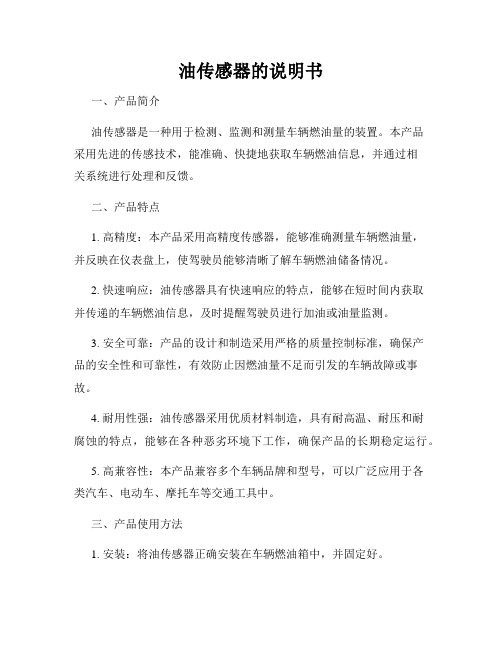
电容式汽车油位传感器说明书电容式汽车油位传感器采用电容传感器和液面感知传感器相结合的技术,不仅具有电容式液位传感器测量精度高、免维护的特点,同时还能消除电容式液位传感器易受温度和介质的影响的缺点。
它可以自动对不同温度和介质引起的测量误差进行精确地补偿,达到精确测量的目的。
该传感器整机无任何弹性部件和可动部件,耐冲击、免维护、长寿命、安装方便,可安装在各种场合,对汽油、柴油、液压油的油位及其它各种弱腐蚀性液体的液位进行准确测量。
该传感器是计量级测量仪器,具有很高的分辨率和测量精度。
它无须人工干预,自动校准,不存在温度漂移,且不受介质的变化影响。
也就是说同一支传感器,不管被测量的介质是水还是汽油或柴油,不管温度如何变化,它都能输出精确的液位高度信号。
彻底解决了乙醇汽油、甲醇燃料等介质难测量的问题,也同时解决了不同地区因油的标号不同和温度的巨大差异引起的测量误差问题。
该设备可以和GPS 车载定位终端或者其它终端相配合使用,组成精确的车辆定位及油耗管理系统。
可以评价车辆的使用情况和司机的驾驶水平,监视汽车在外加油情况,精确计算汽车百公里油耗,杜绝盗油、漏油、绕路、拉私活、公车私用、虚开发票等现象。
1、性能指标:● 检测范围:100~3000mm● 分辨率 :0.1%● 测量精度:0.1%● 测量最大误差:1mm● 探极耐温:-40~150℃● 探极直径:Φ18mm ● 输出信号:4~20mA 、0~5V 、RS485通讯、RS232通讯、CAN 总线● 供电电源:DC7~42V ,需要特殊说明可定制5V 供电,● 额定功率:0.1W● 固定方式:螺纹安装M20×1.5或法兰安装,特殊规格可按要求定制2、使用说明:● 承压范围: -0.1MPa ~0.1MPa ● 环境温度: -30~85℃2.1输出线定义接口输出线采用4芯电缆线,接线定义如下RS232输出方式(YW-201C):黑线接电源地红线接电源正白线 RXD输入,接车机RS232发送端(TXD)棕线 TXD输出,接车机RS232接收端(RXD)RS485输出方式(YW-201D):黑线接电源地红线接电源正白线接RS485 A棕线接RS485 B。
液位传感器安装方法说明书

液位传感器安装方法说明书一、概述液位传感器是一种重要的仪器设备,用于测量和监测液体的高度或深度,广泛应用于工业、环境、农业等领域。
本安装方法说明书旨在提供液位传感器的正确安装步骤和注意事项,以确保传感器的稳定工作和准确输出。
二、安装前准备1. 阅读和理解液位传感器的技术规格和使用说明书,了解安装的具体要求和限制。
2. 确认传感器与待测液体的兼容性,并检查传感器的完整性和工作状态。
3. 准备必要的工具和材料,如螺丝刀、螺丝、密封胶等。
三、安装步骤1. 确定安装位置:根据实际需要,选择合适的位置安装液位传感器。
考虑到液位变化和测量的准确性,建议将传感器尽量安装在液体的垂直中心位置。
2. 清洁安装区域:使用清洁布或棉球清洁安装区域,确保传感器安装处干净,无尘、无油和无杂物。
3. 进行固定安装:根据传感器类型和安装方式,采取适当的固定方法。
如果是螺纹接口固定,先在安装区域打孔,并使用螺栓或螺丝进行固定。
如果是粘贴固定,使用适当的密封胶或者双面胶带进行固定。
确保传感器固定牢固并且与安装表面充分贴合。
4. 连接电源和信号线:将传感器的电源线和信号线安装到控制设备上。
确保电源连接正确无误,并避免电源和信号线与其他电源或电气线路相干扰。
5. 调整传感器位置:根据需要,对传感器的位置进行微调,以确保传感器与液体的接触或测量部位的准确性。
将传感器连接到控制设备,并进行调试和校准。
四、注意事项1. 安装前务必断电,并遵守相关的安全事项和操作规程。
2. 确保安装过程中传感器不受外力影响,并避免碰撞、振动或拉扯。
3. 对于非浸入式液位传感器,应确保传感器的测量部位完全暴露于待测液体中,并与液体充分接触。
4. 仔细检查安装完成后的传感器固定情况,确保固定牢固可靠,防止传感器松动或脱落。
5. 定期检查和维护液位传感器,确保传感器的正常工作和长期稳定性。
五、总结通过本安装方法说明书,您应该能够正确安装液位传感器,并确保传感器与待测液体的准确测量和监测。
数字式位置传感器ISA3的使用说明书

文件No.PS※※-OMT0001CN-C数字式位置传感器ISA3-※※A/B-※·开关2输出型OUT1:距离检测OUT2:压力检测 or 距离检测二选一使用前 安全注意事项 2关于产品 产品特征 7型式表示·型号体系 8 产品各部分名称及功能 14规格15规格表(ISA3) (15)规格表(减压阀) (17)规格表(2通电磁阀) (17)特性图 (18)外形尺寸图 (21)设置方法 安装.设置28配管方法 (28)设置方法 (31)配线方法 (36)构成图 (41)使用方法 设定方法概要 44测量模式 (45)临界值的设定 47 OUT1:临界值、OUT2:压力设定值变更模式 (47)OUT1出厂时的设定状态 (47)OUT2出厂时的设定状态 (48)设定前的准备 (49)设定方法 (49)功能设定 50功能选择模式 (50)出厂时的设定状态 (50)键盘锁定(设定密码) 64故障时 维护 65忘记密码的情况 66故障一览表67报警显示 (68)供给压力和显示的关系 (69)安全注意事项此处所示的注意事项是为了确保您能安全正确地使用本产品,预先防止对您和他人造成危害和伤害而制定的。
这些注意事项,按照危害和伤害的大小及紧急程度分为“注意”“警告”“危险”三个等级。
无论哪个等级都是与安全相关的重要内容,所以除了遵守国际规格(ISO/IEC)、日本工业规格(JIS)※1)以及其他安全法规※2)外,这些内容也请务必遵守。*1) ISO 4414: Pneumatic fluid power -- General rules relating to systemsISO 4413: Hydraulic fluid power -- General rules relating to systemsIEC 60204-1: Safety of machinery -- Electrical equipment of machines (Part 1: General requirements) ISO 10218: Manipulating industrial robots-SafetyJIS B 8370: 空气压系统通则JIS B 8361: 油压系统通则JIS B 9960-1: 机械类的安全性-机械的电气装置(第1部:一般要求事項)JIS B 8433: 产业用操作机器人-安全性等*2) 劳动安全卫生法 等注意 误操作时,有人员受伤的风险,以及物品损坏的风险。警告 误操作时,有人员受到重大伤害甚至死亡的风险。
比泽尔油位开关说明书
比泽尔油位开关说明书1. 引言比泽尔油位开关是一种用于监测和控制液位的设备,通过测量液体的高度来实现对液位状态的判断和控制。
本说明书将详细介绍比泽尔油位开关的特点、使用方法、技术参数和注意事项。
2. 产品特点- 比泽尔油位开关采用先进的压力传感器技术,能够精确测量液位高度,具有高度可靠性和稳定性。
- 开关采用耐腐蚀材料制作,适用于各种液体环境下的应用,如油、水等。
- 开关具备高精度控制功能,可根据需求进行自定义设置,实现液位的自动控制。
- 设备外壳采用防护设计,具有防水、防尘、防爆等功能,适用于各种恶劣环境下的使用。
3. 使用方法- 安装:将开关固定在液体容器的侧面或顶部,确保开关与液体接触的部分完全浸泡在液体中。
- 电源连接:将开关与电源进行连接,确保电源的正负极与开关的连接正确。
- 设置参数:根据需要,可以通过设备上的按钮或旋钮进行参数设置,如液位的上下限、报警功能等。
- 系统连接:将开关与控制系统或报警器等设备进行连接,以实现液位的准确监测和控制。
4. 技术参数- 测量范围:根据实际需求进行选择,常见的测量范围为0-5m。
- 精度:通常为0.5%FS,可以根据特殊要求进行调整。
- 输出信号:常见的输出信号有模拟信号(4-20mA)和数字信号(RS485等),可以根据具体需求选择。
- 温度范围:开关能够在-20℃至60℃的温度下正常工作。
- 防护等级:通常为IP65,可以根据需求提供更高的防护等级。
5. 注意事项- 在安装过程中,请确保设备与电源断开连接,以避免触电等危险。
- 定期清洁设备表面,并避免油污或其他液体侵蚀设备。
- 在设备工作过程中,及时调整参数和维护设备,以确保其正常运行。
- 如果发现设备存在异常情况或无法正常工作,请及时联系厂家或专业技术人员进行检修。
本说明书为比泽尔油位开关的使用者提供了详细的使用方法和技术参数,希望能够帮助用户正确地使用和维护设备。
如有任何疑问或需要进一步了解产品信息,请联系我公司客服部门。
- 1、下载文档前请自行甄别文档内容的完整性,平台不提供额外的编辑、内容补充、找答案等附加服务。
- 2、"仅部分预览"的文档,不可在线预览部分如存在完整性等问题,可反馈申请退款(可完整预览的文档不适用该条件!)。
- 3、如文档侵犯您的权益,请联系客服反馈,我们会尽快为您处理(人工客服工作时间:9:00-18:30)。
ES600操作手册
V1.4
南京埃森电子科技有限公司
目录
1.产品介绍 (2)
2.外观及规格 (2)
2.1外观 (2)
2.2规格 (3)
3.接线定义 (3)
4.截断和校准 (6)
4.1截断 (6)
4.1.1油箱高度测量 (6)
4.1.2细屑清理 (7)
4.1.3底塞固定 (8)
4.2油位传感器校准 (9)
4.2.1按键校准 (9)
5.安装及布线 (11)
5.1钻孔 (11)
5.2安装及固定 (12)
5.3布线 (14)
附录:通讯协议 (15)
1.产品介绍
ES600系列油位传感器是南京埃森电子科技有限公司独立研发,具有多项创新技术。
ES600系列传感器能连续的检测位水平高度,分辩率小于1mm。
可截断调节长度以适应油箱的高度;简易的安装法兰,不需要额外的螺丝固定。
宽电压输入,确保在各种情况下不受电压限制。
特色:
1.可以根据油箱高度任意截断。
2.一体化结构,无任何弹性元件,并且支持多种信号输出方式。
3.按键式现场校准,方便快捷。
4.宽电压输入
2.外观及规格
2.1外观
单位:mm
2.2规格序号
名称性能参数
1
采集原理
电容式2
尺寸100mm 至1500mm(最小可以检测100mm,最大可以检测1500mm)注意:在传感器底部会有5mm 盲区空间不能检测,特殊可定制。
3
电气参数输入电压DC:4—70V 4功耗0.13W/5V,0.19W/12V,0.38W/245信号输出方式
(可定制)电压输出:0—5V 数字信号输出:RS-232或RS-485通讯波特率选择:2400,4800,9600,57600,115200模拟电阻输出:10—500Ω
电流输出:4—20mA
6
检测液体类型柴油,生物柴油,煤油,汽油等7
使用环境工作环境温度:-40℃~+85℃保存温度:-40℃~+105℃8
材料铝合金9
防护等级IP6710
分辨率1mm 11精度±0.5%
3.接线定义
各接线孔定义如下表所列:
序号
项目定义1
A/R 电流/电阻输出2
Vo 电压输出3
RX/B RS232接收/485B 4TX/A RS232发送/485A
5V-电源地6V+电源正级模拟信号―电压输出接线:V+,V-,Vo
数字信号―RS232接线:V+,V-,RX,TX
模拟信号―4-20MA输出接线:V+,V-,A/R
模拟信号―电阻信号输出接线:V+,V-,A/R
数字信号―RS485接线:V+,V-,A,B
4.截断和校准
4.1截断
注意:油位传感器截断的长度最好不要超过整体长度的30%。
4.1.1油箱高度测量
注意:ES600的长度=L 油箱的高度=H
ES600的长度L=油箱高度H +6mm.
油箱高度
H 油箱截面图
H
L
4.1.2细屑清理
截断后,油位传感器底端的金属细屑的清理。
用毛刷清除锯断时产生
的细屑,防止内外管短路
在柴油中清理油位
传感器内管和外管
平整和干净
注意:截断后,管子截面应该平整,干净,不能出现锯斜,金属细屑清理不干净的情况。
4.1.3底塞固定
固定密封圈
插入底塞
固定底塞
4.2油位传感器校准
油位传感器的校准即调满,调零。
基本原理为分别在满油箱和空油箱时在油位传感器里记录一个满值和空值,定义油箱满油和空箱位置。
油位发生变化时,油位传感器产生相应的电信号变化,从而计算当前油位的高度。
注意:油位传感器截断后,必须需要重新校准。
调零和调满与检测的介质和液位的高度有关系,与油箱的容积无关。
因此也可以在室内进行此操作。
校准的方式有:
1)按键的方式
2)通过配置软件。
校准的环境:
1)现场校准
2)室内校准(制作一个容器,装满柴油,模拟油箱)
目前介绍通过按键的方式进行对油位传感器校准,校准必须是先调满后调零。
校准前,油位传感器需正常通电。
注意:本款油位传感器,必须需先调满,然后调零。
否则,请重新校准。
4.2.1按键校准
打开油位传感器顶端盖子。
如下图所示。
4.2.1.1按键说明
DOWN
调零键Menu
菜单或退出键UP
调满键1
调零指示灯-蓝色2
工作状态指示灯-红色3调满指示灯-蓝色
4.2.1.2调满
调满步骤:将油箱加满油,然后将油位传感器插入油箱
调满后,测试电压输出线Vo 的电压,应为5V 4.2.1.3调零
注意:本款油位传感器,必须需先调满,然后调零。
否则,请重新校准。
调零步骤:将油位传感器取出油箱,搁置在油箱外面,等待大约1分钟。
然后再对油位传感器进行
调零设置
按UP 键2秒
3-指示灯,每500毫秒闪烁一次
经过一段时间(约20-50秒),若调频完成后,则3-指示灯2秒闪烁一次
此时按下”UP ”键,记录当前值为满值.3-指示灯熄灭.完成调满
调零后,测试电压输出线Vo 的电压应为0V
操作小技巧:若是不小心按错按键,可短按MEUN 键退出当前状态,重新调试。
4.2.1.4检验
调满和调零后,测量Vo 线的电压:
空箱:Vo
为0V 半箱:Vo
约为2.5V 满箱:Vo 约为5V
5.安装及布线
5.1钻孔
钻孔位置的选择,在油箱的中心位置。
钻孔直径为45MM 。
钻孔位置按DOWN 键2秒
1-指示灯,每500毫秒闪烁.
经过一段时间(约5秒),若油位值稳定后,则1-指示灯2秒闪烁一次
按下”DOWN”键,记录当前值为零值。
1-指示灯熄灭,完成调零
钻孔钻头
5.2安装及固定
截断油位传感器到合适的长度,并对油位传感器进行调满,调零(校准后的油位传感器如果再次截断后必须重新调满,调零)。
钻孔后,然后通过法兰固定油位传感器。
法兰固定油位传感器:
注意:为了方便演示法兰固定,下面油箱为为自制油箱。
室内环境拍摄。
准备工具:4mm、3mm内六角扳手各一,安装附件包里附件。
将法兰与底座之间
先安装一个螺丝
操作小技巧:拧螺丝时应对称轮流加力,以保证各方向受力均匀,避免漏油。
将一孔垫片放在法兰与底座之间将五孔垫片放在底座上
用内六角扳手将法兰拨正,螺丝孔对齐将法兰放入开好孔
的油箱中
放入油箱俯视图
用3mm 内六角将4
个螺丝均匀用力紧固
放入油杆用4mm 内六角紧固4个螺丝安装完成
5.3布线
在车辆工作环境比较恶劣的地方,通过波纹管保护线束,避免线的老化,布线时,尽量沿着车辆的主线,每隔50CM左右用扎带系紧。
安装法兰拆解示意图
附录:通讯协议协议结构
设置波特率
注:传感器默认波特率为9600,若设置的波特率不在此四种范围内,则传感器不予以回应。
查询设置调零值
查询设置调满值
设置邮箱体积
读当前油位值
注:本指令返回当前油位值,高度百分比及当前油位升数,传感器开盖状况等信息。
当前油位升数:根据流量计保存的数值对计算体积或当前油箱大小和。
设置,查询及探测ID号
包头
注:ID号只能是0到99中的一个,设置查询只针对连接单个油位传感器,在对单个油位传感器,可以直接查询ID 号,探测可以向多个发,检测在线的ID号。
查询/设置阻尼
注:当设置小于5秒的,当做5秒,当设置大于600秒的当做600秒处理。
恢复出厂设置参数
注:恢复出厂设置,需重新标定零点值和满点值。