Butterworth有源抗混叠滤波器设计_林祥金
Butterworth有源抗混叠滤波器设计
研究与设计 电 子 测 量 技 术ELECTRONIC MEA SUREM ENT T ECH NOLOGY 第31卷第2期2008年2月Butterworth有源抗混叠滤波器设计林祥金 张志利 朱 智(西安二炮工程学院 西安 710025)摘 要:信号混叠是视频采样系统中的一种失真。
为了防止这种失真,本文设计了一个4阶的视频有源低通抗混叠滤波器。
通过对二阶Bessel、Butter wo rth和Chebyshev等多种滤波器的性能分析比较,本文采用Butterw or th滤波器来设计该抗混叠滤波器,电路的拓扑结构采用Sallen K ey结构,并采用高速双运算放大器(SN10502),以构造一个可放入狭小印刷电路板中的4阶But terw or th滤波器。
测量结果表明,该滤波器在视频频段内几乎不出现峰值、平坦度好,并且阻带抑制效果好。
微分增益和相位同样也很不错。
最后,还讨论了在设计视频有源滤波过程中应该如何根据实际应用选择运算放大器,如何选择电容、电阻值,如何布局布线以及如何消除振荡。
关键词:Butter wo rth滤波器;有源抗混叠滤波器;Sallen key中图分类号:T P273 文献标识码:ADesign of butterworth active anti aliasing filterL in Xiangjin Zhang Zhili Zhu Z hi(Second Artillery Engin eering In stitu te,Xi an710025)Abstract:Sig nal aliasing is an obvious distor tio n in high speed video sampling system.T o avo id that,this paper presents a design of a four o rder active anti aliasing filter using hig h speed dual o perat ional amplifier SN10502,which can be placed in a tiny P CB(P rinted Circuit Boa rd).A n o ptimum design of this filter is intr oduced.Results show that the designed filter o ffers g oo d flatness of f requency r esponse,g oo d effects of sto pband rejectio n,hig h differential g ain and hig h differ ent ial phase,and almost no peaking occurs w it hin video fr equency r ang e.Finally this paper ends w ith discussions on ho w to cho ose o per ational amplifiers based o n practical application,how to choo se capacit ance and resistance,how to eliminate oscillation and on how to layout.Keywords:Butt erw ort h filter;act ive anti aliasing filter;Sallen key0 引 言信号混叠是采样视频系统中的一个明显失真。
一种抗混叠滤波器的设计

一种抗混叠滤波器的设计郭红玉【摘要】针对信号采集时,频率混叠现象的发生,为了能够有效地提取有用信号,本文介绍了滤波器的设计原理。
通过分析混叠现象产生的原因,探讨了几种常见滤波器的特点并进行了比较;最后设计了一种基于二阶巴特沃斯带通抗混叠滤波器。
通过仿真结果可以得出,该滤波器具有通带衰减特性平坦,能够有效避免混叠现象发生,为工程实践提供了可靠的理论指导。
%Aim at signal acquisition, the frequency alias happened regularly, in order to getting available signals,the paper introduced the principle of filters. By analyzed the appearance of the signal aliasing phenomenon;discussed and compared the characteristic of several common filters; at last designed a kind of anti-alias filter which based on 2nd order band pass Butterworth filter. The filter had a smooth band pass damping, voiding alias happened, supplied reliable theory guide for engineering practice.【期刊名称】《电子设计工程》【年(卷),期】2015(000)003【总页数】3页(P110-112)【关键词】滤波器;抗混混叠;巴特沃斯滤波器;归一化【作者】郭红玉【作者单位】朔州职业技术学院山西朔州 036002【正文语种】中文【中图分类】TN99滤波是指从混杂的信号中提取有用信息的过程。
适用于放电信号的ButterWorth有源滤波器快速设计

首先要做的就是对类型的选择 , 在F i l t e r S o l u t i o n s  ̄ _ 个软件 中 共有 十种类型 , 每一 种类 型对 应的滤波器都有着各 自不 同的特点 。 下面 对 这 些 种 类 的 滤 波 器 及 其 特 点 作 简 要 描 述 。 ( 1 ) 高斯具有最 平滑的通过性 , 能够实现最小 时延。 ( 2 ) 贝塞 尔作为低通类型 , 其通带时延近乎恒定 。 ( 3 ) 巴特 沃斯具 通带平滑 , 且群时廷也 比较适 中。 ( 4 ) 切 比雪夫型具有最尖锐的过渡带 , 同时群时延也是最大的。 ( 5 ) 切比雪夫型与型产品性能正好相反 , 通带平滑 , 适 中群时延 , 和等波纹的阻带 。
3软件 介绍
F i l t e r S o l u t i o n s 的版本有很多 , 但 是 用 最广 泛 的 是V1 0 . 0 这 个 4滤波器设计 版本 。 本文 中笔者所应用 的便是这个版本 , 该软件 的操作界 面的主 在众 多滤 波器 中使 用最 多 的是带 通滤 波器 , 下 文 中将 利 用 i l t e r S o l u t i 0 n s 这一软件设计一种四阶带通滤波器 , 用来滤除放 电 要有6 个部 门, 分别对应滤波器设计过程 中的各个各项选择和设置 。 F 信号 中的杂 波 。 3 . 1滤 波 器类 型 选择
4 . 1电路 设 计 与 真
在这个过程 中, 要对滤波器类型和拓扑结构进行设置 。 电路的 设计 要与实际需求相符。 在选择 的有源带通滤波器 中 , 其 阶数设 定 为2 阶, 频率控制在4 k H冽 1 8 k Hz 之间。 以上参数设置后 , 观察 电路 中出现的理想值器 件 , 基于此调 整出与之相符 的实际值 器件 。 4 . 2仿 真 与 实测 对 比 仿真与实测会 出现很大 的差别 , 这是 因为多种参数 的共同影响 而造成 的 同时, 实际情 况下电阻和 电 容 都与理想相差甚多 , 在 数值 和属性上 都存在很大差异 , 因此在实测 的结果 中, 我们会发现各类 ( 6 ) 霍格拉斯与切 比雪夫 Ⅱ 型类似 , 但具有更尖锐过渡带 , 群 时 值的得出和结论都存在一定的差距 。 延相对 较高 , 具有更大的阻带衰减 。 其通带具有 轻微轨迹 。 5结谱 ( 7 ) 椭圆函数具有等轨迹 的通带 , 过渡带尖锐’ , 高群时廷 , 具有最 通过对设计过程 的详细阐述 , 我们可 以发现F l i t e r S o l u t i o n s  ̄ 大阻带衰减 。 滤波器 的设计过程起到了很好的简化效果。 虽 然仿真与实测存在一 ( 8 ) 自定义可通过输入S 参数来 自主构建器件 。 但是 已经可 以设 计 出与需求 十分相近 的滤 波器特性 。 ( 9 余弦的显著特点为 : 具备一致的频率反馈, 时延恒定 , 最佳 定 的差异 , F i l t e r S o l u t i o n s 的使用 , 大大简化了设 计过程 中的计 算和转换 等过 频率反馈为独立升余 弦函数 。 对于滤波器 的设计 十分有益 。 ( 1 0 ) 匹配的显著特点为 : 阶跃响应近似斜面值 , 其冲激反馈接近 程 , 独立脉冲值 。 ( 1 1 ) 延迟类似传输延迟 , 它偶尔用于对信号进行 时域上的延迟 。 3 . 2滤 波器 种 类选择 首选要对 的种类进行选择 , 此次应用的设计软件 中有多种滤波 器 可 以选 择 。
Butterworth (巴特沃斯)滤波器设计参考

可以看出 fc@1000Hz 有-3dB 的衰减。
6
3. 1 阶 Butterworth HPF 设计
1 z 1 s C1 1 z 1 1 z 1 1 H ( z) , set G (C1 1) (C1 1) z 1 C1 1 1 H (s) , s 1 G Gz 1 H ( z) 1 G (C1 1) z 1 B0 G, A0 1, B1 B0 , B2 0 A2 0
多项式因子
1 2 3 4 5 6 7 8
(Note: 参考 维基百科 “巴特沃斯滤波器”)
1
由此得到 d0=a0=aN=1 情况下的 Butterworth 多项式展开的系数表:
H (s)
d0 , a0 a N d 0 1 a 0 a1 s a 2 s 2 a N s N
Butterworth (巴特沃斯)滤波器设计参考
-- By Water 在嵌入式音频产品开发过程中经常会到 LPF(Low Pass Filter 低通滤波器)和 HPF(High Pass Filter 高通滤 波器),一般情况下都是离线用工具(如: Matlab)设计好滤波器的参数(Filter Coefficients)再应用到产品中 去。但有些状况下需要用户自己根据需求来实时(Real-time)调整 Filter Frequency Response (滤波器频率响应), 这种情形下就需要在嵌入式系统中实时根据客户的设定需求来产生相应的 Filter Coefficients。 下文就汇总出了 N 阶 IIR LPF & HPF Butterworth 滤波器系数的设计方法, 具体的算法原理推导可以参考陈佩 青《数字信号处理教程》一书,此处只给出工程上可以应用的结论。
基于光端机的Butterworth有源滤波器的改进型设计

基于光端机的Butterworth有源滤波器的改进型设计章小兵;金鑫;方挺【摘要】An improved five-order active Butterworth filter is designed according to characteristics of input video signal. Sampling frequency is increased to reduce filter order, the group delay and the frequency characteristic of the filter are also adjusted, and quality of input video signal is improved. The reconstruction filter is built with specialized chipfor filtering and driving of the output video signal. The fiber transmitting and processing terminal including improved filter and programmable controller is implemented.Simulation and experimental results show that the designed filter has the characteristics of flatter passband, bigger stop-band attenuation, and better group delay in the passband.%针对输入视频信号特点,设计改进型的五阶Butterworth有源滤波器.通过提高采样频率降低滤波器阶数,同时改善滤波器的频率与群延时特性,从而提高输入视频信号的质量;采用专用芯片搭建重建滤波器以对输出视频信号进行滤波及驱动,实现包含改进滤波器的视频信号光纤传输处理终端.仿真与实验结果表明该滤波器通带平坦、阻带衰减大、群延时特性好.【期刊名称】《安徽工业大学学报(自然科学版)》【年(卷),期】2012(029)003【总页数】5页(P242-246)【关键词】Butterworth滤波;群延时;视频;光纤传输【作者】章小兵;金鑫;方挺【作者单位】安徽工业大学电气信息学院,安徽马鞍山243002;安徽工业大学电气信息学院,安徽马鞍山243002;安徽工业大学电气信息学院,安徽马鞍山243002【正文语种】中文【中图分类】TP39光纤通讯以其频带宽、容量大、衰减小等优势给通信领域带来了革新,基于光纤的视频信号传输应用越来越广泛。
BUTTERWORTHFILTERDESIGN巴特沃斯滤波器的设计
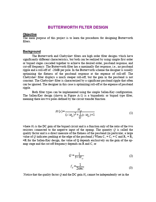
BUTTERWORTH FILTER DESIGN ObjectiveThe main purpose of this project is to learn the procedures for designing Butterworth filters.BackgroundThe Butterworth and Chebyshev filters are high order filter designs which have significantly different characteristics, but both can be realized by using simple first order or biquad stages cascaded together to achieve the desired order, passband response, and cut-off frequency. The Butterworth filter has a maximally flat response, i.e., no passband ripple and a roll-off of -20dB per pole. In the Butterworth scheme the designer is usually optimizing the flatness of the passband response at the expense of roll-off. The Chebyshev filter displays a much steeper roll-off, but the gain in the passband is not constant. The Chebyshev filter is characterized by a significant passband ripple that often can be ignored. The designer in this case is optimizing roll-off at the expense of passband ripple.Both filter types can be implemented using the simple Sallen-Key configuration. The Sallen-Key design (shown in Figure A-1) is a biquadratic or biquad type filter, meaning there are two poles defined by the circuit transfer function(1)where H 0 is the DC gain of the biquad circuit and is a function only of the ratio of the two resistors connected to the negative input of the opamp. The quantity Q is called the quality factor and is a direct measure of the flatness of the passband (in particular, a large value of Q indicates peaking at the edge of the passband.) When C 1 = C 2 = C and R 1 = R 2 =R for the Sallen-Key design, the value of Q depends exclusively on the gain of the op-amp stage and the cut-off frequency depends on R and C, or(2)(3) Notice that the quality factor Q and the DC gain H 0 cannot be independently set in the)(/)()12(/1s H o H s s o o Q ωω=++12f c RC π=13O Q H =−Sallen-Key circuit. Choice of the value of Q depends on the desired characteristics of the filter. In particular the designer must consider both the quality and the stability of the circuit. Calculations with different values of Q demonstrate that for the second order case the flattest response occurs when Q = 0.707, hence the maximally flat response of the Butterworth filter will also be realized when Q = 0.707. In addition the circuit is only stable when H 0 < 3. Higher values will result in poles in the right half-plane and an unstable circuit.The Butterworth filter is an optimal filter with maximally flat response in the passband. The magnitude of the frequency response of this family of filters can be written as(4)where n is the order of the filter and f c is the cutoff frequency . For a single biquad section, i.e., n = 2, the gain for which Q will equal 0.707, and hence yield a Butterworth type response, is found to be 1.586 from equation (2).In the case of a fourth order Butterworth filter (n = 4), the correct response can be achieved by cascading two biquad stages. Each stage must be characterized by a specific value of gain (or Q ) that achieves both a flat response and stability. For a fourth order Butterworth filter, the Q factors of the two stages must be Q = 0.541 and Q = 1.307. From (2) it follows that one stage must have a gain of 1.152 and the other stage a gain of 2.235. As a result the overall DC gain of the fourth-order Butterworth realized with two biquad stages will be equal to the product of the DC gain of the two stages, i.e., 2.575. The gain values required to cascade biquad sections to achieve even-order filters are given in Table A-I. Note that the number of biquad stages needed to realize a filter of order n is n /2.Other types of filters such as high pass, and bandpass filters can be designed the same way, i.e., by cascading the appropriate filter sections to achieve the desired bandpass and roll-off. The high-pass dual to the Sallen-Key low pass filter can be realized by simply exchanging the positions of R and C in the circuit of Figure A-1. Project1. Design a Butterworth lowpass filter with the following specification:Pass Frequency = 10KHzStop Frequency = 20KHzMinimum Attenuation in the stop band = 45 dB2. Design a Butterworth highpass filter with the following specification:Pass Frequency = 10KHzStop Frequency = 2KHzMinimum Attenuation in the stop band = 45 dB3. What is the minimum order for each filter?4.What is the passband gain of the filters?()H f5.Simulate the filters using Spice. Produce Bode plots for magnitude and phase for the two filters. Apply to the lowpass filter a 1V square wave and simulate the response of the lowpass filter. Do this for three cases: square wave frequency equal to 0.1 f c, 0.5 f c, and f c, where f c is the cutoff frequency of the lowpass filter. Apply to the highpass filter a 1V square wave and simulate the response of the highpass filter. Do this for three cases: square wave frequency equal to 10 f c, 2 f c, and f c, where f c is the cutoff frequency of the highpass filterDATA ANALYSISWrite a discussion of the results comparing the predicted values from your calculations with PSpice's predicted values. Make sure that your conclusions are supported by the data. Place all PSpice hard copies in the Report.AppendixFigure A-1 The Sallen-Key low pass filterPoles Butterworth(Gain) Chebyshev (0.5dB) λnGainChebyshev (2.0dB) λnGain2 1.586 1.231 1.842 0.907 2.114 4 1.152 0.597 1.582 0.471 1.9242.235 1.031 2.660 0.964 2.7821.068 0.396 1.537 0.316 1.891 6 1.586 0.7682.448 0.730 2.6482.483 1.011 2.846 0.983 2.9041.038 0.297 1.522 0.238 1.8791.337 0.5992.379 0.572 2.6051.889 0.8612.711 0.842 2.821 82.610 1.006 2.913 0.990 2.946。
基于Butterworth型三阶有源LPF的设计

基于Butterworth型三阶有源LPF的设计郭俊锋【期刊名称】《电子测试》【年(卷),期】2016(000)006【摘要】给出了一种利用运算仿真法实现三阶有源LPF的方法.利用Butterworth 函数逼近滤波器,对组成滤波器的元件进行了优化设计,使得滤波器的动态范围达到最大,频率特性符合Butterworth函数特点.利用EWB5.0C软件进行了仿真验证,符合设计要求,可应用于任意高阶的低通滤波器设计中.%A methodof implementation three active LPF with calculate & simulation is presented. Butterworth is approximated to filter, optimization design of filters' elements RC, so the dynamic range of the filter is the biggest.The feasibility is verified by simulating in EWB5.0C.【总页数】2页(P25-26)【作者】郭俊锋【作者单位】运城职业技术学院,山西运城,044000【正文语种】中文【中图分类】TN713【相关文献】1.基于光端机的Butterworth有源滤波器的改进型设计 [J], 章小兵;金鑫;方挺2.基于改进的Butterworth传递函数的高阶低通有源滤波器的设计 [J], 吕丹;陈文灵;张文夫;邓发升3.适用于放电信号的ButterWorth有源滤波器快速设计 [J], 曹珂杰;王聪;陈善璐4.基于改进型Butterworth传递函数的高阶低通滤波器的有源设计 [J], 李钟慎;洪健5.三阶Butterworth型极点配置方法的改进 [J], 孟吉红;徐军;邓海波;任克伟因版权原因,仅展示原文概要,查看原文内容请购买。
适用于有源电力滤波器的抗混叠滤波器设计

U 刖 吾
在 当代煤矿 的电网 中, 由于大量大功率和 非线性设备的应 用, 致使 部分煤矿 电 网中的谐波含 量已 经远远超 出国家 标准 ,
在 国 内外 专 家 学 者 的 努 力 下 , 源 滤 波 器 在 煤 矿 电 网 谐 波 治 理 有
八 八 厂 八 \
t增摄杠攥罄
抗 混叠 滤 波 器 。
: 十一十… 高 :… {: {: {: … }:一 :一1 : : } …: :… :… …: ; … : …: …: :- …: : 吲 十… …: : 哥: { … } { . }
一 。 。
{ 十 一十 … } } } { { { { 十 一 十 … … L 一 L _ 。 … … … … … … … … … _ _-
…
一
; -{ … … … ; ; : … ÷ … … } ; ; ; 一 - … … … … … … … … 一
一… — … : : 1 。… f : … … … … … … … … … … … … 一1
本文针对煤 矿电网谐 波主要分布在 3 0次以内的实际情况 , 通 过理论分析 , t b软 件验证 , 计出 了一款具 有针 对性的 mal a 设
珏 0 “ 栳 拦,暑 强 =¨ .
. .
.._..__ .-_..一 4 .'.3 -¨ 1
~ 墨■ . 0 1 “ 三 . 土譬.7 图 - 三 I . - 三 I 三 ; ] L
中 的应用越 来越广泛 。滤除谐 波的前提 是要准 确地检 测出谐 波, 目前广 泛应 用于 实 践的谐 波 检测 算法 为 F T, F T计 F 用 F 算信 号频谱时 , 免信号 产生混叠 是首要任 务 , 避 因此抗 混叠滤 波器作为信 号的预处理环节 , 它在有源电力滤 波器 中是必不可
- 1、下载文档前请自行甄别文档内容的完整性,平台不提供额外的编辑、内容补充、找答案等附加服务。
- 2、"仅部分预览"的文档,不可在线预览部分如存在完整性等问题,可反馈申请退款(可完整预览的文档不适用该条件!)。
- 3、如文档侵犯您的权益,请联系客服反馈,我们会尽快为您处理(人工客服工作时间:9:00-18:30)。
2 Butterworth 视频有源抗混叠滤波器设计
抗混叠滤波器的选择由 NT SC/PA L 视频制式规定的 模板来确定 。 带宽规定为 5 M H z(0 .1 dB), 截止频率为 6 M H z , 0 .1 dB 带宽范围内群延时差异为 3 ns 。 这样的性 能要求使得很难采用单纯的模拟滤波器来实现 , 但是通过 四倍过采样 可以将该 要求调 整为 27 M H z 处 12 dB , 32 M H z 处 40 dB 。使用软件或归一化曲线 , 发现 -3 dB 带宽 为 6 M H z 的 4 极点 Butterw orth 滤波器就能满足选择性 要求 。
最初 ,视频滤波器是一个无源的 LC 电路 。如今 , 高频 高速运算放大器推出使得在视频应用中 , 采用运算放大器 与 RC 相结合实现的有源滤波器比采用 LC 实现的无源滤 波器频率响应更好 、带宽更平坦 、通道间更匹配 , 而且还可 以获得尺寸更小 、效率更高的设计 。此外 , 由于有源滤波 器的精度取决于电阻和电容值的精度 , 因此精度相比无源 滤波器得到充分提高[ 2] 。
止频率 f c 为 6 MH z 。 这将 导致 整个 Butterw orth 波形 5 M H z频率时的增益为 -1 dB 。
图 5 采用 SN10502 双运算放大器的有源视频滤波器(+5 V 单电源 、AC 耦合输入)
电容应足够大 , 这样 PCB 的寄生电容才不至于影响电 容值 。但电容也不能太大 , 否则电阻值将会很小 , 以致放 大器将难以驱动如此小的电阻 。 PCB 的寄生电容在短走 线的情况下约为 1 pF(制造 PCB 的材料直接影响寄生电容 大小)。如果以 18 pF 作为电容元件的基本量级 , 就能将寄 生电容的影响降到最低 。 此外 , 该滤波器工作在 +5 V 单 电源下 , 并假设输入信号采用 A C 耦合 。如果输入 DC 电 平偏置水平能与电源电压和放大器的输入共模电压范围 兼容 ,输入信号就可能采用 DC 耦合 。
不论是用于抗混叠还是重建 , 滤波器都必须具备低通 特性 ,使视频的帧频能够通过 。因此 ,需要谨慎考虑 AC 耦 合 。 低通滤波器可以根据其幅度特性或用于描述它的多 项 式 来 分 类 (如 Bessel 、 Butt erw orth 、 Chebyshev 或 Cauer)[ 4] 。 图 1 和图 2 所示为 3 种最常用滤波器的特性 曲线 。
有源抗混叠滤波器有 2 种常用电路拓扑形式 :S-K(塞 仑-凯)形式和 M FB M ultiple-Feedback(多路反 馈)形式 , M FB 电路也叫无限增益电路或 Rauch 电路[ 5] , 如图 3 和图 4 所示 。
图 1 二阶低通滤波器幅频特性比较
图 3 二阶 S-K 低通滤波器
图 4 二阶 M FB 低通滤波器
选用何种电路结构来设计滤波器以获得较好的性能 , 有经验表明 , 如果所设计的滤波器是单位增益滤波器 , 并 且极对 Q 值比较低(比如 Q <3)的话 , Sallen-Key 滤波器是 一个不错的选择[ 6] 。
基于以上考虑 , 本文中的设计采用 T I 公司的高速双 运算放大器(SN 10502[7] ), 来构造一个可放入狭小印刷电 路 板 中 的 4 阶 But terw orth 滤 波 器 。 如 图 5 所 示 。 SN10502 的增益带宽为 60 MH z , 是一种采用单电源供电 和轨至轨输出方式的放大器 。 这些特点使 SN10502 成为 该类应用的最佳选择 。
该滤波器有两级 , 每一级都由一个 SN10502 运算放大 器采用 Sallen-Key 方式来实现 。 每级各提供两个极点 , 因 此整个滤波器需要一个双运算放大器器件以构成完整的 4
· 67 ·
第 31 卷
电 子 测 量 技 术
阶滤波器 。第一级为单位增益 , Q 值为 0 .54 ;第二级的增 益为 +2 , Q 值为 1 .3 。这些 Q 值可形成一个 Bu tterw orth 滤波器 。 为确保滤波器在整个视频频段内的平坦性 , 取截
摘 要 :信号混叠是视频采样系统中的一种失真 。 为了防止 这种失真 , 本文设 计了一个 4 阶的视频 有源低 通抗混 叠 滤波器 。 通过对二阶 Bessel 、But te rwo rth 和 Cheby shev 等多种滤波器 的性能分析 比较 , 本文采用 Butterw o rth 滤波 器 来设计该抗混叠滤波器 , 电路的拓扑结构采用 Sallen-K ey 结构 , 并 采用高速 双运算 放大器(S N10502), 以构 造一个 可 放入狭小印刷电路板中的 4 阶 Butterw or th 滤波器 。 测量结果表明 , 该滤波器在 视频频段 内几乎不出 现峰值 、平坦 度 好 , 并且阻带抑制效果 好 。微分 增益和相位同样也很不错 。 最后 , 还讨论了在设计视频有源滤 波过程中应该如何根 据 实际应用选择运算放大器 , 如何选择电容 、电阻值 , 如何布局布线以及如何消除振荡 。 关键词 :Butter wo rth 滤波器 ;有源抗混叠滤波器 ;Sallen-key 中图分类号 :T P 273 文献标识码 :A
图 2 二阶低通滤波器相频特性比较
从图 1 和图 2 分析可以得出 , 巴特沃斯滤波器有着最 为平坦的通带幅值响应 , 但高于截止频率的衰减度不是很 大 , 且相位线性度不是很好 ;贝赛尔滤波器的相位特性最 好 , 但高于截止频率的衰减度最小 , 且通带幅值响应不是 很好 ;而切比雪大滤波器在高于截止频率时有着最大的衰 减度 , 但相位线性度最差 .且在通带范围内会发生谐振现 象 。 由于视频滤波器要求良好的相位线性特征 , 即在整个 视频频段内都应具有十分恒定的相位延迟 , 同时要求幅度 响应 的 平 坦 度 要 好 。这 两 方 面 的 参 数 要 求 使 得 Butterw orth 滤波器成为一个不错的选择 。
0 引 言
信号混叠是采样视频系统中的一个明显失真 。 当超 出视频频段范围的高频信号(例如外部无线发射信号或本 地时钟信号)通过模数转换器的采样过程混叠回视频频段 时 , 就会产生混叠现象 。 在模数转换器之前放置一个视频 抗混叠滤波器就可防止这种失真 。 当利用数模转换器重 建数字化的视频信号时 , 将导致视频信号在较高频率上被 复制 ,从而也会引起图像失真 。 这类失真信号可通过在数 模转换器之后加入一个视频滤波器来消除[ 1] 。
定最佳的设计 。
1 滤波器的性能比较
二阶有源低通滤波器的传递函数可表示为 :
A(s)=a 0
Au +a1s
+s2
(1)
林祥金 等 :But t erwo rt h 有源抗混叠滤波器设计
第2期
Au 为通带增益 , 滤波器的特性即由作为二次多项式的 分母决定 ,当 a0 和 a1 优化为不同的值时 , 便可设计出不同 类型的滤波器 。
Design of butterworth active anti-aliasing filter
Lin Xiangjin Z hang Zhili Zhu Z hi (Second A rti llery Engi neeri ng In sti tu te , Xi' an 710025)
Abstract :Sig nal-aliasing is a n obvious disto rtio n in high-speed video sampling sy stem .T o avoid that , this pape r presents a design of a four-o rder active anti-aliasing filter using hig h speed dual o pera tional amplifier S N10502 , which can be placed in a tiny P CB (P rinted Circuit Boa rd).A n o ptimum desig n of this filter is intr oduced.Results show that the designed filter o ffers g oo d flatness of f requency re sponse , g oo d effec ts of sto pband rejectio n, hig h differential g ain and hig h diffe rential phase , and almost no peaking occurs w ithin video fr eque ncy r ang e .Finally this paper ends with discussions on ho w to cho ose o per atio nal amplifier s based o n practical applica tion , how to choo se capacitance and resistance , how to eliminate o scilla tion and on how to layout . Keywords:Butte rw or th filter ;active anti-aliasing filter ;Sallen-key
以下是一级 Sallen-Key 滤波器的转换函数 : A(s)=
Au (R1 · R2 · C1 · C2)· s2 +(R1 · C1 +R2 · C1 +R1 · C2 ·(1 -A u))· s +1
(2)
式中 :Au 为通带增益 , Au =1 +RR43 或 A u =1(对于第一级 的情况)。
研究与设计
Hale Waihona Puke 电 子 测 量 技 术 ELECT RONIC M EA SU REM ENT T ECH NOLOG Y