信城通桌面安全套件安装手册
信城通桌面安全套件安装说明win2003
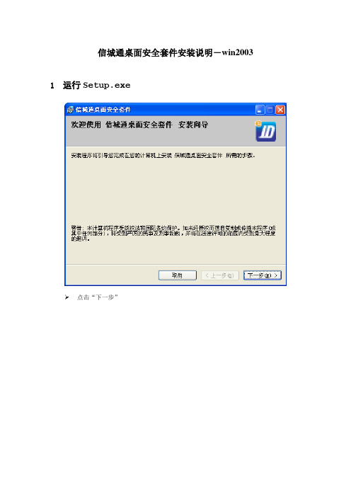
信城通桌面安全套件安装说明-win2003 1运行Setup.exe点击“下一步”在“浏览”中可以选择将此程序安装的目录 点击“下一步”点击“下一步”点击“是”重新启动机器点击“关闭”以上完成了程序的安装过程2重新启动操作系统后,发现新硬件同时桌面上弹出“欢迎使用找到新硬件向导”点击“下一步“点击“仍然继续“点击“完成“3插入硬件key后,发现新硬件同时桌面上出现“找到新硬件向导“点击“下一步“点击“仍然继续“点击“完成“看到出现后,就完成了驱动程序全部安装,可以开始使用。
4驱动安装没有发现图标的处理方法驱动安装完成以后,在桌面右下角没有出现图标,请按如下步骤操作检查驱动程序是否装成功:从电脑左下脚开始—程序—信城通桌面安全套件—桌面安全套件检查工具,如图所示:如果出现如下图红线所示内容,则表示驱动程序没有安装成功遇到如上情况,请您按照如下方法操作:在桌面上找到“我的电脑”这一项,右键点击“我的电脑”在显示的菜单栏点击“属性”,如下图:出现如下界面,然后点击“属性”如下图红线所示:出现如下界面,点击“设备管理器”出现如下界面,双击“智能卡阅读器”,如下图红线所示:双击“智能卡阅读器”以后如果显示如下图红线所示内容则表示驱动正常可以使用双击“智能卡阅读器”以后如果下面显示“未知设备”如下图红线所示,则说明驱动安装有问题“未知设备”上点击右键,在出现的菜单中点“更新驱动程序”,如下图所示:出现“硬件更新向导”的界面把向导按照提示的步骤完成选择“否,暂时不(T)”,点击“下一步”选择“自动安装软件(推荐)(I)”,点击“下一步”点击“仍然继续”点击“完成”按钮,完成了硬件更新向导。
把电子密钥重新插入电脑,右下脚出现图标,表示电子密钥可以正常使用。
艾克斯顿TeamWork Connect 300套件安装指南说明书

1TeamWork ® Connect 300 Kit • Installation GuideTransmitterReceiverCATx Cableup to 230' (70 m)Figure 1. TeamWork Connect 300 Application DiagramFigure 1 shows a typical TeamWork Connect 300 application. Digital or analog input devices (for example, laptops, or tablets) connect to the HCT 103 switching transmitter, using Show Me cables. The transmitter converts the analog and digital inputs into a proprietary digital signal. The proprietary signal passes along the CAT x cable to the HCR 102 scaling receiver where it is converted to HDMI.TeamWork Connect 300 Kit Included Parts• One HCT 103 transmitter • One Extron VGA Show Me cable • One HDMI display cable • One HCR 102 receiver•Two Extron HDMI Show Me cables•One CAT x cable•One 12 VDC, 3.0 A Extron power supplyRear Panel FeaturesHCR 102 ReceiverFigure 2. Rear Panel FeaturesA Power inputB Audio input (transmitter only)C VGA input (transmitter only)D HDMI inputsE CAT x cable connectorF Contact and Tally ports (transmitter only)G HDMI/CEC output (receiver only)H Audio output (receiver only)I COM port (receiver only)J IR port (receiver only)K Digital I/O (receiver only)LLAN port (receiver only)TeamWork Connect 300 Kit • Installation Guide (Continued)2Display RequirementsThe TeamWork Connect 300 kit is designed to work with most brands and models of flat panel displays available worldwide by sending CEC driver commands to turn the display power on and off.Some displays may not work with the specific CEC commands sent by the receiver. This may require modification to the Global Configurator Plus and Professional (GCP) project file. Other displays may not work with any CEC commands. This requires the system to be reconfigured to use an alternative signal, such as IR.Test the display thoroughly prior to installation or mass deployment of TeamWork systems. For optimum performance, consider the following when selecting the displays for your TeamWork installation:• Sleep mode — To use the TeamWork Connect 300 default features with a display that has a sleep mode option (sometimes called “auto sleep”), you should disable that option. This can usually be done with the menu settings for the display.•Resolution — The HDMI signal sent from the HCR 102 scaling receiver to the display has a resolution of 1080p. If the display does not support 1080p, reconfigure the receiver to produce a signal with a suitable resolution, using the on-screen display menu and front panel controls or the Extron PCS software.•Audio — Audio from source devices is supported in the TeamWork system by routing it as an embedded audio signal to the display for playback via integrated speakers. Most displays with HDMI inputs and integrated speakers work this way. Some professional or commercial grade displays do not have integrated speakers and will not support audio playback. Typically,source devices with HDMI output connectors embed audio onto the HDMI connector.Figure 3. Cabling the TeamWork Connect 300 Kit1 Connect the Transmitter to the Receiver (see page 3)2 Connect the Receiver to the Display Device (see page 3)3 Connect the Show Me Cables to the Transmitter (see page 3)4 (Optional)Connect Analog Audio Input (see page 4)5 Connect Power to the Receiver (see page 4)6 Connect the Show Me Cables to the Source Devices (see page 4)7 Power on the System (see page 4)3Connect the Transmitter to the ReceiverUse the provided CAT x cable to connect the CAT x ports of the transmitter and receiver (see figure 2, E ). The CAT x cable carries AV signals from the transmitter to the receiver. It also carries power from the receiver to the transmitter, so that the transmitter does not need a separate power supply.Connect the Receiver to the Display DeviceConnect the HDMI/CEC output port on the receiver (see figure 2, G ) to an AV device that supports CEC control. Use the provided LockIt cable lacing brackets to secure the HDMI connectors (see the HC 404 System User Guide for details).The HC 404 system uses CEC driver commands sent to the display to automatically turn display power on or off based on whether or not an active signal is detected at any input. This feature is built-in and works “out of the box” without need for additional configuration.Connect the Show Me Cables to the TransmitterThe Extron Show Me cables are for use with Extron TeamWork systems. They feature a Share button for remote input sourceHDMI Show Me cableINPUT(to source device)OUTPUT (to transmitter)pigtail for contact closure and tally (to transmitter)VGA Show Me cableINPUT(to source device)OUTPUT (to transmitter)closure and tally (to transmiter)Figure 4. Show Me CablesThe output end of the cable has either a VGA or HDMI connector and a three-conductor pigtail.1. Connect the VGA or HDMI connnector to the appropriate inputport on the transmitter (see figure 2, C and D , on page 1).Use the provided LockIt ® cable lacing brackets to secure the HDMI connectors (see the HC 404 System User Guide for details).2. Connect the black (Tally Out) and red (Contact In) pigtail wiresas shown in figure 5. The number adjacent to the Tally Out and Contact pins must correspond to the video input on the transmitter.• Input 2 is the VGA source.•Inputs 3 and 4 are the HDMI sources.3. Press the Share button to switch the connected source tothe presentation display. Pressing the Share button creates amomentary contact closure, which triggers the switcher to select the connected source device. If a tally output is connected, the button lights blue.HCT 103Transmitter Rear PanelFigure 5. Contact and Tally Wiring to TransmitterTeamWork Connect 300 Kit • Installation Guide (Continued)4Connect Analog Audio Input(Optional) For analog audio sources, connect the source device to the audio input 3.5 mm tip-ring-sleeve (TRS) connector on the transmitter (see figure 2, 2). The cable is not provided.Wire the connector as shown in figure 6.3.5 mm Stereo Plug(unbalanced input)Figure 6. Analog Audio InputConnect Power to the ReceiverConnect the HC 404 receiver to the provided 12 VDC, 3 A power supply (Extron PS 1230). The receiver provides power to the transmitter over the CAT x cable.R– ReturnRidged• Receiver front panel • Connect an included HCR 102 Front PanelFigure 7. Connecting Power to the HC 404 ReceiverConnect the Show Me Cables to the Source DevicesThe input end of the cable has a single VGA or HDMI connector. Connect this end to the appropriate input source. Use the provided LockIt cable lacing brackets to secure the HDMI connectors (see the HC 404 System User Guide for details).Power on the SystemIf required, power on the input devices and connect power to the display.Testing the SystemThe TeamWork system has been pre-configured so that once all the connections are made and the devices are all powered on there should be no need of further configuration for the system to work. To ensure that the system has been set up correctly, follow these steps:1. Power on the source devices.2. Press the Show Me button to select one of the source devices. If that source device is providing a video signal, the receiversends CEC commands that automatically turn the display power on and the display shows the signal from the selectedsource device.The LED button on the selected Show Me cable lights blue (if the source device provides sufficient power).3. Press the Show Me button for another of the source devices. Confirm that the display is showing the signal from the secondsource device.When the button on the second Show Me cable is pressed, the LED lights blue and the LED on the first cable is switched off.4. Press the Show Me button for the final source device. Confirm that the display is showing the signal from the third sourcedevice.When the button on the third Show Me cable is pressed, the LED lights blue and the LED on the second cable is switched off.5. Disconnect all the Show Me cables from the source devices.After about 30 seconds without an input signal, the display should turn off.After about 3 hours of inactivity (without changing the input), the display also turns off.6. Connect a Show Me cable to a source device and press the Show Me button on that cable.As soon as an active video signal is detected, the display should automatically turn on.TroubleshootingThe TeamWork Connect 300 system is pre-configured with a Global Configurator Plus and Professional (GCP) file to work, as shipped from the factory. The system uses CEC driver commands sent to the display to automatically turn display power on oroff.This section lists some of the most common issues and provides suggestions for dealing with them:• No Image on the Display• Show Me Button LEDs Stay Off When Pressed• The Display Does Not Automatically Turn On• The Display Stays On and Never Turns OffNo Image on the DisplayCause 1 — There is a problem with the source device:Solution — Verify that the source device is powered on and outputs an active signal.Cause 2 — Cable connections are incorrect:Solution — Verify that the cable from the transmitter is connected to the current HDMI input.Cause 3 — Display is off:Solution 1 — Verify that the display is in the on state.Solution 2 — The TeamWork system turns the display on and off by CEC. If the display has a sleep mode feature, disable thisfeature to prevent the display from accidentally powering off.Cause 4 — The display has a problem:Solution — Verify that the display functions correctly.Cause 5 — The display cannot show video at the incoming resolution:Solution — By default, the receiver puts out a signal with a resolution of 1080p. If that is not compatible with the display, theuser can change the receiver output resolution using Extron PCS software or the on-screen display menu. Contact an Extronsupport representative (see the phone numbers at /company/contactus.aspx).56TeamWork Connect 300 Kit • Installation Guide (Continued)© 2017 Extron Electronics All rights reserved. All trademarks mentioned are the property of their respective owners. Show Me Button LEDs Stay Off When PressedCause 1 — The cable is not plugged into a source device that is producing an active video output signal:Solution — Verify that the source device is on and producing an active signal.Cause 2 — Contact or tally wiring is incorrect:Solution — See Connect the Transmitter to the Receiver (page 3) to ensure the contact and tally pins are correctly wired.Cause 3 — The transmitter is not powered on:Solution — Verify that the transmitter is powered on . The HCT 103 front panel power LED lights if the device is receiving power. If it is being powered remotely by the receiver, ensure the CAT x cable between the transmitter and receiver isconnected correctly.Cause 4 — There is a problem with Show Me cable:Solution — Try connecting the video source to a different cable. If the second cable works correctly, there may be a problem with the Show Me cable. Contact an Extron support representative (see the phone numbers at /company/contactus.aspx ).Cause 5 — There is a problem with transmitter:Solution — If none of the cables work correctly, there may be a problem with the transmitter. Contact an Extron support representative (see the phone numbers at /company/contactus.aspx ).Cause 6 — The source device does not output +5 V:Solution — This is a problem with the source device. HDMI specifications require pin 18 to carry a +5 V output and VGAspecifications require pin 9 to carry a +5 V output. If the source does not provide power, the LED on the Show Me cable does not light but switching between sources should occur correctly.The Display Does Not Automatically Turn OnThe HC 404 system sends CEC driver commands to the display to turn display power on or off. The system is configured to power on the display if an active signal is detected on any input. If no active signal is detected, the display is powered off.Cause 1 — Incorrect wiring:Solution — Check that the HDMI cable between the receiver HDMI/CEC output to the display is correctly connected.Cause 2 — There is no video signal present at Show Me cables:Solution — Verify that an active signal is present at the input of any of the Show Me cables.Cause 3 — Display power is out of sync:Solution — The display is in standby mode. Turn on the display using the remote control or the physical power button.Cause 4 — Display has sleep mode enabled:Solution — Go to the menu for the display and disable the sleep mode feature. Turn on the display using the remote or physical power button.Cause 5 — Display is not compatible with the specific CEC commands sent by the receiver:Solution — Reconfigure the GCP project file to add a user defined control string (see the Universal Display Driver Communication Sheet at ).Cause 6 — Display does not support any CEC commands:Solution — Reconfigure the GCP project file to use an alternative method, such as IR, to turn display power on and off (see the Global Configurator Plus and Professional Help File ).Cause 7 — Display supports CEC commands but this feature needs to be enabled:Solution — See the user guide for the display.The Display Stays On and Never Turns OffCause 1 — Video signal is present at Show Me cables:Solution — Verify that no active signals are present at the inputs of any of the Show Me cables. The TeamWork system is designed to turn off the Display only when no video signals are present on any input.68-3266-01 Rev A12 17。
网上报检系统用户操作手册
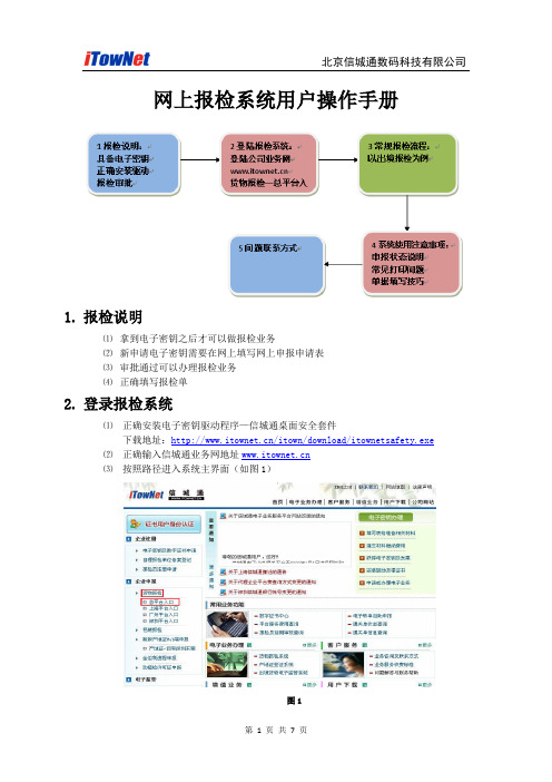
网上报检系统用户操作手册1.报检说明⑴拿到电子密钥之后才可以做报检业务⑵新申请电子密钥需要在网上填写网上申报申请表⑶审批通过可以办理报检业务⑷正确填写报检单2.登录报检系统⑴正确安装电子密钥驱动程序—信城通桌面安全套件下载地址:/itown/download/itownetsafety.exe⑵正确输入信城通业务网地址⑶按照路径进入系统主界面(如图1)图1⑷正常进入总平台入口应有身份验证和输入口令的过程(如图2)图2注意:如果没有选择数字证书的界面或者驱动安装不正确,都会出现电子密钥错误的信息(如图3)图3⑸新申请电子密钥进入报检系统(图4)填写好网上申报申请表之后点“保存”,等待信城通管理员进行审批。
审批通过之后才能进入(图5)界面图4⑹审批通过之后进入报检系统主页面(图5)图53.常规报检流程(以出境报检为例)⑴登录出境报检主页面图6说明:中间显示的为历史单据,包括申报和暂存等所有状态的单据;下面为详细的回执信息;在需要查看回执信息的情况下,选择已受理成功的单据,下面就会有详细的回执信息可供查看;⑵新建报检单图7⑶填写单据图示说明“*”表示必须填写项“”表示必须填写项如果一单要报几种货物,要在写完一种之后点“添加”按钮才可以进行新的货物信息输入“”表示选择,所有后面显示此图标的都是需要点开该图标进行相应的选择的备注1、关于填写—有一些内容没有标记为必填,但是它是业务内容上很重要的数据,比如数量/数量单位、重量/重量单位等也都是必须要填写的,如不填写,系统会弹出要求填写的提示;2、其他内容可根据用户自己的业务需求来进行内容的填写;3、如遇到直接按回车“Enter”键不起换行作用的时候,请按“Shift+Enter”键关键项说明报检登记号企业的报检注册号码(10位)施检机构单据报到哪个检验检疫局即选择正确的局名称HS编码/货物名称中文HS编码为10位,在蓝色问号中选择HS编码按回车键直接弹出货物名称中文产地根据实际产地,正确填写货物总值/货币单位根据实际内容,正确填写包装数量/包装种类根据实际内容,正确填写用途直接选择正确内容HS标准量/HS标准量单位对应货物信息的数量/数量单位或者重量/重量单位自动弹出;合同号/贸易方式/输往国家根据实际内容,正确填写随附单据蓝色问号中直接选择厂检信息如需填写,请按照相关局里规定来填写功能按钮名称功能说明查询简介:在历史单据比较多的情况下,可以在左边输入相应信息,点“查询”按钮,可以直接找到需要查看的单据;优点:节省时间提高操作效率清空简介:把之前输入的查询信息全部清除优点:不用一项一项手动删除刷新简介:用来查看单据申报的时时状态新建简介:点击“新建”按钮打开一张空白的报检单打开简介:选择一单已有单据进行查看复制简介:选择一单已有单据再点击“复制”按钮,可以直接复制原报检单内容,不需要重复填写部分内容删除简介:选择需要删除的单据,点击“删除”即可打印简介:选择一单申报成功的单据,点击“打印”可以直接打印出报检单打印凭条简介:与打印功能相同返回简介:返回到总平台入口的主界面⑷暂存填写好单据上的内容之后先暂存,防止有输入错误的内容直接申报造成影响。
数字证书远程更新操作说明

数字证书远程更新操作说明目录数字证书远程更新操作 ______________________________________________________________ 1第一步、安装最新“信城通桌面安全套件”_____________________________________ 2第二步、格式化电子密钥______________________________________________________ 2第三步、更新证书 ____________________________________________________________ 5第四步、更新成功后注意事项_________________________________________________ 10更新过程中常见问题及解决方法_____________________________________________________ 11提示1:制作证书所必须的控件没有正确下载 ___________________________________ 11提示2:未知错误0X1B6-E_UNEXPECTED ________________________________________ 11提示3:证书制证状态检查证书状态非法 _____________________________________ 12提示4:Enroll环境有问题,或配置信息有误不能提供有效的CSP __________________ 12提示5:证书授权码不正确,请重新确认证书授权码 _____________________________ 13提示6:证书不存在_________________________________________________________ 13提示7:Windows Installer程序包有问题…… _____________________________________ 13提示8:按照操作说明多次尝试修复KEY都不成功 _______________________________ 14第一步、安装最新“信城通桌面安全套件”目前最新版本为V2.7.02,不支持安装在64位操作系统上。
icom Data Suite 快速安装指南说明书

These short operating instructions apply for the following devices of INSYS icom:▪ icom Data Suite/manualIt serves for installation on the INSYS Smart Device (router) and quick commissioning by the user. What is the icom Data Suite?The icom Data Suite is an additional application to be installed on an INSYS Smart Device (router) running the operating system icom OS. It permits to collect data and issue an alarm for example in case of a range violation of the monitored values. Moreover, it enables to exchange data with various cloud services.The icom Data Suite will be installed on the device as an own IP end point. Thus, it acts like aseparate network participant. This allows full control of the communication with other participants. Where do I get the icom Data Suite?In case of an INSYS Smart Device with icom OS from version 3.4, the icom Data Suite will be installed using a setup wizard that downloads the icom Data Suite directly from the INSYS icom Update Server.It can also be downloaded on our website in the Support / Documentation and Downloads menu in the Application software: Device Apps section.Where do I get a licence for the icom Data Suite?The icom Data Suite requires a valid licence file with the respective activated functionality. You’ll find an overview of the free and chargeable licences under /icom-data-suite on the Packages tab. To obtain a licence, please use the form on the Enquiry tab.What are the prerequisites for the installation of the icom Data Suite?The INSYS Smart Device (router) has the latest firmware (at least 2.4). An update can be executed in the web interface of the router in the Administration menu on the Update page.The Smart Device has been commissioned as described in the related Quick Installation Guide.Open the Inline Help using the buttonappears upon selecting the button。
城云视界 DX70 DX80 桌面终端完全使用手册说明书
协作云终端桌面宝DX70/DX80完全使用手册ce8.3Version 1.5城云视界(杭州)有限公司网站:电话:*************地址:杭州市上城区望江东路332号望江国际3号楼17层版权声明本文档版权归城云视界(杭州)科技有限公司所有,未经城云视界(杭州)科技有限公司书面许可,任何单位或个人不得以任何形式或任何手段复制或传播本文档的一部分或全部内容。
Copyright © 2017 City Cloud Vision (HangZhou) Technology Co., Ltd. All Rights Reserved.This document is proprietary to City Cloud Vision (HangZhou) Technology Co., Ltd., which regards information contained herein as its intellectual property. Under the copyright laws, no part of this document may be copied, translated, or reduced to any electronic medium or machine readable form, in whole or in part, without prior written consent of City Cloud Vision (HangZhou) Technology Co., Ltd.前言在迈向万物互联的时代,视频会议系统为我们提供了随时随地、畅享交流的新办公体验。
作为一种新型的沟通工具,视频会议系统通过逼真的音视频效果为企业带来身临其境的会议感受,帮助各地员工轻松实现“面对面”跨地域的沟通交流,从而节约时间、资源,提高工作效率,让企业在瞬息万变的竞争环境中赢得先机。
信锐产品 T4 套件 AP 安装手册说明书
T4套件产品安装指导深圳市信锐网科技术有限公司文档版本:00T400-001805-01版权所有 © 深圳市信锐网科技术有限公司 2015.保留一切权利。
1产品概述T4 套件支架所支持的AP外观如下图。
各型号AP参数详见信锐官网。
后续新产品使用T4 支架,但外观或接口上可能有所变化,请以实物图为准。
图 1-1产品正面图图 1-2产品侧面接口图2安装准备2.1 安全注意事项T4套件支架所支持的AP为室内型,必须在室内使用,为保证AP设备长期处于良好的运行状态,保证设备能正常工作及延长使用寿命,必须使系统处于规定的运行环境之中。
警告:为了避免对人和设备造成伤害,请在安装设备之前仔细阅读本书的安全建议。
请在专业的工程人员指导下安装设备,以下安全建议并不涉及所有可能出现的危险情况。
2.1.1安装选址✓选址不宜在温度高、有害气体、易燃易爆、易受电磁干扰(大型雷达站、发射电台、变电站)及电压不稳的环境中;应避开经常有大震动或强噪声且远离各种污染源的地方。
✓安装地应该干燥,避免安装在直接雨淋、易被溅水、易积水、渗水、滴漏、结露等地方。
✓在进行工程设计时,应根据通信网络规划和通信设备的技术要求,综合考虑水文、地质、地震、电力、交通等因素,选择符合通信设备工程环境设计要求的地址。
2.1.2温度、湿度要求设备工作的温度、湿度要求如下:项目参数范围工作温度-10℃~55℃存储温度-40℃~70℃工作湿度5%~95%(非凝结)存储湿度5%~95%(非凝结)2.2 安装工具进行室内型AP设备的安装以及调试工作,在进行到不同的阶段需要准备不同的工具与仪表。
请事先自行准备做好工具和仪表,以免在工作现场延误时间。
(本司不提供以下工具,请用户自备)2.3 物料准备安装支架为标配,里面包含塑料膨胀管、膨胀螺钉、普通螺丝,此安装支架可以壁挂安装也可以吸顶安装天花板上;关联产品需要自行准备。
壁挂、吸顶安装时涉及到的工程物料如下:关联产品如下:3产品安装3.1 安装流程T4 套件支架所支持的AP仅适用于室内安装,支持以下安装方式:吸顶安装方式、壁挂安装方式、桌面放装方式。
桌面终端安全操作手册
六.安全操作习惯
1.离开座位时电脑桌面上禁止有打开的公司敏感资料。人员离 开电脑前,应将与公司相关资料关闭,并将电脑处于锁定状态 2.禁止使用来路不明的外设如USB等,如果确实因为工作需要, 在使用外接设备前,必须经过电脑防病毒软件的扫描后,方可 使用 3.在每天工作结束后,将台式计算机关机;便携电脑妥善保管, 如锁入文件柜。
5.锁定无效登录 (1)针对Windows 2000/XP 为了防止他人进入电脑时,反复用猜测密码的方式登录,我们可以锁定无效登录,当密 码输入错误达设定次数后,便锁定此账户,在一定时间内不能再以该账户登录。设置方法是: 进入[控制面板],依次展开[管理工具]→[本地安全策略],出现“本地安全设置”窗口(如 图1),在左侧列表中打开[账户策略]→[账户锁定策略],在右边双击“账户锁定阀值”,在弹 出的设置对话框中输入无效登录的次数(设定为3次),确定后系统自动将锁定时长和计数器 清零的时长设置为“30分钟”。
进入控制面板依次展开进入控制面板依次展开管理工具管理工具本地安全策略本地安全策略出现本地安全设置窗口如图图11在左侧列表中打开在左侧列表中打开账户策略账户策略账户锁定策略账户锁定策略在右边双击账户锁定阀值在弹出的设置对话框中输入无效登录的次数设定为弹出的设置对话框中输入无效登录的次数设定为33次确定后系统自动将锁定时长和计数器清零的时长设置为器清零的时长设置为3030分钟
3.把系统administrator帐号改名 windows中的administrator帐号是一个众所周知的账号,这意味着别人可以一遍又一边 的尝试这个帐户的密码。把Administrator帐户改名可以有效的防止这一点。
4. 使用安全密码 一个好密码对于一个网络是非常重要的,但是它是最容易被忽略的。帐户应该要求用户首次登陆的时 候更改成复杂的密码,还要注意经常更改密码。针对系统密码的安全,运用Windows 7系统工具“本地安 全策略”(控制面板\系统和安全\管理工具\账户策略\密码策略) Windows XP 系统通过 控制面板\管理工具\账户策略\密码策略(控制面板需要切换至经典视图模式)完 成以下要求的操作: (1)启用系统密码的复杂性要求:包含大小写字母,特殊符号,数字; (2)强制用户密码长度不得少于8位; (3)设置密码最长使用期限为90天; (4)强制用户使用旧密码至少30天后才能更改密码,并且不能更改为之前连续使用过的 3个密码中的任 何一个。
瑞星企业终端安全管理系统软件3.0用户手册
瑞星企业终端安全管理系统软件3.0用户手册2019瑞星ESM下一代网络版3.0快速安装指南瑞星ESM 下一代网络版快速安装指南快速使用指南用于指导用户快速安装和使用瑞星ESM 下一代网络版。
指南中介绍了瑞星ESM 下一代网络版的安装方法。
请在安装瑞星ESM 下一代网络版前认真阅读本指南。
目录目录 (1)产品简介 (2)应用环境 (3)2.1. 数据中心 (3)2.2. 管理中心(manager) (3)2.3. 业务中心(bus) (4)2.4. 升级中心(ruc) (5)2.5. 补丁下载中心(rua) (6)2.6. Windows客户端(ep) (7)2.7. Linux客户端 (7)2.8. 远程管理控制台 (9)安装与卸载 (9)3.1. 安装 (10)3.1.1.服务器安装 (10)3.1.2.客户端安装 (17)3.2. 卸载 (22)3.2.1.服务器卸载 (22)3.2.2.客户端卸载 (24)3.3. 修复 (26)产品激活 (28)4.1. 授权管理 (29)4.1.1.产品授权 (29)4.1.2.静态授权 (29)4.1.3.导入授权 (30)系统登录 (30)产品简介瑞星企业终端安全管理系统软件(简称ESM3.0)是企业级内网安全管理软件产品,它为加强内网管理提供了一套统一的IT 安全解决方案,不但提供传统的防病毒、漏洞扫描等功能,还对网络环境中各计算机的信息、软硬件资源进行有效的管理和控制。
瑞星企业终端安全管理系统软件产品实质上不只是一个管理平台,企业用户可以根据自身的需求在其上布置具有不同管理功能的子产品。
本软件可以满足各类企业的不同需求,有针对性的解决企业遇到的各种安全风险,彻底改变了以往安全类软件功能过于笼统、不够灵活的缺点。
瑞星企业终端安全管理系统软件工作原理如下图:管理中心:是对企业全网进行统一管理的交互平台,用户通过管理中心就可以完成所有管理功能。
它实时反映防护体系内每台计算机情况,为管理员管理客户端计算机的使用情况提供了大量的依据。
Soft Sides Fountains with FLEXI-GUARD 安装与使用说明书
NOTE: WATER FLOW DIRECTION SERVICE STOP (NOT FURNISHED)FIG. 1INSTALLATION INSTRUCTIONS1. Wall should already be framed for the fountain using the positioning dimensions shown in Figure 3. Showndimensions pertain to installation location (framing must support up to 300 lbs. weight). These dimensionsare required for compliance with ANSI Standard A117.0.2. Attach wall plate assembly to wall as shown in Figure 3 using 5/16" x 2" long bolts and flat washers(not provided). Tighten securely. (Fastener must match wall type, i.e. lag screws for wood studs, bolts andanchors for masonary construction.)3. Install back panel. Place the upper edge of the panel above hanger on the wall. Slide panel down until itengages the hanger. Be sure back panel is firmly engaged before releasing it.4. Install rough-in plumbing as shown in Figure 3. Waste line should extend a minimum of 2" (51mm) thru theback panel. Run supply water inlet line thru back panel. Install a service stop (not provided). Turn on supplywater and flush thoroughly.5. Remove bottom access panel from fountain basin and save the screws. Install the fountain to the backpanel using (4) 5/16" x 3/4" long screws and washers (provided) thru holes in back panel. Tighten securely.6. Cut waste tube to required length using plumbing hardware and a trap (not provided) as a guide. Installhardware and trap. Tighten securely.7. Make water supply connections from service stop to the 3/8" O.D. unplated copper tube coming out of thefountain strainer (See Fig. 1). Turn on water supply and check for leaks. Newly installed water supply lineshould be insulated after leak check is completed. DO NOT SOLDER TUBES INSERTED INTO THE STRAINER AS DAMAGE TO THE O-RINGS MAY RESULT.8. These products are designed to operate on 20-105 PSI supply line pressure. If inlet pressure is above105 PSI, a pressure regulator must be installed in the supply line. Any damage caused by reason ofconnecting these products to supply line pressure lower than 20 PSI or higher than 105 PSI is notcovered by warranty.9. Check stream height from bubbler. Stream height is factory set at 35 PSI. If supply pressure varies greatly from this, adjust the screw on regulator item 10 by using a small screwdriver through the small holein the push button item 3 (See Fig.5). Clockwise adjustment will raise stream height and counter-clockwiseadjustment will lower stream height. For best adjustment stream should hit basin approximately 6-1/2"(165mm) from bubbler.10. Replace bottom access panel to fountain basin using screws provided. Tighten securely.TROUBLE SHOOTING AND MAINTENANCE1. Orifice Assy: Mineral deposits on orifice can cause water flow to spurt or not regulate. Mineral depositsmay be removed from orifice with a small round file not over 1/8" diameter or a small diameter wire.CAUTION: Do not file or cut orifice materials.2. Stream Regulator: If orifice is free of material deposits, regulate flow according to instruction 9 stated above.3. Actuation of Quick Connect Water Fittings: Cooler is provided with lead-free connectors which utilize ano-ring water seal. To remove tubing from the fitting, relieve water pressure, push in on the gray collar whilepulling on the tubing (See Figure 2). To insert tubing, push tube straight into the fitting until it reaches apositive stop, approximately 3/4".NOTE: WHEN INSTALLING REPLACEMENT BUBBLER AND PEDESTAL, TIGHTENLOCKNUT ONLY TO HOLD PARTS SNUG IN DO NOT OVER TIGHTEN.FIG. 6172223418SEE FIG. 6 OR 716151, 9, 1013192085, 7119BASINLocknutBASIN BUBBLER DETAILVANDAL RESUSTENT BUBBLER DETAILELKAY MANUFACTURING COMPANY • 2222 CAMDEN COURT • OAK BROOK, IL 60523 • 630.574.8484 • FOR PARTS, CONTACT YOUR LOCAL DISTRIBUTOR OR CALL 1.800.834.4816REPAIR SERVICE INFORMATION TOLL FREE NUMBER 1.800.260.6640。
- 1、下载文档前请自行甄别文档内容的完整性,平台不提供额外的编辑、内容补充、找答案等附加服务。
- 2、"仅部分预览"的文档,不可在线预览部分如存在完整性等问题,可反馈申请退款(可完整预览的文档不适用该条件!)。
- 3、如文档侵犯您的权益,请联系客服反馈,我们会尽快为您处理(人工客服工作时间:9:00-18:30)。
信城通桌面安全套件
安装手册
北京信城通数码科技有限公司
二零零八年七月
目录
1 信城通桌面安全套件安装流程 (1)
1.1 安装要求 (1)
1.2 启动安装 (1)
1.3 安装信城通桌面安全套件 (1)
2 检查信城通桌面安全套件安装情况 (5)
3 卸载信城通桌面安全套件 (7)
3.1 通过桌面安全套件菜单卸载 (7)
3.2 在控制面板卸载 (7)
1 信城通桌面安全套件安装流程
1.1 安装要求
信城通桌面安全套件支持Windows 98、Windows 98 se、Windows ME、Windows 2000、Windows XP、Windows 2003 server(即Windows .net)序列各个版本操作系统,要求计算机上已经安装IE V5.0以上版本的浏览器。
信城通桌面安全套件暂未支持Windows Vista操作系统。
1.2 启动安装
将“信城通桌面安全套件”安装盘(光盘或软盘)插入计算机的光盘驱动器或软盘驱动器,利用文件管理器打开目录“信城通桌面安全套件”,双击其中“”文件,安装程序将开始执行安装过程。
具体安装步骤可以参照随光盘附带的纸质操作手册。
如果是通过网络下载或通过其它途径获得“信城通桌面安全套件”的安装程序,请利用文件管理器找到该安装程序,双击后开始安装。
1.3 安装信城通桌面安全套件
如果计算机检查符合“信城通桌面安全套件”安装条件,则显示如下“欢迎”窗口:
单击“下一步”,则出现“选择安装文件夹”窗口:
如果你不希望安装到“文件夹”指定的缺省目录,而需要选择安装到其它目录,单击“浏览”则弹出“选择文件夹”窗口:
当选择好文件夹后,单击“确定”回到上一窗口。
“选择安装文件夹”窗口中的选择完成后,单击“下一步”则进入“确认安装”窗口:
如此时如要取消安装,请按下“取消”按钮取消安装;也可以按下“上一步”修改前面所做的选择。
当确认要进行安装时,单击“下一步”,安装程序将开始安装并显示安装进度:
安装完毕后将显示“安装完成”窗口。
在安装完成后,安装程序将根据安装中的具体情况,可能出现提示“重新启动计算机”的窗口。
如果没有出现“重新启动计算机”窗口时,信城通桌面安全套件安装完毕;如果出现,则必须重新启动机器后信城通桌面安全套件才安装完毕。
到此信城通桌面安全套件安装成功,您可以插入电子密钥进行网上电子业务。
插入钥匙后,电脑桌面右下角出现图标。
2 检查信城通桌面安全套件安装情况
信城通桌面安全套件配备了一个检查工具“信城通桌面安全套件检查工具”,用于检查信城通桌面安全套件的安装情况,以及检查信城通电子密钥及其中资料是否存在问题。
“信城通桌面安全套件检查工具”如下图:
运行“信城通桌面安全套件检查工具”将做以下检查:
●检测计算机运行环境、桌面安全套件版本和电子密钥驱动版本;
●检查信城通桌面安全套件是否遗失必要文件和注册项;
●检查接入的信城通电子密钥标识资料;
●检查接入的信城通电子密钥内证书、密钥对以及匹配情况;
●对接入的信城通电子密钥执行签名、验证、加密、解密、生成随机数、
计算数字摘要等操作等。
如果“信城通桌面安全套件检查工具”的运行正确完成,说明信城通桌面安全套件安装正确,接入的信城通电子密钥本身无问题(但不能说明信城通电子密钥内数据正确)。
如果运行中报错,将根据具体情况出现“修复信城通桌面安全套件”或“卸载信城通电子密钥驱动”按钮,可根据具体情况选择相应处理。
也可将运行报
告“套件检查结果.txt”文件提交电子密钥管理员,以便电子密钥管理员协助你处理解决问题。
使用细节请阅读“信城通桌面安全套件用户手册”。
3 卸载信城通桌面安全套件
3.1 通过桌面安全套件菜单卸载
在“开始”菜单中选择“信城通桌面安全套件”下的“卸载信城通桌面安全套件”菜单项启动卸载。
程序将自动检查是否存在使用信城通电子密钥的所有安装包。
如发现,将询问该安装包是否进行卸载,选择“是”将卸载该安装包,选择“否”将退出卸载。
3.2 在控制面板卸载
打开“控制面板”中的“添加和删除程序”,选择要删除的“信城通桌面安全套件”并单击“删除”按钮,确认后系统将完成删除工作。