[冲压发动机进气道]The effects of intake modification on a Ramjet engine
出口封闭的冲压发动机进气道激波振荡现象
低通滤波器滤波 ( 5kHz ) 和信号放大器后进入采集装 置, 采集装置采样频率为 20kHz。具体试验过程不再论 述, 就试验结果来讨论。试验表明, 进气道出口通道封 闭条件下进气道内部均发生了强烈的振荡现象, 规律明 Ma 为 2. 0 显, 频率和幅值稳定。图 5 为轴对称 L t2 模型、 状态下两个不同时刻的纹影照片。另外对一种二元进 气道进行封闭通道试验, 也验证了规律明显的激波振荡 现象, 可以清晰看到两个模型由于激波振荡引起的脱体 激波在上下游的位置变化。
607 第 32 卷 第 5 期 出口封闭的冲压发动机进气道激波振荡现象 理原因和进气道亚临界喘振之间有类似但不完全相同 的地方。国内对出口封闭的冲压发动机进气道内通道
[ 7 ] 白晓征等 激波振荡研究主要集中在数值模拟方面, 对来流马赫数 3. 5 的轴对称进气道进行了整流罩开启
Fig. 5
Ma = 2. 0 schlieren photo
经分析得到轴对称进气道内通道压力振荡随时间变化 关系以及 FFT 幅值分析。图 6 是 Ma 为 2. 0 轴对称 L1 模型试验各测点动态压力分析结果, 可以看到振荡包 2 、 3 含明显的基频以及 阶 阶等更高频率的谐波振动。 表 2 为轴对称进气道不同马赫数状态模型封闭端压力 幅频分析的最终结果。
对上述试验结果进行分析可得出如下结果 : 2 阶谐波和 3 阶谐 ( 1 ) 各静压测点都包含基频、 波, 基波的频谱十分明显, 且振荡主频率和长度近似呈 反比关系。 ( 2 ) 试验反映出通道末端的传感器压力幅值一般 要高于前方传感器的压力幅值, 说明通道越长, 压力振 幅越高, 近似为线性。 ( 3 ) 相同试验状态下各传感器的频率一致, 但存 在相位差, 这也直接证明了封闭通道内气流反复振荡 这一变化过程。 ( 4 ) 马赫数 1. 5 ~ 2. 5 进气道内通道均发生振荡 现象, 马赫数越高, 振荡强度越大, 这和进气道进口前
超燃冲压发动机一维稳态跨声速流动奇异初值问题的一个解法

超燃冲压发动机一维稳态跨声速流动奇异初值问题的一个解法崔涛;于达仁;鲍文【期刊名称】《中国航空学报(英文版)》【年(卷),期】2005(018)002【摘要】超燃冲压发动机燃烧室一维稳态跨声速流动方程在临界声速点存在奇异初值问题,现有的基于L'Hospital法则的求解方法在原理上存在较大的初值误差,影响一维稳态跨声速计算的精度.为此,本文提出了一种基于变量代换的改进算法,通过定义新的流动变量W=-Ma2+2Ma,构造出了非奇异的一维稳态跨声速流动方程.消除了微分方程的奇异性,有效的解决了一维稳态跨声速流动计算过程中存在的奇异初值问题.%Singular initial value problems arise in solving one-dimensional steady transonic flow of dual-mode scramjet. The existing solution method has the problems of large initial value errors in principles. This paper puts forward an improved algorithm based on variable transformation, and constructs a nonsingular one-dimensional steady transonic flow equation by defining a new variable. The improved algorithm can eliminate the singularity of the differential equation, and can solve the singular initial value problems of one-dimensional steady transonic flow of dual-mode scramjet.【总页数】5页(P97-101)【作者】崔涛;于达仁;鲍文【作者单位】College of Energy Science and Engineering,Harbin Institute of Technology,Harbin 150001, China;College of Energy Science and Engineering,Harbin Institute of Technology,Harbin 150001, China;College of Energy Science and Engineering,Harbin Institute of Technology,Harbin 150001, China【正文语种】中文【中图分类】V233.7因版权原因,仅展示原文概要,查看原文内容请购买。
火箭冲压发动机空气进气道性能的实验研究

火箭冲压发动机空气进气道性能的实验研究本文以火箭冲压发动机空气进气道性能为研究对象,旨在探究进气系统在负荷变化时的动态性能。
研究采用基于一维流体计算的非定常数值模拟,将系统在历程运行状态的进气系统性能与理想工况的性能进行比较并进行验证,并分析系统不同参数的影响,探讨了不同负荷条件下的进气系统性能变化情况。
摘要:本文分析了火箭冲压发动机空气进气道性能,采用基于一维流体计算的非定常数值模拟方法对进气系统在历程运行状态的性能进行模拟,进而探讨了不同负荷条件下的进气系统性能变化情况,为火箭冲压发动机优化空气进气道性能提供了参考意义。
关键词:火箭冲压发动机、空气进气道、非定常数值模拟、性能变化基于一维流体计算的非定常数值模拟方法可以为火箭冲压发动机优化空气进气道性能提供重要参考。
通过数值模拟,可以准确地获得火箭冲压发动机空气进气道的性能特点,从而进行故障诊断和系统参数的优化设计。
此外,该模型还可以提供实时的运行参数及其数据,快速反映运行状况,避免因系统持续运行而导致的损害或系统损坏,从而提高运行安全性和可靠性。
此外,通过数值模拟,可以进一步研究火箭冲压发动机空气进气道的设计工艺参数,优化内部结构,以及影响性能的其他参数,以达到最大效率并优化流量选择,同时有效提升运动性能。
通过数值模拟,可以深入研究火箭冲压发动机空气进气道的参数,探究进气系统在不同负荷条件下的动态性能,快速实现参数的优化设计,同时有效消除噪声并保护环境,从而更好地满足火箭冲压发动机的多种性能需求。
为了更好地利用以上技术,采用详细的计算流程可以更好地优化火箭冲压发动机空气进气道性能。
首先,需要确定进气系统的基本参数,如尺寸、结构,以及系统内部体积等。
然后,可以建立一维流体模型来进行计算,对系统运行状态的进气系统性能及理想工况的性能进行计算并比较,充分检验和证实其正确性。
此外,通过研究不同参数的影响,有助于深入了解系统的功能,提高优化精度。
此外,通过数值模拟,我们可以快速反映系统性能,及时发现存在的问题,从而有效地避免由于运行不当产生的系统损坏,减少维护和保养成本。
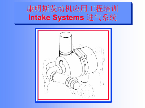
INTAKE(进气系统)
应用工程培训
w w
PURPOSE OF AN AIR INTAKE SYSTEM 进气系统的作用
w
向发动机提供清洁、干燥、温度适当的空气进行燃烧以 最大限度地降低发动机磨损并保持最佳的发动机性能。
w
在用户接受的合理保养间隔内有效地过滤灰尘并保持进 气阻力在规定的限值内。
Intake Systems 进气系统
Verification Procedures 评审程序
应用工程培训
FILTRATION 滤清性能
w w
设计评审 产品检查 Advisor 可以计算复杂系统的阻力 设计评审 安装测试,额定功率和转速下测试最复杂系统状态的阻力 设计评审 产品检查 安装测试(测试冷却能力时测量进气温升)
RESTRICTION 阻力
w w w
INLET LOCATION 进气口位置
w w w
Intake Systems 进气系统
Verification Procedures 评审程序
应用工程培训
SYSTEM PIPING & CONNECTIONS 系统管路和连接
w w w
设计评审 产品检查 必要时进行测试 设计评审 产品检查 必要时进行测试 --如果评审工程师根据以前的测试或经 验认为除水装置的性能值得怀疑时
应用工程培训
w
为什么需要进气系统 (续)
w
进气温度过低会导致柴油无法被压燃,发火滞后,燃烧 不正常---这又可引起冒黑烟、爆震、运转不稳(特 别是怠速时)和柴油稀释机油。
w
进气温度每降低33℃,燃烧温度下降89℃。
Intake Systems 进气系统
冲压发动机加速阶段进气道内动态特性
发 动机 的燃 烧室 , 大大 提高 导 弹 的容积 利 用 率 , 这 能 但
的 , 频 率 成 分 在 扩 压 器 长 度 增 大 时 消 失 。L 高 uP J
样 就必 须 在 冲 压 发 动 机 燃 烧 室 的 入 口端 安装 密 封 堵 等 数值 分 析 了冲压 发 动机进 气道 喘 振现象 。结果 表 喘振 来 自进 口处 的 局 部 流动 不 稳 定 以及 气 室 中的 盖, 亦称 为进 气道 出 口堵 盖 。在导 弹 助推 飞行 阶段 , 进 明 , 研 气 道 内通道 被 出 口堵 盖 封 闭 , 流 动 涉 及 进 气 道 的一 声 学振 荡 。刘 占生 等 采用 数 值 模 拟 方 法 , 究 了某 其 超 声速 进气 道结 构 的 自激 振 荡 现 象 , 析 了振 荡 时 进 分 些 非稳定 工 作 特性 , 整 体式 固 冲发 动 机 的工 作 有 非 对
固冲发 动机助 推 加速 过 程 中的典 型 飞行 马赫 数 , 得 可
幅 于关闭状态 ; 助推结束后 , 通过转级指令将进气道出口 到 进气道 出 口堵 盖打 开 前 进气 道 内的振 荡 频 率 、 度 处堵 盖打开 , 来流 空气通 过进 气道进 入 二次 燃烧 室 , 进 及其 变化 规律 。 工况 1 进气 道 内监控点 压强 随时 间 的变 化 曲线 如 而转换 为 冲压 阶段 。
Ke od : tg tdrm e e  ̄ e dn mcc aatrt spesr oclt n n m r a s l i ;idtne t t yw r si er e jt n n ;y a i hrce sc ;rs e siao ;u ei l i a o wn nle n a a ii u li c mu t n u s
冲压发动机超声速进气道研究进展_侯早
第34卷第10期2008年10月火箭推进JOURNAL OF ROCKET PROPULSIONVol.34,№.5Oct.2008收稿日期:2008-03-06;修回日期:2008-06-24。
作者简介:侯早(1978—),男,工程师,研究领域为液体火箭发动机技术。
冲压发动机超声速进气道研究进展侯早,王福民,旷武岳(西安航天动力研究所,陕西西安710100)摘要:超声速进气道是冲压发动机的关键部件之一。
简要介绍了冲压发动机常用的典型进气道。
重点叙述了进气道的最新研究成果,主要包括等溢流角弯曲前缘侧壁压缩进气道设计概念、支板引射压缩进气道、双模态超燃冲压发动机变几何进气道、全外压缩式超声速“参数进气道”、固定型面方转椭圆形超声速进气道(REST )等的设计概念与方案。
最后概括了先进进气道的发展趋势。
关键词:冲压发动机;超声速进气道;概念创新中图分类号:V430文献标识码:A文章编号:(2008)05-0031-05Development of supersonic scramjet inletHou Zao,Wang Fumin,Kuang Wuyue(Xi'an Aerospace Propulsion Institute,Xi'an 710100,China )Abstract :Supersonic inlet is the key part of a supersonic air-breath engine.In this paper,typ -ical inlets used for supersonic engine are simply introduced,and recent achievements of inlets are described,including hypersonic sidewall compression inlet with constant spillage angle design at non-uniform incoming flow,strutjet compression scramjet inlets,a variable geometry inlet for dual mode ramjet,entirely outside compress supersonic “parameters inlet ”,a fixed-geometry hyperson -ic inlet with rectangular-to-elliptical shape transition (REST ).Before an inlet design ,it is sug -gested that the design conception of inlet should be innovated,near and far scheming also should be designed.Multicipital point of view together design is especially important.Key words :scramjet ;supersonic inlet ;concept innovation2008年10月火箭推进0引言从上世纪50年代开始,美、俄(前苏联)、法、德等西方国家先后开展了超声速推进技术研究,进气道就是其关键部件之一。
进气流动对PFI汽油机燃油喷雾碰壁过程的影响
进气流动对PFI汽油机燃油喷雾碰壁过程的影响马宗正;程勇;纪少波;杨永广【摘要】The influences of intake flow on spray and wall-film were studied by using numerical simulation and test-bed experiment. Some results were received and they showed that the intake flow was useful for liquid fuel evaporation before impinged on the wall and could increases the spay penetration and deflect the spray in the direction of the intake flow. Meanwhile, the momentum of the spray droplets was strengthened and more small droplets could be received by the intake air flow which can enlarge the wall-film area and improve the evaporation of wall-film. If the engine body temperature was low, the effect of intake flow on engine performance was obvious while it had no difference under wide throttle open angle for high engine temperature.%进气流动对进气道喷射式( PFI)汽油机燃油喷射过程有重要的影响,采用数值计算及台架试验的方法研究了进气流动对汽油喷雾碰壁过程的影响.研究表明:进气气流有助于燃油的空间雾化,减少以液态形式到达壁面的燃油;进气流动能够明显提高喷雾的贯穿性能,同时在进气流动方向上产生的偏转使附壁油膜的落点产生变化,使油膜的面积增大,有助于附壁油膜的蒸发;当机体温度较低时,进气流动对燃油蒸发的作用较为明显;当节气门开度较大时,由于温度较高,进气流动对发动机性能的改善效果不明显.【期刊名称】《农业机械学报》【年(卷),期】2012(043)003【总页数】7页(P10-15,27)【关键词】汽油机;进气道喷射;进气流动;喷雾碰壁【作者】马宗正;程勇;纪少波;杨永广【作者单位】山东大学能源与动力工程学院,济南250061;河南工程学院机械系,郑州451191;山东大学能源与动力工程学院,济南250061;山东大学能源与动力工程学院,济南250061;山东大学能源与动力工程学院,济南250061【正文语种】中文【中图分类】TK411+.29引言采用进气道喷射的汽油机[1~3],燃油喷射可分进气门关闭时喷射和进气门开启时喷射两种方式。
冲压发动机
美国超燃冲压发动机
高超声速飞行器(飞行 M 数超过声速 5 倍的有翼和无翼飞行器)是未来军民用航空器的战 略发展方向,被称为继螺旋桨、涡轮喷气推进飞行器之后航空史上的第三次革命。超燃冲压发 动机是实现高超声速飞行器的首要关键技术,是目前世界各国竞相发展的热点领域之一。
目前,国外发展较多的超燃冲压发动机包括亚燃/超燃双模态冲压发动机和亚燃/超燃双燃 烧室冲压发动机。亚燃/超燃双模态冲压发动机是指发动机可以亚燃和超燃冲压两种模式工作 的发动机。当发动机飞行 M 数大于 6 时,实现超音速燃烧,当马赫数低于 6 时。实现亚音速燃 烧。目前,美国、俄罗斯都研究了这种类型的发动机,NASA 正在进行飞行试验的就是这种类 型的发动机。亚燃/超燃双燃烧室冲压发动机的进气道分为两部分:一部分引导部分来流进入 亚音速燃烧室,另一部分引导其余来流发动机制动原理进入超音速燃烧室。这种发动机适用于 巡航导弹这样的一次性使用的飞行器。
2 相对气流进入发动机进气道中减速, 将动能转变成压力能(例如进气速度为 3 倍音速时,理论上可使空气压力提高 37 倍)。冲压 发动机的工作时,高速气流迎面向发动机吹来,在进气道内扩张减速,气压和温度升高后进入
燃烧室与燃油(一般为煤油)混合燃烧,将温度提高到 2000 一 2200℃甚至更高,高温燃气随 后经推进喷管膨胀加速,由喷口高速排出而产生推力。冲压发动机的推力与进气速度有关,如 进气速度为 3 倍音速时,在地面产生的静推力可以超过 200 千牛。 3 工作程序
冲压发动机——精选推荐
冲压式发动机冲压发动机冲压发动机(Ramjet, stovepipe jet, athodyd)是喷气发动机的一种,他是利用高速气流在速度改变下产生的压力改变,达到气体压缩的目的原理来运作。
冲压发动机本身没有活动的部分,气流从前端进气口进入发动机之后,利用涵道截面积的变化,让高速气流降低,并且提高气体压力。
压缩过后的气体进入燃烧室,与燃料混合之后燃烧。
发明过程早在1913年,法国工程师雷恩·洛兰就提出了冲压喷气发动机的设计,并获得专利。
但当时没有相应的助推手段和相应材料,只停留在纸面上。
1928年,德国人保罗·施米特开始设计冲压式喷气发动机。
最初研制出的冲压发动机寿命短、振动大,根本无法在载人飞机上使用。
于是1934年时,施米特和G·马德林提出了以冲压发动机为动力的“飞行炸弹”,于1939年完成了原型。
后来这一设计就产生了纳粹德国的V-1巡航导弹。
此外纳粹德国还曾试图将冲压喷气发动机用在战斗机上。
1941年,特劳恩飞机实验所主任、物理学家欧根·森格尔博士在吕内堡野外进行了该类型发动机的试验,但最终未能产生具有实用意义的发动机型号。
二战后的动向二战后冲压发动机得到了极大的发展,为多种的无人机、导弹等采用。
冲压喷气发动机的原理:冲压喷气发动机的核心在于“冲压”两字。
冲压发动机由进气道(也称扩压器)、燃烧室、推进喷管三部组成,比涡轮喷气发动机简单得多。
冲压是利用迎面气流进入发动机后减速、提高静压的过程。
这一过程不需要高速旋转的复杂的压气机,是冲压喷气发动机最大的优势所在。
进气速度为3倍音速时,理论上可使空气压力提高37倍,效率很高。
高速气流经扩张减速,气压和温度升高后,进入燃烧室与燃油混合燃烧。
燃烧后温度为2000一2200℃,甚至更高,经膨胀加速,由喷口高速排出,产生推力。
因此,冲压发动机的推力与进气速度有关。
以3倍音速进气时,在地面产生的静推力可高达200千牛。
二维超燃冲压发动机磁控进气道的数值模拟
二维超燃冲压发动机磁控进气道的数值模拟
郑小梅;吕浩宇;徐大军;蔡国飙
【期刊名称】《推进技术》
【年(卷),期】2010()1
【摘要】针对飞行马赫数大于设计马赫数的情况,采用二维磁流体动力学方程对磁控进气道进行了数值模拟研究。
数值模拟结果表明磁流体装置的电磁作用可以使非设计马赫数下进气道激波满足SOL(shock on lip)条件,并使出口处的流动变得均匀。
分析了磁流体作用位置、宽度和深度等关键控制参数对该类进气道性能的影响,计
算结果表明,磁流体作用区域越靠近飞行器前缘,而且在纵向越深,则进气道出口处的流动越均匀,但流率会有所下降;若磁流体作用区域较宽,则需较小的磁场就能使非设计马赫数下进气道的激波结构满足SOL条件。
【总页数】6页(P12-17)
【作者】郑小梅;吕浩宇;徐大军;蔡国飙
【作者单位】北京航空航天大学宇航学院
【正文语种】中文
【中图分类】V235.21
【相关文献】
1.超燃冲压发动机二维进气道多级多目标优化设计方法
2.超燃冲压发动机进气道内流特征及性能数值模拟
3.超燃冲压发动机二维进气道的遗传优化设计方法
4.超燃
冲压发动机二维热环境数值模拟5.超燃冲压发动机磁控进气道设计影响因素分析
因版权原因,仅展示原文概要,查看原文内容请购买。
- 1、下载文档前请自行甄别文档内容的完整性,平台不提供额外的编辑、内容补充、找答案等附加服务。
- 2、"仅部分预览"的文档,不可在线预览部分如存在完整性等问题,可反馈申请退款(可完整预览的文档不适用该条件!)。
- 3、如文档侵犯您的权益,请联系客服反馈,我们会尽快为您处理(人工客服工作时间:9:00-18:30)。
Under consideration for publication in J.Fluid Mech.1The effects of intake modification on aRamjet engineBy P.N.Beuchat†Department of Mechanical Engineering,University of Melbourne,VIC,3010,Australia(Received26November2007)A simple modification to the intake nose cone of a can-type ramjet engine was investi-gated.The original design was suspected to be sub-optimal and a biconical modification was proposed.The analysis tools indicated that the modified design provides a10% performance improvement to pressure recovery and massflow rate into the combustion chamber.The analysis performed here required crucial assumptions of theflow and shock systems involved that require either experimental validation,or a more complex theoretical model.The conclusion is that a biconical design,if implemented,will provide improved performance,and that investigation should be continued by determining the optimum deflection angle combination and then performing experimental validation.1.IntroductionThe major motivation for the development of ramjet engines is the desire to build and test advanced aircraft which can travel exceedingly faster.Ramjets are integral to achieving this goal because of where their operating conditions lie relative to other propulsion methods.They are able to provide effective thrust over a wideflight Mach range,which takes over from turbojet power at the low Mach range(M≈2)and leads into the supersonic combustion ramjet(scramjet) at high Mach range(M≈6)(Fry(2004)).The intake design of a ramjet is particulary crucial as it fully determines the inlet conditions to the combustion chamber.The major requirements on the intake are to produce a high pressure environment relative to the local atmospheric without introducing significant turbulence or distortions into theflowfield.Both†Student No217014:pbeuchat43@2P.N.Beuchatof these contribute to a more efficient combustion process allowing more thrust to de developed by the engine.The feasibility of ramjets is usually demonstrated by comparing with rocket power under similar requirements.The major limitation of ramjet is that they provide no static thrust.The ram compression of intake air requires the engine to be moving faster than Mach1.5before the engine becomes self-sustaining.Hence all ramjets must be accelerated to operating speeds by an auxiliary source,in most missiles this is integral with ramjet engine(Fry(2004)).Development of the ramjet engine wasfirst conceptualised in the early1900’s and its development throughout the20th century was driven by the military application for fast,long range missiles.The speed capability makes ramjets ideal for standoffsituations.The main advantages over rocket power is that for ramjets”the engines produce much higher engine efficiency over a large portion of the flight and a longer powered range than rockets,there is thrust modulation for efficient cruise and acceleration,they have the ability to change efficiently powered fight path and maneuverability,and they are reusable not just refurbishable”.(Fry(2004)).Two of the more important developments during the century were the introduction of powerful CFD code for modelling high speed turbulence& combustion dynamics allowing for efficient propulsion performance to be achieved, and variable intake geometry to increase the range of efficient operatingflight Mach numbers(Fry(2004)).Interestingly,as the ram compression heats the intake air it cannot be effectively used for engine cooling,hence cooling is commonly effected using an expendable coolant or the onboard fuel.This means the cooling capacity must also be con-sidered when choosing a fuel.Hydrogen gives the best thrust and cooling,while methane is the leading natural hydrocarbon(Hunczak&Low(1957)).More re-cently JP-7is a synthetic fuel created in response to the demands of these extreme applications.2.BackgroundRamjets are airbreathing engines as all of the oxidizer necessary for combustion comes from the atmosphere(Fry(2004)).The intake is intended to increase the static pressure ratio and reduce theflow speed to be subsonic at the combustionThe effects of intake modification on a Ramjet engine3chamber.At supersonicflight Mach numbers a system of normal and oblique shocks will develop around the engine dependent on intake geometry.Across a shock theflow Mach number is decreased and the static pressure in-creased,hence shocks are ideal for achieving a ram compression effect.The geometry of the intake design is intended to create a system of shocks which result in theflow satisfying the two combustion requirements discussed above. Shocks are an anisentropic phenomena and although the static pressure increases across the shock,the stagnation pressure decreases.Efficient ram compression design reduces the loss of stagnation pressure,this is also referred to as pressure recovery.The stagnation pressure drop is an indicator of lost potential for max-imum possible combustion pressure,so intake design is also intended to reduce this loss.The system of shocks used is a very simplified model for the aerodynamics of a supersonic intake.It is useful for indicating possible trends in design mod-ifications for further investigation but direct application of the results is not advisable.Even with more complex theoretical methods it is difficult to predict the aerodynamics characteristics,thus practical development of ramjets requires a sound knowledge base of experimental data(Satyanarayana et al.(2005)).The experimental investigations performed by Hirschen et al.(2007)make an indepth investigation of intakeflow andflow phenomena for the shock systems,boundary layer separation and buzzing.This investigation was carried out on a2-D model with dual nose angles and the possibility of bleeding some of the intake air.The high speed photography images of theflow highlights the complex nature of the flowfield and possible shock systems which can occur inside the cowl.They specifically investigated improving pressure recovery by slight alterations to in-take duct geometry to reduce boundary layers,our investigations are to intended to produced pressure recovery by simple alteration of the shock system.The study by Hartfield et al.(2007)developed a genetic algorithm for intake design based on a very similar shock model to our analysis.They also modeled a single normal shock at the cowl entrance and ignored possible reflected shock systems,and they’re analysis requires similar assumptions.As well as maximising pressure recovery,intake design may need to also consider reducing the system weight.For example design to reduce drag,temperature and structural loads allows for construction of lighter frames and casing.As usual in engineering simultaneous optimisation of the above requirements will lead to compromises.4P.N.BeuchatFigure1.The original simplified ramjet intake with R c=2R i.3.Intake analysis3.1.Shock predictionThe original design of the simplified can-type ramjet intake is shown infigure1, with all key features labelled.Thefirst part of the analysis was to predict possible shocks systems that would develop based on research and the presented geometry. The numerical analysis was then performed using simple2-D compressibleflow theory,the key equations are all contained in the notes from Monty et al.(2005).Figure1shows the shocks system for design point orientation,defined as when the oblique shockfirst intersects the cowl lip.From the geometry of the given schematic the oblique shock infigure1makes an angle ofβcrit=32.85◦to the central axis.Given the cone deflection angle ofθ=15◦we used the oblique shock relation to show that design-point operation corresponds to aflight Mach number of M∞,crit=2.92.Figure2(a)highlights that forflight Mach numbers1.0<M inf<1.62the oblique shock it detached and theflow downstream is subsonic in a region surrounding the nose point and results in non-uniform downstream conditions.At subcritical operation(figure2(b))theflow is predicable and this is the operating range of the ramjet,with the lower limit being M∞required for sustainable ram compression.The effects of intake modification on a Ramjet engine5(a)At1<M∞<1.62(b)At1.62<M∞<2.92Figure2.The ramjet at subcritical operation(a)At M∞=2.92(b)At2.92<M∞Figure3.The ramjet at design point and supercritical operationFigure4.Proposed biconical intake design,shocks system shown is for subcritical operation.Figure3(b)shows that supercritical operation introduces turbulence into the combustion chamber.This results in reduced thrust and the ramjet engine will not be able to sustain these speeds,decelerating back to design-point operation. Hence numerical analysis was only performed for the subcritical range with at-tached shocks.Our new design replaces the current nose cone with a biconical nose,which has two deflection angles,seefigure4.Again the shock systems were predicted and then the theory applied.The two deflection angles produce two oblique shocks which focus and become a single shock(called a lambda foot).A vortex sheet is produced from the focus point due to a velocity difference on either side,thus it is imperative for this design to ensure that the locus of these intersection points remains above the cowl lip so that the turbulent vortex sheet does not enter the combustion chamber.6P.N.BeuchatFigure5.Locus of Lambda Foot intersection over the subcritical Mach Range.Left end is just after attached shocks occur at both apertures,Right end is at design point operation.3.2.Numerical analysisThe analysis data was produced using the numerical software develop specifically for this investigation by Beuchat&Midgley(2007).All results are summarised graphically infigure6&7andfigure5proves that our condition on the locus of the lambda foot intersections is satisfied.The analysis is based on the shock systems discussed above,and required the following assumptions.•Theflow upstream of the oblique shock is considered to be supersonic and uniform,true to1→2%(Hartfield et al.(2007)).•Viscous boundary layers which may develop in the duct after the normal shocks are ignored.•Subsonicflow from the duct into the combustion chamber was isentropic.The effects of intake modification on a Ramjet engine7(a)(b)parison between current and proposed inlet,the data was obtained fromnumerical analysis(a)(b)Figure7.Adjusted comparison to match the intake ares for both designsparisonThe biconical design was was specified to maintain the majority of variables as constant except the introduction of a second angle.Hence the two angle summed to beθ1+θ2=15◦(we chooseθ1=θ2=7.5◦),the length of the nose was generated so the subcritical operating range was similar.The numerical software generated the length so that the two oblique shocks intersected with the cowl lip at M∞=3.0.The third set of results found infigures6&7labeled’extended’is the identical to the original design only with the nose cone moved out of the cowling slightly to match the intake area with that of the proposed design.8P.N.BeuchatComparisons between ramjet intakes are primarily based on pressure ratio and massflow rate(˙m intake).Both of these indices must be considered because an increase in either allows more thrust to be developed in combustion,but increas-ing one significantly is often compromised by decreasing the other.The results show that the proposed design is an improvement in all aspects presented.This can be split into two conclusions.Figures6show the proposed design when incorporated into the current cowling gives improved results,approximately10%improvement.If we presume the cowling to be mounted further back and simply consider the pressure ratio across the lambda foot versus across the single oblique(and then the normal shock), we see infigure7(b)that the biconical nose continues to give improved pressure recovery at higher Mach numbers.NOTE:The analysis used actually modeled the engine as the cross-section shown extended into the page and not as an axisymmetric object because this is the2-Dflow theory we were using.It is expected that the results using axisymmetric theory would qualitatively show the same trends.Interestingly the concept Earth-orbit vehicles shown infigure8has an engine intake of the type modeled for this analysis.4.ConclusionsWe proposed a modified intake design and used simple2-D compressibleflow theory to validate the improvements of the new design.We convincingly proved that for a general intake design a biconical nose would outperform a single gra-dient nose.We achieved a10%increase in the static pressure ratio using the design specified here.The analysis tools developed as part of this investigation are adaptable for use in an optimisation algorithm to design a more effective biconical nose cone which could maximize the static pressure ratio.The effects of intake modification on a Ramjet engine9Figure8.France LEA conceptflight test vehicle(Fry(2004)).REFERENCESFry,R.S.,A century of ramjet propulsion technology evolution.Journal of Propulsion and Power,2004.p27–58.Hirschen,C.,Herrmann,D.and G¨u lhan,Experimental investigations of the performance and unsteady behaviour of a supersonic intake.Journal of Propulsion and Power,2007.p566–574.Knight,D.,Design Optimization of Air Vehicle Intakes.6th Annual modeling and optimization: Theory and applications conference,University of Waerloo,2006.Hunczak,H.R.and Low,G.M.,III.Preliminary analysis of hypersonic ramjet cooling problems.NASA Glenn Research Centre,Document ID19710070022,1957.p.37–51. Henneberry,H.M.,Zimmerman,A.V.,Dugan,J.F.,Schramm,W.B.,Breitwieser,R.and Povolny,J.H.,3.Engines.NASA Glenn Research Centre,Document ID19710070023, 1957.p.53–76.Satyanarayana,A.,Santhakumar,S.,Panneerselvam,S.and Ahmed,S.,Effect of intake ge-ometry on longitudinal aerodynamics of airbreathing vehicles.Journal of Spacecraft and Rockets,2005.p1011.Hartfiel,R.J.,Jenkins,R.M.and Burkhalter,J.E.,Ramjet powered missile design using a genetic algorithm.Journal of Computing and Information Science in Engineering,2007.p167–173.Beuchat,P.N.and Midgley,W.J.,.au/wmidgley/Undergraduate stu-dents of the Dept.of Mech.&Manuf.Engineering,University of Mebourne,2007. Monty,J.P.,Jones,M.B.and Ooi,A.,436-352Thermofluids3—Compressible Flow.Lecture series distributed by the Dept.of Mech.&Manuf.Engineering,University of Mebourne, 2005.。