50ms定时_C_demo
Freescale CodeWarrior 10.6 集成开发环境(IDE)使用手册

单击此处“…”则会 弹出下页ppt所示的 周期设置窗口
CodeWarrior 10.6 IDE使用手册
14
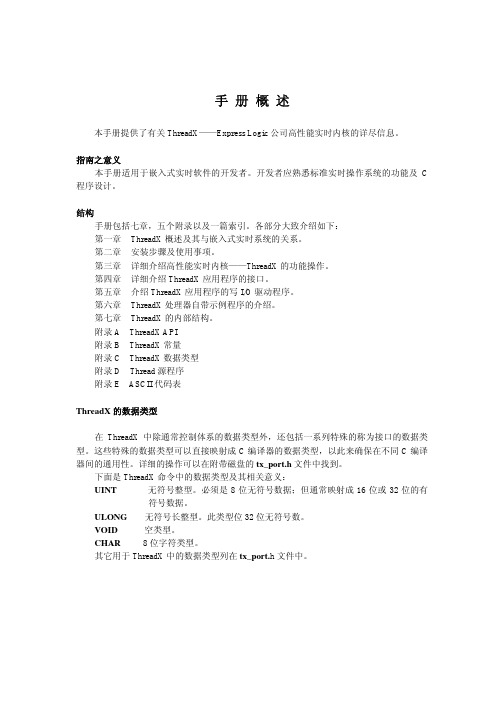
设置定时器中断周期为10ms
在此输入期望的中断周期10ms 这里列出了当前选择的定时器能 够实现的定时周期及精度 设此处限定定时误差,若设置的中断周 期超出此误差,则处理器专家会报错
CodeWarrior 10.6 IDE使用手册
CodeWarrior 10.6 IDE使用手册
3
利用工程向导快速创建KEA工程
e.选择编程语言和浮点数支持以及控制 台(console)硬件支持: f.选择是否使用处理器专家系统以及工 程外设driver的使用模式:
CodeWarrior 10.6 IDE使用手册
4
利用工程向导快速创建KEA工程
其中包含了默认看门狗、SWD调试口以及Flash Memory 的设置
在CPU组件的属性设置中还包括CPU 内核中断/复位设置(CPU interrupt/reset)
其中包含了CPU内核系统级中断(ARM Cortex M0+实现的 异常):不可屏蔽中断NMI、硬件错误异常Hard fault(当 CPU执行非法指令、非对其地址访问时触发该异常,可以 用于捕获程序跑飞时的场景)、超级调用Supervisor Call和 可请求服务异常(用于RTOS系统任务切换),以及内部时 钟失锁(ICS Loss of lock)。所有这些中断的优先级都高于 外设中断。
CodeWarrior 10.6 IDE使用手册
18
添加和配置定时器中断组件
最后在中断回调函数中添加中断处理,这里为全局中断计数器加1; 注意:用户的中断处理代码必须加在处理器专家指定的位置
CodeWarrior 10.6 IDE使用手册
compareC 包的中文名字:比较两个相关的 C 指数与右侧定时器生存结果的包说明书

浅谈中学历史课的教学人们常说:教历史是最容易的,讲故事一样。
其实历史的教学并不象他们说的那么轻松,要想上好一堂历史课,达到预期的效果,还真要讲究一些方法和艺术。
也有不少学生认为:历史是死的,背一背就成了。
其实正如学生所言:历史是死的,也正因为如此,历史的教学也非容易之事,它和其它的课程不同,如语文着重于感情的朗读,数学着重于数字的运用,物理、化学则着重于实验等等。
而历史的教学却是比较枯燥的,因为我们所要讲述的都是过去了的事,是死板的。
所以要讲好历史课,使学生有兴趣听和学,从而提高教学质量。
这就要求我们多寻找一些方法,多讲究一些艺术。
对此,我有如下的一些体会:一、更新观念。
把学生作为学习的主人,让学生动起来,让课堂活起来。
努力改变教师满堂灌,牵着学生走,学生被动学,围着教师转的现象。
二、充分发扬教学民主,注重学生的人格培养,努力形成新型的平等、和谐的师生关系。
古人曰:“亲其师,信其道”,它深刻而精辟地点明了和谐、融洽的师生关系在教学活动中的重要作用;苏联教育家霍姆林斯基也曾经这样认为,“师生之间是一种互相有好感、互相尊重的和谐关系,这将有利于教学任务的完成”。
由此可见,良好的师生关系是提高教育质量的关键之一。
三、采用多种方式方法,激发学生的兴趣。
学生对学习有无兴趣,既是反映学生学习效率的重要标志,也是衡量教师教学成败的重要因素。
如何增强课堂教学的趣味性,激发学生学习的兴趣,使学生的学习变被动为主动,从而提高教学质量,方式方法是多种多样的。
1、利用导语,激发兴趣:导语能够承上启下,开宗明义,如同舞台上缓缓拉开的大幕,让学生一眼就能看到的精美的布景;又如乐章的序曲,使学生一开始就受到强烈的感染。
2、渗透时事,增加兴趣:历史与时事密不可分,脱离现实的历史教学是没有意义的。
历史教师必须关注时事,在历史教学中渗透时事,让学生意识到历史与现实不远。
3、创设情景,感受兴趣:初中学生形象思维强,抽象思维弱,对于久远的历史难以感知,教师可以借用图片和影视创设丰富的情景,把抽象的历史概念变成学生可以感知的历史形象,把逝去的历史真实生动地再现在学生的面前,从而缩短时空距离,使学生的情感受到感染,思想受到启迪。
TASKING 251 USB 快速入门说明书

WelcomeWelcome to the TASKING software evaluation tools for the 251 and 8x930 USB. The evaluation softwareconsists of EDE, our MS-Windows based Embedded Development Environment, editor, the Power C compiler,assembler, linker/locator, and the CrossView Pro simulator and ROM monitor debugger. You can get up and running with the tools very quickly by following the Quick Start instructions below. The software can be used for any member of the 251 family, including the 8x930 USB peripheral controller. You will be able to compile,assemble and link programs, produce ROMable code and run it on CrossView Pro. In order to use CrossView Pro ROM, you will need a target board running the RISM ROM monitor. All Intel boards come with RISM inside an EPROM. TASKING has ported RISM to the Temic and Keil board. Preconfigured examples are delivered for:SimulatorDemo C programc:\d251\examples\demo\sim.pjt Intel 8x930 USB Evaluation BoardDemo C program c:\d251\examples\demo\usb.pjt Intel 151/251 Evaluation BoardDemo C program c:\d251\examples\demo\rism.pjt Intel 251 ProjectBuilder Board (old)Demo C program c:\d251\examples\demo\rismpb.pjt Temic 251A1/G1 Evaluation BoardDemo C program c:\d251\examples\demo\ri_temic.pjt Keil MCB251 Evaluation BoardDemo C program c:\d251\examples\demo\ri_temic.pjt SimulatorSieve C benchmark c:\d251\examples\sieve\sieve.pjt Simulator Assembly program c:\d251\examples\asm\asm.pjtTable-1 Example ProjectsRestrictionsThe editor is a demo version and the compiler and assemblersupport a limited number of symbols and operands. The linkerallows up to 3K of code size. CrossView also has some restrictionsincluding the About box popping up every 5 minutes. Please refer tothe Demo Limits help file for more details. Although theserestrictions do apply, we believe that the demo package is adequatefor you to be able to make a purchasing decision.InstallationStart MS-Windows. Insert the 251/USB demo CD-ROM. ForWindows 3.1x, in the Program Manager select the File|Run...menu item. For Windows 95, press the Start button and select theRun... menu item. In the dialog box type D :\SETUP (where D: isthe drive letter of your CD-ROM player) and follow the instructionson the screen. At the end of the installation procedure a ProgramGroup window will show up on the screen of your computer. It willlook like the one shown in figure-1. You will use the EDE icon themost, since it presents you with a complete environment from whereyou can invoke the manuals and the other tools.NOTE: When using Windows 95 you can create a shortcut onyour desktop by dragging the EDE icon to the desktop using theright mouse button!Figure 1 Program GroupStarting EDEEDE is a standard Windows application which you can launch either by double-clicking the EDE icon in the Program Group, or via the Start Menu when using Windows 95. Please note that the EDE on-line manual also contains an extensive Getting Started with EDE chapter.EDE OverviewEDE is an integrated embedded software development environment that combines a powerful editor withproject management and an automated make facility. After you invoke the EDE, the window shown in figure-2will show up on your screen.From this environment you can create and maintain projects, edit files, specify tool options, compile, assemble and link your application, access on-line manuals and invoke the CrossView Pro debugger environment.Project ManagementEDE is more than a language sensitive editor. It is a completeproject environment which gives you direct access to the toolsand features you need to be your most productive. EDE lets youdefine the files of your project and, by navigating through thetabs, select the tool options that apply. With the EDE projectmanager you create and maintain a project so your application isalways up-to-date. All aspects of a project are saved in theproject file: the source files that make up the application, the tooloptions (compiler, assembler, linker and CrossView Prodebugger), the tool directories and the options describing thebuilding process. The project manager handles file dependenciesas well as the exact sequence of operations required to buildyour application.There are a number of example demo project files included in thepackage, as listed in table-1 on page 1. By rebuilding aCrossView Pro demo you can verify the proper installation of thesoftware and confirm that you can compile, assemble, link anddebug an application. This tutorial will build the demo Capplication for the 8x930 USB evaluation board, but the steps arequite similar for the other execution environments. To switchfrom the simulator execution environment, which is the defaultproject of the demo, to the 8x930 USB board, select USB.PJTfrom the Projectmenu.Figure 2 Embedded Development EnvironmentFigure 3 Project MenuSetting Processor OptionsYou can now edit the files belonging to the project. The filesDEMO.C and ADD251.SRC are automatically opened. To seewhich files belong to the project, select the Project|LoadFiles... menu item. The next step is to specify the options forthe Processor and the different parts of the toolchain.The Processor Options allow you tochoose the execution mode of the CPU:binary mode or source mode. Please notethat the factory setting of most boardsassumes binary mode. So you eitherhave to rebuild the application for binarymode (select Binary Mode and click OK)or set the board to run in source mode(DIP switch MOD0 must be set to ‘on’for Source Mode, ‘off’ for Binary Mode).In the Memory tab of the ProcessorOptions you specify how the CPU isconfigured with regards to internalROM/RAM as well as the externalmemory interface (RD# and PSEN#functions). For the 8x930 USB board, theUSB controller is a ROM-less part andhas 1K of internal RAM. The externalmemory interface is configured for using18 address lines (A0-A17), so the CPUaddresses 256KB as one linear spacefrom 0-3FFFFH. In the Linker Optionsyou can now specify the external ROMand RAM areas within the 256KB range.NOTE: When changing anyprocessor option the assembly systemstartup code (LIB\START.SRC) must bepart of your project!Figure 4 EDE OptionsFigure 5 CPU Execution ModeFigure 6 CPU Memory SettingsSetting Development Tool OptionsYou can now specify the compiler and assembler options for your project. For example, the memory model to be used and which optimizations must apply. The compiler and assembler option selection responds to the active window. If the active window in EDE is e.g. a C source file, the compiler selection in the EDE menu allows you to set options for that specific file or for all the C files in the project. The order in which you do so is not important. Individual file options always prevail over project wide options. Every time you close the option selection from the EDE menu a new build file (makefile) is generated.There is also a Memory tab inside theLinker Options dialog. This tab is veryimportant, since here you specify whereyour external ROM and RAM areas are,which memory areas must be reservedand more. Figure 7 shows the settings forthe 8x930 USB evaluation board.The 8x930 USB board has 128KB ofRAM for downloading application codeand data. The upper 128 KB of memory isnot used, except for the 32K EPROMwhere RISM resides. RISM expects theapplication and it’s interrupt vectors tobe located at 4000H. In this example wehave specified RAM in the lower 16KBand the rest of the memory (112K) to beused for downloading user code andconstant data. When using RISM youmust reserve memory from 20H to 3FH,since the ROM monitor uses this area.For the same reason, the system startupcode must start to clear internal RAM at 40H (instead of 8H). For the 8x930 USB board the linker/locator must also map all the segments of type CODE (8051 compatible 64KB code area) to page 0 (0-0FFFFH) instead of page 0FFH (0FF0000H-0FFFFFFH), since RISM expects the user code to start in page 0. The last item to take care of is the reset vector. RISM assumes the application’s reset vector is at 4000H instead of 0FF0000H, so you must specify this to the linker/locator.Building the ApplicationThe next step is to compile and link the files in your project and build theprogram so you can debug the application. First save any edited files andthen click on the ‘Rebuild’ button in the toolbar. EDE compiles and links yourproject and creates an absolute object module called USB.ABS , ready fordebugging.The building process is logged in the Output Window. If error messages occur, there is a button to browse through a list of error messages.When you use the 'ERR' button the editor prompts you automatically to the right position in the source file where the error has been detected.You can inspect the resulting map file by opening USB.MAP in theeditor (File|Open…)Figure 7 Memory Settings for the 8x930 USB boardFigure 8 RebuildFigure 9 Error MessagesDebugging the Application with CrossView ProIn order to simulate code execution or download code to the evaluation board, you need to invoke the CrossView Pro debugging environment. Before launching CrossView Pro you need to select the execution environment: either the simulator or the ROM monitor. For the ROM monitor version you have to connect the evaluation board to your PC and specify additional communications parameters. Select the EDE|CrossView Pro Options... menu item in order to invoke the CrossView Pro Options dialog.Connect the 8x930 USB evaluation board to the correct COM port of your PC and power on the board. Specify a baudrate of 19200 when using the external serial port (UART), 9600 when using the internal serial port. After having pressed the OK button, you can launch the CrossView debugger by clicking on the ‘Debug’ (fly-swatter) button in the toolbar.Loading the ApplicationCrossView Pro has now already loaded the application and downloaded the image to the board. Select the File|Load Application menu item in order to invoke the Load Application dialog. In this dialog youcan specify an ‘Automatic Start’, ‘Target reset’ and ‘Goto main’ for subsequent debugging sessions.Figure 10 CrossView Pro OptionsFigure 11 Load ApplicationStepping ThroughNow click on Run in the menu bar and select Program Reset . This resets the software and the board and may take a few seconds. The reset empties the Source Window when it is in source display mode. At the reset address there is only startup code that does not relate to C-source. One program step (Step button in the toolbar) causes the program to execute the C-startup code, enter the main()function and fills the Source Window.Using the toolbar or the menu bar you can edit breakpoints, watch data, display the stack, simulate I/O and much more. Please note that all the User Manuals are available as help files with hypertext links for easynavigation and the EDE manual has an extensive Getting Started with EDE chapter guiding you through the process of creating a new project.Questions or Problems?Depending on where you are located call one of the following numbers and tell customer support that you are using the 251/8x930 USB demo version 2.0.USA:1-800-458-8276,fax7813209212,e-mail:**********************Europe:+31334558584,fax+31334551005,e-mail:**********************Japan:+81334576831,fax+81334576834,e-mail:******************.jp See us also at: Figure 12 CrossView Pro Desktop。
新人必看 单片机定时器应用实例解析

新人必看单片机定时器应用实例解析
对于刚开始接触单片机定时器知识学习的新人工程师来说,牢固巩固知识基础只是迈出的第一步,更重要的是要结合单片机的设计实例,灵活利用单片机定时器来完成相关的程序设计。
在今天的文章中,我们将会通过一个实际案例,来为大家解析一下单片机定时器在实际应用中的一些设计步骤和技巧。
在本案例中,我们所提出的条件是利用单片机定时器定时50毫秒,使用定时器0,工作方式1模式。
50毫秒一到,即点亮指示灯D1。
按照这一设计要求,我们可以按照下列两个大步骤来进行单片机程序的设置。
我们要做的第一个步骤就是确定定时器0初始化程序。
这一部分的设计是非常重要的,按照单片机的正常使用程序,我们可以从四个方面出发,来进行相应的设置。
第一步是要完成对TMOD的赋值设置,以此来确定T0和T1的工作方式。
在本案例中,我们已经从前文所提及的设计要求上明确了这一方案中需要使用定时器0工作方式,因此这一步的工作就简单了很多。
此时,
TMOD=0X01,因此设置定时器0为工作方式1。
具体设置过程在一些单片机基础教程上已经讲解的非常叙述,因此在本案例的设计过程中,我们不再做过多的赘述。
在完成了对单片机定时器的对TMOD的赋值设置之后,接下来的工作就是精确计算计数初值X,并在得出相应数值后将其按照要求写入TH0、TL0,或写入TH1、TL1。
在本案例中,由于晶振给出的条件为12MHz,所以我们所选取的机器周期Tcy为1ms。
因此,定时器要计数50000个就是50毫秒,。
基尔斯特 5015a 电荷计用户手册说明书

Page 1/6Electronics & SoftwareCharge MeterUniversally Applicable for Piezoelectric Measuring Technology5015A _000-297e -01.21© 2010 ... 2021 Kistler Group, Eulachstrasse 22, 8408 Winterthur, Switzerland . Kistler Group products are This information corresponds to the current state of knowledge. Kistler reservesthe right to make technical changes. Liability for consequential damage resulting Type 5015A...This instrument can be used wherever mechanical quantities are measured with piezoelectric sensors. Piezoelectric sensors produce an electric charge which varies in direct proportion to the load acting on the sensor.• Single-channel charge amplifier • Piezotron input (option)• Measure-jump compensated• Liquid crystal display (128x128 pixels)• Menu-driven operation • Direct signal evaluation• Flexible adjustment of high-pass and low-pass filters • Compatible with Charge Amplifier Type 5011B...• PC-Software and Virtual Instrument Driver for LabVIEW DescriptionThe Type 5015A… is not only a charge amplifier but an uni-versal Charge Meter with a graphical liquid crystal display. However, the 19"-r ack module is also suitable for measurements in an industrial environment. It can display instantaneous, peak and average values as well as reference deviations. State-of-the art technology allows the naturally occurring interference to be almost entirely eliminated. The instrument is distinguished first-ly by its excellent technical data and secondly by its extremely simple operation.ApplicationThe instrument has been designed for use in research, devel-opment and the laboratory.OperationPage 2/65015A _000-297e -01.21© 2010 ... 2021 Kistler Group, Eulachstrasse 22, 8408 Winterthur, Switzerland Tel.+41522241111,****************,. Kistler Group products are This information corresponds to the current state of knowledge. Kistler reserves the right to make technical changes. Liability for consequential damage resulting Drift, meas. mode voltage DC (long) (@ Range 10 V FS; Gain = 1) at 25 °C, max. relative mV/s <±0,03 humidity RH of 60 % (non-condensing)at 50 °C, max. relative mV/s <±0,3 humidity RH of 50 % (non-condensing)Max. common mode voltage V <±30 between input and output ground Overload %F S ≈±105Piezotron mode Supply current mA 4 ±10 % Input voltage swing V 0 (20)Voltage Output Connector Type BNC neg.Output range FS V ±10/±5/±2,5/±2Output current mA <±2Output impedance Ω ≈10Measure-jump Compensated Measure-jump (Long) mV <±3 Correction time, inclusive reed-relay delay time ms <15 1)Zero errors mV <±2Output interference (0,1 Hz ... 1 MHz), Type 5015Axxx0 Range FS, LP filter off 2,000 ... 9,999 pC mVpp <140 ... <40 10,00 ... 99,99 pC mVpp <30 ... <10 1) 100,0 ... 999,9 pC mVpp <15 ... <7 1) ... mVpp <15 ... <7 1) 0,220 ... 2,200 µC mVpp <15 ... <7 1) Range FS, LP filter 30 kHz 2,000 ... 9,999 pC mVpp <60 ... <20 10,00 ... 99,99 pC mVpp <20 ... <7 1) ... mVpp <10 ... <5 1) 0,220 ... 2,200 µC mVpp <10 ... <5 1)Output interference (0,1 Hz ... 1 MHz), Type 5015Axxx1 Range FS, LP filter off 2,000 ... 9,999 pC, mV mVpp <220 ... <50 10,00 ... 99,99 pC, mV mVpp <50 ... <12 1) 100,0 ... 999,9 pC, mV mVpp <20 ... <7 1) ... mVpp <20 ... <7 1) 0,220 ... 2,200 µC mVpp <20 ... <7 1) Range FS, LP filter 30 kHz 2,000 ... 9,999 pC, mV mVpp <180 ... <50 1) 10,00 ... 99,99 pC, mV mVpp <30 ... <10 1) 100,0 ... 999,9 pC, mV mVpp <10 ... <5 1) ... mVpp <10 ... <5 1) 0,220 ... 2,200 µC mVpp <10 ... <5 1) 1)Values valid from MCC version V2.xxFrequency Response DC (Long), LP-filter off Bandwidth (–3 dB) kHz ≈0 ... 200 Group delay µs ≈10High-pass Filter (1st order)Analog high-pass filter DC (Long)Range FS Charge, (Voltage) 2 pC, (mV) s 10 000 1 000 pC, (mV) s 100 000Time constants Medium s 1/10/100/220 Short s 0,1/1/10/220Tolerance % <±20Digital high-pass filter computed by DSPTime constantsRange FS Charge, (Voltage) 2 pC, (mV) s 0,01/0,1/1 100 pC, (mV) s 0,01/0,1/1/10 ≥1 000 pC, (mV) s 0,01/0,1/1/10/100Tolerance % <±20Cutoff frequencies –3 dB Hz 16/1,6/0,16/0,016/ 0,0016 –10 % Hz 30/3/0,3/0,03/0,003 –5 % Hz 50/5/0,5/0,05/0,005 –1 % Hz 100/10/1/0,1/0,01Low-pass FilterDigital low-pass filter computed by DSP Filter Type IIR, linear phase Order 2. or 5.Cutoff frequency (–3 dB) Hz 5, 10, 20, 30, 50, 100, 200, 300, 500 kHz 1, 2, 3, 5, 10, 20, 22, 30, (LP off)Tolerance % <±10Page 3/65015A _000-297e -01.21© 2010 ... 2021 Kistler Group, Eulachstrasse 22, 8408 Winterthur, Switzerland Tel.+41522241111,****************,. Kistler Group products are This information corresponds to the current state of knowledge. Kistler reserves the right to make technical changes. Liability for consequential damage resulting Signal Evaluation Sample rates LP-filter on ksps 400 LP-filter offksps 1 000Minimum pulse width for peak-peak value detection LP-filter 5 Hz ... 30 Hz µs >2 500 LP-filter 50 Hz ... 300 Hz µs >250 LP-filter 500 Hz ... 3 kHz µs >25 LP-filter 5 kHz ... 30 kHz µs >2,5 LP-filter offµs >1Max. integration time for mean value min <75Integration time for the updating rate of the liquid crystal display Instant value ms 300 Characteristic values ms 300 Bar graph ms 17,5Remote Control Connector Type MiniDin round socked Pin allocationInputs with internal pull-up resistor Pin 4 (input) Window (remote) Pin 5 (input) Measure (remote) Pin 6 DGND Input voltagelogic inactive or input open V 3,5 ... 30 logic active V(mA) 0 ... 1 (0 ... 4)Delay timeWindow (remote) ms <0,5 Measure (remote) ms <15Digital Measuring Data TransferThe instrument provides a continuos measuring data transfer via the serial interface to a PC. For this the PC software (Windows) of the VI driver (LabVIEW) is required. This feature is not available on the IEEE-488 interface. Sampling rates ksps0,1/0,25/0,5RS-232C Interface (Electrically Separated)EIA-standard RS-232C Connector Type DB-9S (D-Sub)Pin allocation Pin 2 RxD Pin 3 TxD Pin 5 SG Max. cable length at 9 600 bps m <15 19 200 bps m <15 38 400 bps m <12 57 600 bps m <10 115 200 bps m <5Max. input voltage,continues V <±20Max. voltage between signal ground and protective ground V RMS <20Baud rates bps 1 200/9 600/ 19 200/38 400/ 57 600/115 200Data-bit 8Stop-bit 1Parity none SW handshake noneIEEE-488 Interface (Option)Standard IEEE-488.1-1987 Connector Type Microribbon series 57 (24-pole)Max. distance between devices m 2Max. bus length m 20Max. number of devices 15Adress range 0 ... 30Functions Listener and Talker Interface functions SH1, AH1, L4, LE0, T6, TE0, SR1, RL2, PP0,DC1, DT1, C0, E1Multiline commands DCL, SDC, GET, UNL, UNT, SPE, SPD Uniline commands IFC, REN, EOI, SRQ, ATNPage 4/65015A _000-297e -01.21© 2010 ... 2021 Kistler Group, Eulachstrasse 22, 8408 Winterthur, Switzerland Tel.+41522241111,****************,. Kistler Group products are This information corresponds to the current state of knowledge. Kistler reserves the right to make technical changes. Liability for consequential damage resultingPower Supply ConnectionPower plug (2P+E, protect. class I) IEC 320C14Supply voltage setable V~ 115/230Supply voltage tolerance % –22, +15Supply frequency Hz 48 ... 62Consumption VA ≈20Voltage between Signal ground and protective ground V RMS <50FusesF1 (slow) mA 100 F2 (slow) mA 100Remaining DataIP-Degree of protection IP40, IEC 60529Operating temperature °C 0 ... 50Storage temperature °C –10 (70)Rel. humidity, not condensing %10 (80)Vibration steadiness(20 Hz ... 2 kHz, duration 16 min, cycle 2 min.) g <10Shock steadiness (1 ms) g <200Housing dimensions with frame (wxhxd) mm 105,3x142x253,15 without frame (wxhxd) mm71,12x128,7x230Front panel (accordingDIN 41494, part 5/IEC 60297) HE/TE 3/14Weightkg ≈2,3Fig. 1: Block Diagram of charge meter Type 5015A…Page 5/65015A _000-297e -01.21© 2010 ... 2021 Kistler Group, Eulachstrasse 22, 8408 Winterthur, Switzerland Tel.+41522241111,****************,. Kistler Group products are This information corresponds to the current state of knowledge. Kistler reserves the right to make technical changes. Liability for consequential damage resultingFig. 2: Desktop Type 5015A1… (stackable)Fig. 3:19"-Rack plug-in Type 5015A0…Page 6/65015A _000-297e -01.21© 2010 ... 2021 Kistler Group, Eulachstrasse 22, 8408 Winterthur, Switzerland Tel.+41522241111,****************,. Kistler Group products are This information corresponds to the current state of knowledge. Kistler reserves the right to make technical changes. Liability for consequential damage resulting Included AccessoriesCharge Meter Type 5015A... with • Country-specific power cord • Plug for 'Remote Control'• Self-adhesive label with supply voltage details • Flash-Loader with current firmware• Demo-Program for visualization of the display on a PC • PC-Software and VI-Driver for LabVIEW for the equip-ment configuration and measured data acquisition • Instruction manual • Calibration sheetOptional Accessories Type/Art. No.• RS-232C cable, l = 5 m, null-modem, 1200A27 DB-9P/DB-9S• or PC-link cable RS-232C, l = 3 m, 1465A3 DB-25P/DB-9S• with suitable D-Sub adapter , 1479 DB-9P/DB-25SInstrument ConfigurationsThe complete type designation of the Charge Meter is made up of the basic type designation Type 5015A... and four ad-ditional digits.The basic type contains a single-channel Charge Meter (with charge input for piezoelectric sensors) with display unit and RS-232C interface in the following versions:Ordering Key Type 5015ASize/Measuring Range19" rack module version according to 0 DIN 41494; width 14 TE and height 3 HE Desktop version with support bracket 1Without interface option0With IEEE-488 interface (option) 1Adjusted in the factory to 230 V~; 0switching to 115 V~supply by the user possible at any time Adjusted in the factory to 115 V~; 1switching to 115 V~supply by the user possible at any time Without voltage input0With voltage input for sensors with 1integrated Piezotron circuitry (option)Windows is a registered trademark of Microsoft bVIEW is a registered trademark of National Instruments Corporation.。
ThreadXUserGuide-中文手册
常只要几个礼拜的时间。
非黑盒结构 ThreadX 的大部分包括完全的 C 源代码,这排除了许多商业性的内核结构所存在的“黑 盒”问题。在使用 ThreadX 时,程序开发者可以清楚的看到内核运行细节,不存在什么秘 密。 源代码还允许开发程序过程中特殊的修改。虽然没有介绍,但在十分必要时有能力去 修改内核是很有用的。 这些特色对那些习惯于用自己内部内核的开发者来说应该是特别另人振奋的。他们期 望得到源代码并且能够修改内核。ThreadX 对这些人来说是最合适的内核了。
■ 嵌入式应用程序 实时软件 多任务 任务及线程
■ ThreadX 的优点 改进的响应特性 软件维护 增强的吞吐量 处理器隔离 程序划分 好用性 提高开发时间 保护软件投资
ThreadX 概 述
ThreadX 概述
ThreadX 是专为嵌入式应用而设计的高性能实时内核。同其它实时内核不同,ThreadX 具有通用性,使基于 RISC(reduced instruction set computer 简化指令集计算机)和 DSP(Digital Signal Processing 数字信号处理)的小型微控制器的应用程序易于升级。
手册概述
本手册提供了有关 ThreadX——Express Logic 公司高性能实时内核的详尽信息。
指南之意义 本手册适用于嵌入式实时软件的开发者。开发者应熟悉标准实时操作系统的功能及 C
程序设计。
结构 手册包括七章,五个附录以及一篇索引。各部分大致介绍如下: 第一章 ThreadX 概述及其与嵌入式实时系统的关系。 第二章 安装步骤及使用事项。 第三章 详细介绍高性能实时内核——ThreadX 的功能操作。 第四章 详细介绍 ThreadX 应用程序的接口。 第五章 介绍 ThreadX 应用程序的写 I/O 驱动程序。 第六章 ThreadX 处理器自带示例程序的介绍。 第七章 ThreadX 的内部结构。 附录 A ThreadX API 附录 B ThreadX 常量 附录 C ThreadX 数据类型 附录 D Thread 源程序 附录 E ASCII 代码表
LTE定时器详解
T300:该定时器由系统消息SIB2下发(参见36.3315.2.2.9),值存在名为UE-TimersAndConstants的信息块中(IE),当UE的上层要求处于RRC_IDLE 状态的UE发起RRC连接请求时,T300开始启动。
值得一提的是,当连接态下(RRC_Connected),SIB2消息下发后,存贮于该消息块中其他的定时器及常量是不做更新的,但是T300需要进行同步更新。
当收到了RRC连接建立,RRC 连接拒绝,小区重选或者高层主动释放连接时,该定时器终止。
除了正常RRC 连接建立导致T300的终止,其他原因导致T300终止后,MAC层相关配置都需要进行重置并释放掉。
小区重选和高层还需要RLC层重建。
如该定时器超时,则会重置MAC层,释放掉MAC配置以及重建RBs(Radio Bears)已有的RLC 实体。
3GPP协议中规定T300的取值范围为枚举值,分别可以为{ms100,ms200,ms300,ms400,ms600,ms1000,ms1500,ms2000}, 其中ms100代表定时器时长可以设为100毫秒。
该定时器设置的长短决定了网络中RRC连接建立的成功率以及资源的合理利用情况,如果设置过长,可以提升RRC连接建立成功率,但是可能会导致无谓的消耗资源,例如在小区覆盖边缘地区或者高干扰区域,信号质量已经恶化的情况下,层三信令并不释放连接,而是等待底层进行不断的重传尝试,这样不仅导致个体用户接续时延的增加,可能还会带来对网络资源整体的消耗以及导致的拥塞发生,同时还可能由于底层不断的重传导致网络干扰的抬升。
反之,如果该定时器设置过短,可能导致RRC连接建立成功率过低,从而进一步影响CS域或者PS域业务接通率。
在无线网络优化中,设置参数的目的不是为了单纯的提升统计KPI,而是在适配网络结构的基础上,使得KPI尽量贴近用户感知,既不能恶化KPI使用户感知受到影响,也不能单纯的提升了某项KPI,而使得其与用户感知完全脱节,最佳合理的策略是正向同步优化KPI作为评估手段的基础上,提升用户感知。
定时器50us初值
定时器50us初值1. 任务背景介绍定时器是嵌入式系统中常用的一个功能模块,用于产生精确的时间延迟或周期性的定时触发。
定时器的初值决定了定时器的计数周期,而定时器的计数速度则由系统时钟频率决定。
本文将介绍如何设置一个定时器的初值为50us,以及相关的编程方法和应用场景。
2. 定时器的工作原理定时器的工作原理可以简单概括为以下几个步骤:1.设置定时器的计数器初值。
2.启动定时器开始计数。
3.当计数器达到设定的初值时,触发定时器中断或执行相关操作。
4.重置计数器,继续循环计数。
定时器的计数速度由系统时钟频率决定,通常以Hz(赫兹)为单位表示。
计数器初值和计数速度的关系决定了定时器的定时周期。
3. 设置定时器初值为50us的方法要设置定时器的初值为50us,首先需要知道系统时钟频率。
假设系统时钟频率为f,那么定时器的计数速度就是fHz。
定时器的计数周期为1/f秒。
为了设置定时器的初值为50us,可以按照以下步骤进行操作:1.计算50us对应的计数周期数。
设定计数周期为T,那么50us对应的计数周期数为50us/T。
2.根据计数周期数,设置定时器的初值为50us。
具体的设置方法可能因不同的嵌入式系统和编程语言而有所不同,下面以C语言为例,介绍一种常见的设置方法。
// 设置定时器初值为50us的函数void set_timer_initial_value(uint32_t system_clock_frequency, uint32_t timer_f requency) {uint32_t timer_initial_value = (system_clock_frequency / timer_frequency)* 50 / 1000000;// 设置定时器初值timer_set_initial_value(timer_initial_value);}在上述代码中,system_clock_frequency表示系统时钟频率,timer_frequency表示定时器的计数频率。
H3C-R多功能模拟计时器说明书
t
t-a
t
t-a t-a
t
Output mode E : Interval(1A1C)
t
Rt
t
SOURCE (2-7)
N.C. (8-5)
N.O. (8-6) Output LED
N.C. (1-4)
N.O. (1-3)
Power LED
Rt t - a
Set time = t , t - a < t , Reset time = Rt
N.C. (11-8)
N.O. (11-9) Output LED
N.C. (1-4)
N.O. (1-3)
Power LED
t
t-a
t-a
t
0.5s
0.5s
DIMENSIONS : (mm)
N type(Surface Mounting): Using P2CF-08 , PF085A Socket or PF113A Socket(for H3C-R11 use only)
N.O. (1-3, 8-6) Output LED
Power LED
Set time = t , t - a < t , Reset time = Rt
Rt t - a
t
SOURCE (2-10)
Start signal (2-6)
Reset (2-7)
N.C. (1-4, 11-8)
N.O. (1-3, 11-9) Output LED Power LED
Ambient humidity MAX 85%RH
Weight
Approx. 100g
TYPE SELECTION :
技能认证AFC专业考试(习题卷6)
技能认证AFC专业考试(习题卷6)第1部分:单项选择题,共47题,每题只有一个正确答案,多选或少选均不得分。
1.[单选题]服务器不能开启的故障处理登记要求A)需高级工以上或者指导下完成B)至少线路负责人与维修人员双人确认C)高级工,至少一名技术主办或技师以上级别技术专工,双人确认D)没要求答案:C解析:2.[单选题]如果没有安装________,TCM将不能分析单程票?A)羊城通SAMB)新地铁SAMC)手机SAMD)旧地铁SAM答案:B解析:3.[单选题]因违规操作或设备技术状态不良造成票务收益流失或损失,合计价值10万元以上属于________。
A)一类票务事故B)二类票务事故C)三类票务事故D)四类票务事故答案:C解析:4.[单选题]紧急情况下(如洪灾、火灾等自然灾害)站厅AFC设备关机步骤( )。
①短按工控机开关以关闭工控机(如无法远程关闭)②断开站厅电源切换箱的AFC设备漏电保护空开③通过综合监控工作站/维修工作站远程关闭站厅所有设备④关闭UPS主机,断开电源模块空开A)③②①④B)①②④③C)①②③④D)③①②④答案:A解析:5.[单选题]环网冗余是一种以太网高速冗余技术。
此项技术不仅能够保证网络在遇到故障时(同一环网协议),通讯能在( )内恢复,还可以在环网链接断开时通过出错继电器、指示灯或SNMP发出警报。
A)100msB)200msC)300msD)400ms答案:CA)计价参数B)设备控制参数C)运营点参数D)运营控制参数答案:D解析:7.[单选题]若白色报警栏突然消失,采用以下()命令可以重新开启,且不会被关闭。
A)warnB)warn&C)WARN&D)Warn&答案:D解析:8.[单选题]在客户端用PLSQL软件连接Oracle数据库时,必须先配置服务器数据库的( )。
A)环境变量B)监听程序C)主机IP地址D)本地Net服务名答案:B解析:9.[单选题]以下对MEI纸币机描述正确的是________。
- 1、下载文档前请自行甄别文档内容的完整性,平台不提供额外的编辑、内容补充、找答案等附加服务。
- 2、"仅部分预览"的文档,不可在线预览部分如存在完整性等问题,可反馈申请退款(可完整预览的文档不适用该条件!)。
- 3、如文档侵犯您的权益,请联系客服反馈,我们会尽快为您处理(人工客服工作时间:9:00-18:30)。
1#include<stc5201.h>
2#include<intrins.H>
3
4sbit COM1 = P2^0;
5sbit COM2 = P2^1;
6sbit COM3 = P2^2;
7sbit COM4 = P2^3;
8sbit inputpin = P2^5;
9sbit FOUT = P2^4; //用于Timer0输出方波
10unsigned char
ledtab[]={0xed,0x09,0xe3,0xab,0x0f,0xae,0xee,0x89,0xef,0xaf};
11
12unsigned char thou,hund,ten,one;
13int count_key;
14void HEX_TO_BCD(int mun);
15
16//定时器0初始化函数,欲启用定时器功能时被调用
17//TMOD用法:前4bit管timer1, 后4比特管timer0
18//bit 7 6 5 4 3 2 1 0
19//Name GATE C/!T M1 M0 GATE C/!T M1 M0
20void TIMER0_init(void)
21{
22 TMOD =0x11;
23 ET0 =1; //打开Timer0中断功能, ET0=0是关闭中断功能
24 TR0 =1; //Timer0启动
25 EA =1;
26}
27
28// 定时器0中断服务程序,注意主函数里没有主动调用,
29// 此函数是自动执行 (当条件满足时即Timer0溢出从0xffff->0)
30void timer0_INT_SRV(void) interrupt 1
31{
32 TL0 = (65536-50000)%256;
33 TH0 = (65536-50000)/256; /* Set Timer0 50ms INT at 12.000MHz
std 51*/
34 count_key++;
35 HEX_TO_BCD(count_key);
36 FOUT =!FOUT;
37}
38
39//外中断初始化函数,在用中断功能时被调用
40void EXT0_int_init(void)
41{
42 EX0 =1; //打开外中断0功能, EX0=0是关闭中断功能
43 IT0 =1; //INT0引脚下降沿触发中断,IT0=0是低电平触发中断
44 EA =1; //所有中断的总开关,0是关
45}
46
47// 外中断0服务程序,注意主函数里没有主动调用,
48// 此函数是自动执行 (当条件满足时即INT0/P3.2有下跳沿)
49void EXT0_int_SRV(void) interrupt 0
50{
51 count_key++;
52 HEX_TO_BCD(count_key);
53}
54
55void delayms(int ms)
56//这个软件大约可以等待ms毫秒
57{
58int i,k;
59for(k=0; k<ms;k++) { for(i=0;i<500;i++); }
60}
61
62void refresh(void)
63{
64 P1 = ledtab[thou];//thousand
65 COM4=0;
66 delayms(4);//大约等4ms
67 COM4=1;
68
69 P1 = ledtab[hund];
70 COM3=0;
71 delayms(4);
72 COM3=1;
73
74 P1 = ledtab[ten];
75 COM2=0;
76 delayms(4);
77 COM2=1;
78
79 P1 = ledtab[one];
80 COM1=0;
81 delayms(4);
82 COM1=1;
83}
84
85void HEX_TO_BCD(int num)
86{
87 thou = num/1000;
88 hund = num/100%10;
89 ten = num%100/10;
90 one = num%10;
91}
92
93void function(void)
94{
95 count_key++;
96 HEX_TO_BCD(count_key);
97}
98
99/*-------------------------------------------
100Port Output Configuration Settings FOR STC
101PxM1.y PxM0.y Port Pin Mode for STC
102 0 0 Quasi-bidirectional开机默认状态
103 0 1 Push-Pull 高低电平强力输出,也叫推挽输出104 1 0 Input Only (High Impedance)
105 1 1 Open Drain
106此软件用芯片STC5204AD
107--------------------------------------------*/
108void main(void)
109{
110 P1M1 =0x00; //这两句把P1口的所有8个IO脚设置成推挽输出111 P1M0 =0xff;
112
113//EXT0_int_init(); //外中断0打开了
114 TIMER0_init(); //定时器0中断打开,同时启动了定时器0 115
116while(1)
117 {
118 inputpin=1;//a
119if(inputpin==0)
120 {
121 delayms(20); // 步骤b
122if(inputpin==0) // c 再次确认
123 {
124 function(); // 执行该按钮的指令集合125while(inputpin==0)
126 {
127 refresh();
128 } //等待释放时不忘记继续刷新显示器129 }
130 }
131
132 refresh(); //不管有没有按钮动作都执行的工作133
134 }
135}
136//所有有人机交互有外界输入的软件结构就是这个套路
137。