暖通空调设计工具箱
暖通空调系统设计手册完整版

暖通空调系统设计手册目录第一章设计参考规范及标准................................................. 错误!未定义书签。
一、通用设计规范:...................................................... 错误!未定义书签。
二、专用设计规范:...................................................... 错误!未定义书签。
三、专用设计标准图集:.................................................. 错误!未定义书签。
第二章设计参数. (5)一、商业和公共建筑物的空调设计参数ASHRAE (5)二、舒适空调之室内设计参数日本 (6)三、新风量 (7)1、每人的新风标准ASHRAE (7)2、最小新风量和推荐新风量UK (8)3、各类建筑物的换气次数UK (8)4、各场所每小时换气次数 (9)5、每人的新风标准UK (10)6、考虑节能的基本新风量(1/s人)(日本) (10)7、办公室环境卫生标准日本 (11)8、民用建筑最小新风量 (11)第三章空调负荷计算 (14)一、不同窗面积下,冷负荷之分布% (14)二、负荷指标(估算)(仅供参考) (14)三、空调冷负荷法估算冷指标。
空调冷负荷法估算冷指标(W/M2空调面积)见下表 (15)四、按建筑面积冷指标进行估算建筑面积冷指标 (16)五、建筑物冷负荷概算指标香港 (17)六、各类建筑物锅炉负荷估算W/M3℃ (19)七、热损失概算W/M3℃ (19)八、冷库冷负荷概算指标 (19)第四章风管系统设计 (21)一、通风管道流量阻力表 (21)1、缩伸软管摩擦阻力表 (21)2、镀锌板风管摩擦阻力表 (21)二、室内送回风口尺寸表 (24)1、风口风量冷量对应表 (24)2、不同送风方式的风量指标和室内平均流速ASHRAE (24)三、室内风管风速选择表 (25)1、低速风管系统的推荐和最大流速m/s (25)2、低速风管系统的最大允许速m/s (25)3、通风系统之流速m/s (26)四、室内风口风速选择表 (26)1、送风口风速 (26)2、以噪音标准控制的允许送风流速m/s (26)3、推荐的送风口流速m/s (27)4、送风口之最大允许流速m/s (27)5、回风口风速 (27)6、回风格栅的推荐流速m/s (28)7、百叶窗的推荐流速m/s (28)8、逗留区流速与人体感觉的关系 (28)9、顶棚散流器送风量 (28)10、侧送风口送风量 (29)五、通风系统设计 (31)1、送风口布置间距 (31)2、标准型号风盘所接散流器的尺寸表-办公室 (31)3、散流器布置 (31)4、空调房间允许最大送风温差℃ (32)5、工艺性空气调节空调房间允许最大送风温差. (32)6、厨房通风问题 (32)7、消声器、静压箱总结 (36)8.风管贴吸音材料风道的衰减量(日本) (37)9.风管的自然衰减量(只有直风道dB/m,其它都是dB) (38)六、防排烟设计 (38)第五章管道系统设计 (42)一、空调管路系统的设计原则 (42)二、管路系统的管材 (43)三、供回水总管上的旁通阀与压差旁通阀的选择 (44)四、空调水系统管径的确定 (45)五、冷冻水泵扬程估算方法 (47)1、水泵扬程简易估算法 (47)2、冷冻水泵扬程实用估算方法 (48)3、水泵扬程设计 (49)六、冷却水系统的设计 (49)1、冷却水系统的补水量 (50)2、冷却水循环系统设计中应注意的几个问题: (50)七、冷凝水管道设计 (51)八、分汽缸、分水器、集水器尺寸的确定 (52)九、膨胀水箱的容积计算 (54)十、空压管道管径选择表 (56)十一、保温 (57)十三、阀门选用 (58)第六章空调设备选型 (59)一、机组选型 (59)二、机组选型案例 (59)三、辅助设备 (60)1、冷却塔 (60)2、水泵的选型: (60)3、热泵中央空调系统水量计算 (61)4、冷冻水和冷却水流量估算 (62)5、设备水压力降估算(日本) (62)6、制冷机冷却水量估算表 (63)第七章材料、设备资料 (63)一、钢板和铝板的厚度和重量ASHRAE (63)二、角钢和角铝的规格和重量ASHRAE (63)三、计算单位换算 (64)四、常用液体的密度(单位:103千克/米3,未注明者为常温下) (66)五、空气调节常用计算公式 (67)六、钢材理论重量计算 (69)七、专业英语 (70)第八章耗电量、机房面积 (82)1、水源热泵系统设备耗电量比例 (82)2、医院耗电量比例TRANE (82)3、各种系统分项造价占总造价的百分率%(近似) (82)4、冷水机组和附属设备估算(△T=5℃) (82)5、空调面积占建筑面积比例 (83)6、空调机房建筑面积概算指标 (83)7、空调设备所占的建筑面积百分率% (84)8、设备层布置原则: (85)第九章暖通空调中存在的问题及解决办法、图纸要求 (86)一、贯彻执行暖通设计规范、标准方面存在的问题 (86)1.1室内外空气计算参数不符合规范要求 (86)1.2供暖热负荷计算有漏项和错项 (86)1.3卫生间散热器型式选择不妥 (86)1.4楼梯间散热器立、支管未单独配置 (86)1.5供暖管道敷设坡度不符合规范要求 (86)1.6厨房操作间通风存在问题 (86)1.7膨胀水箱与热(冷)水系统的连接不符合规范要求 (87)1.8通风空调系统防火阀的设置不符合规范要求 (87)1.9防烟楼梯间前室送风口风量的确定有问题 (87)1.10误将防烟分区排风量的计算混同于排烟风机风量的计算 (87)1.11高层建筑排烟系统排烟口选型不当 (88)二、在工程设计中存在的问题 (88)2.1供暖入口设置过多 (88)2.2供暖系统设计不合理 (88)2.3排风系统设计不合理 (88)2.4空调系统的选择不合理 (88)2.5厕所采用风机盘管时未加新风 (89)2.6平衡阀的设置与口径选择存在问题 (89)2.7 系统分区不当造成失败 (89)2.8、双风机系统设计问题 (90)2.9 送回风管布置不好 (91)3.0 排气系统设计诸问题 (92)三、设计图纸方面存在的问题 (93)3.1设计说明内容不完整 (93)3.2平面图深度不够,有些应该绘制的内容遗漏 (93)3.3系统图深度不够 (94)3.4锅炉房设计过于简化 (94)3.5计算书内容不全甚至全部空白 (94)3.6暖通空调设备未编号列表表示,图画繁杂不清 (94)3.7平面图、剖面图、系统图不一致 (94)3.8设计图纸与计算书不一致 (94)四、问题原因及克服方法 (95)五、施工图设计深度要求 (95)5.1 设计说明、施工说明、图例和设备表 (95)5.2 设备平面图 (95)5.3 剖面图 (96)5.4 通风、空调、制冷机房平面图 (96)5.5 通风、空调、制冷机房剖面图 (96)5.6 暖通设计中的系统图、立管图 (96)5.7 详图 (96)计算书(供内部使用,备查)............................................ 错误!未定义书签。
手术室暖通空调设计优化(包含品牌、产品名、型号)说明书

OPERATINGROOM HVAC DESIGN OPTIMIZATION OF THE MODERN O.R.TABLE OF CONTENTSExecutive Summary ....................................................................................................................................3Introduction ................................................................................................................................................4What to look forRoom Type/Name ..................................................................................................................................4Single Plane vs Biplane & Floor Mounted vs Ceiling Mounted Imaging Equipment .....................................5Medical Equipment Manufacturer ............................................................................................................5Design Parameters and ConsiderationsAirflow Requirements..............................................................................................................................6Strut Channel and Medical Equipment Support Rails ...............................................................................6ASHRAE 170 Table Coverage .................................................................................................................6Creating the Ideal OR Ceiling System Layout ...........................................................................................7OptimizationEngineered Ceiling Grid ..........................................................................................................................8Common Plenum System .......................................................................................................................8Fully Integrated Common Plenum and LED Lighting System .....................................................................8Conclusion . (8)2For more information visit | v001OPERATING ROOM HVAC DESIGNOptimization of the Modern O.R.A traditional OR (Figure 1) allows for a large diffuser array directly above the operating table. It is typically easy to meet ASHRAE 170 criteria when designing a ventilation and ceiling system for a traditional OR. The Hybrid OR (Figure 2) utilizes monitors and imaging equipment which consume valuable ceiling space and complicate the design process. Modern operating rooms require an engineered solution, often with custom diffusers and ceiling grids in order to maintain accessibility and cleanability of laminar flow diffusers while meeting FGI guidelines and ASHRAE 170 requirements.Through our development of innovative HVAC solutions,Price Industries is meeting the challenge of the modern operating room head on. Whether a project requires a fully customized common plenum diffuser system with integrated LED lighting (Ultrasuite) or individually ducted HEPA diffuser modules in a welded ceiling grid (HGWC), Price Industries has a fully customized solution for each challenge. Our design engineers take pride in creating innovative solutions that are aesthetically pleasing and meet your performance requirements.Figure 1: Traditional Operating RoomFigure 2: Hybrid Operating RoomEXECUTIVE SUMMARYDue to the ever-increasing demand for valuable ceiling space, modern operating room (OR) ceiling and air distribution systems must continuously improve and adapt to meet the demands presented by ceiling mounted medical equipment.Conventional hospital operating room design utilizes a unidirectional, non-aspirating ventilation system which creates a particulate free zone at, and directly adjacent to, the patient table. This document will provide direction on how to maintain a particulate free zone around the patient and surgical team within the constraints of the complex medical imagery equipment that is an inherent feature of the modern OR.3v001 | For more information visit OPERATING ROOM HVAC DESIGNOptimization of the Modern O.R.INTRODUCTIONThe modern operating room, including hybrid operating rooms and imaging suites, requires more complex ceiling and HVAC solutions compared to traditional operating rooms. This document will outline what to look for, how to design, and how to optimize a modern OR HVAC design project.A hybrid operating room, as defined by the FGI Guideline for Design and Construction of Hospitals, is “a room that meets the definition of an operating room and is also equipped to enable diagnostic imaging before, during, and after surgical procedures. Imaging equipment is permanently installed in the room and may include M RI, fixed single-plane and bi-plane tomographic imaging systems, and computed tomography equipment.” Whether or not a space is designated as a Hybrid OR, Electrophysiology (EP) Lab,Catheterization (Cath) Lab, or Interventional Radiology (IR) Lab, it typically requires the same considerations to determine feasibility of an engineered integrated ceiling and air distribution system.A traditional OR layout with 2 ft. x 2 ft. or 2 ft. x 4 ft. diffusers and lights is unlikely to offer the best solution for a modern OR that utilizes imaging equipment and ceiling mounted monitors. Custom sized diffusers are often required to provide enough laminar airflow directly above the operating table while maintaining internal diffuser access and cleanability. Identifying and locating both ceiling level strut channel and imaging equipment support rails below the ceiling is a critical first step when designing a modern OR ceiling layout.Figure 3: Custom OR ceiling system, featuring the Price Ultrasuite4For more information visit | v001OPERATING ROOM HVAC DESIGNOptimization of the Modern O.R.WHAT TO LOOK FORRoom Type/NameThe room type/name is typically the first indication that a space will require a custom diffuser layout. The following room types generally require ceiling level strut channel to support tomographic imaging systems, monitors, radiation shields, etc.: +Hybrid OR+Electrophysiology (EP) Lab +Catheterization (Cath) Lab +Interventional Radiology (IR) LabWhile plans for the room types mentioned above may not show any medical equipment in their preliminary stages. There is still a very good chance that ceiling level strut channel will be required for these applications and the engineered ceiling system will have to be coordinated around it.Single Plane vs. Biplane, & Floor Mounted vs. Ceiling Mounted Imaging EquipmentNot all Hybrid ORs and Imaging Suites utilize ceiling level tomographic equipment or require ceiling level strut channel to support medical equipment. A small portion of Hybrid ORs and Imaging suites, typically single plane, can utilize traditional OR diffuser layouts.A single plane imaging suite utilizes one C arm which can be floor mounted and can be used without installing equipment support rails from the ceiling which limit diffuser placement. Single plane imaging suites may still utilize ceiling mounted monitors and/or radiation shields which are typically supported from ceiling level strut channel.A biplane imaging suite utilizes two C arms along with monitors and/or radiation shields and almost always require ceiling level support strut to supportthe equipment.Figure 4: Single plane imaging suiteFigure 5: Biplane imaging suite5v001 | For more information visit OPERATING ROOM HVAC DESIGNOptimization of the Modern O.R.Medical Equipment ManufacturerThere are many medical equipment manufacturers that each require unique ceiling level strut channel layouts to support their equipment. The images below reflect strut channel and equipment layouts for the most common medical imaging equipment suppliers. The uniqueness of each strut channel layout shows the importance ofcoordinating an engineered HVAC and ceiling system around each specific medical equipment supplier.Figure 6: Strut channel layouts for common medical equipment6For more information visit | v001OPERATING ROOM HVAC DESIGNOptimization of the Modern O.R.DESIGN PARAMETERS AND CONSIDERATIONSAirflow RequirementsAs with any OR design, the first step is to identify airflow requirements for the space based on the design criteria set out in ASHRAE 170-2017 Standard for the Ventilation of Health Care Facilities and/or applicable local codes. The following considerations should be taken: +Design for a positively pressured room with aminimum of 20 total air changes per hour (ACH) +Unidirectional downwards MERV 14 (or HEPA)filtered airflow with an average velocity of 25 to 35 cfm/sq.ft.+ A primary supply diffuser array, of which nomore than 30% is used for non diffuser uses, that extends a minimum of 12 in. beyond the footprint of the operating tableCombining these design parameters greatly reduces the risk of infection during medical procedures by creating a sterile field around the patient and medical team.Strut Channel and Medical Equipment Support Railsthe number of diffusers required to meet code has been determined, they must be located and placed within the ceiling level strut channel and medical equipment support rails. Figure 8 is an example of an imagingsuite ceiling layout where the vertical rails reflect ceiling level strut channel. Diffusers cannot physically be placed in these locations. Most medical equipment suppliers specify strut channel located on 26” centers which allows standard width diffusers to be used. The horizontal lines reflect medical equipment support rails which install directly below the ceiling. Diffusers can be placed in these locations but the faces cannot be opened for internal access or cleaning once the rails are installed so avoiding these locations is stronglyrecommended as well.ASHRAE 170 Table CoverageThe image below illustrates how a central row of custom size laminar flow diffusers can be sized to create a sterile field of MERV 14 (or HEPA) filtered air around the surgical area.Figure 7: Imaging suite ceiling level strut channel and medical equipment support rail schematicFigure 8: Custom diffuser schematic7v001 | For more information visit OPERATING ROOM HVAC DESIGNOptimization of the Modern O.R.Creating the Ideal ORCeiling System LayoutWhile a common 2 ft. x 2 ft. or 2 ft. x 4 ft. laminar flow diffuser layout (figure 9) will meet all ASHRAE 170 requirements, the diffusers may not fit into the structural support for the medical imaging equipment. Additionally, diffuser faces may not be removable once the medical equipment rails and equipment is installed which nullifies the functionality of the ¼ hardware and the cleanability of the laminar flow diffuser itself. Layouts such as figure 10 which account for ceilinglevel strut channel but not the medical equipment railswill still pose challenges regarding the functionality andcleanability of the laminar flow diffusers.sized laminar flow diffusers (figure 11) is the best wayto ensure that ASHRAE 170 requirements are metwhile maintaining all laminar flow diffuser functionality.Figure 9: Layout meets ASHRAE 170 requirements but isincompatible with strut channelFigure 11: Custom diffuser layout meets ASHRAE 170 standards and coordinates with medical equipmentFigure 10: Layout meets ASHRAE 170 requirements but isincompatible with equipment rails8For more information visit | v001 OPERATING ROOM HVAC DESIGNOptimization of the Modern O.R.OPTIMIZATIONPrice Industries offers many opportunities to optimize a modern OR ceiling layout.Engineered Ceiling GridDrywall framing around each individual diffuser and light fixture is a common installation method in a standard OR. A Hybrid OR installation has additional challenges in that drywall framing is also required around ceiling level strut channel. A best-case laminar flow layout design in a hybrid operating room typically has 25-30% of the 12” operating table extension used for non-diffuser uses and the added framing required for each diffuser is often enough to push that number over the 30% threshold and eliminate ASHRAE 170 compliance. A Price HGWC welded ceiling grid integrates directly with ceiling level strut channel and ensures maximum coverage of the 12” operating table extension.Common Plenum SystemThe additional structure present in a Hybrid OR creates coordination challenges for ductwork. A Price HGP common plenum laminar flow system has all the benefits of a HGWC welded ceiling grid while reducing the overall ductwork requirement to as little as two inlet connections or less for an entire operating suite.Fully Integrated Common Plenum and LED Lighting SystemFurther optimization can be found with a Price Ultrasuite common plenum system with integrated LED lighting which provides high quality LED lighting directly over the operating table while providing all of the benefits of a common plenum laminar flow system.Figure 13: Hospital-Grade Common Plenum (HGP)Figure 12: Hospital-Grade Welded Ceiling System (HGWC)Figure 14: OR Diffuser System with Integrated LEDLighting (Ultrasuite)9v001 | For more information visit OPERATING ROOM HVAC DESIGNOptimization of the Modern O.R.CONCLUSIONDesigning an HVAC system and ceiling grid for a modern operating room presents many challenges. Creating and maintaining a particulate free zone around the surgical area, which is critical in reducing surgical site infections, is further complicated by the imaging and diagnostic equipment that is present. Price Industries has the products and expertise to fit any application and overcome any challenges. Contact our application engineering team at **************************************** for comprehensive layout and design assistance.Figure 15: Hybrid OR featuring the Price Hospital Grade Common Plenum10For more information visit | v001OPERATING ROOM HVAC DESIGNOptimization of the Modern O.R.Product Improvement is a continuing endeavour at Price. Therefore, specifications are subject to change without notice. Consult your Price Sales Representative for current specifications or more detailed information. Not all products may be available in all geographic areas. All goods described in this document are warranted as described in the Limited Warranty shown at . The complete Price product catalog can be viewed online at .® Price is a registered trademark of Price Industries Limited. © 2023. Printed in Canada. v200。
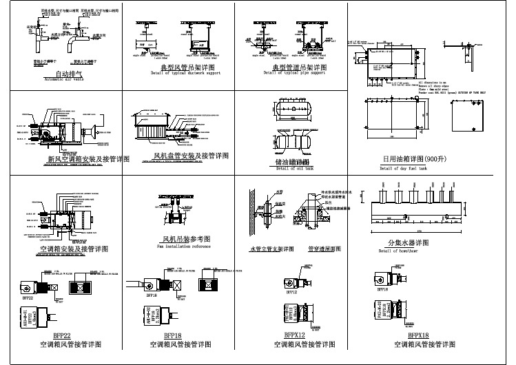
暖通各设备安装CAD详图
暖通空调实用工具箱
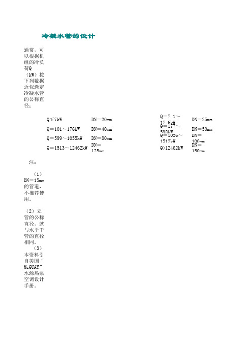
冷凝水管的设计通常,可以根据机组的冷负荷Q(kW)按下列数据近似选定冷凝水管的公称直径;Q≤7kW DN=20mm Q=7.1~17.6kW DN=25mmQ=101~176kW DN=40mm Q=177~598kW DN=50mmQ=599~1055kW DN=80mm Q=1056~1512kWDN=100mmQ=1513~12462kW DN=125mm Q>12462kW DN=150mm注:(1)DN=15mm的管道,不推荐使用。
(2)立管的公称直径,就与水平干管的直径相同。
(3)本资料引自美国“McQUAY”水源热泵空调设计手册。
风机盘管机组、整体式空调器、组合式空调机组等运行过程中产生的冷凝水,必须及时予沿水流方向,水平管道应保持不小于千分之一的坡度;且不允许有积水部位。
当冷凝水盘位于机组负压区段时,凝水盘的出水口处必须设置水封,水封的高度应比凝水盘处的负压(为了防止冷凝水管道表面产生结露,必须进行防结露验算。
注:(1)采用聚氯乙烯塑料管时,一般可以不必进行防结露的保温和隔汽处理。
(2)采用镀锌钢管时,一般应进行结露验算,通常应设置保温层。
冷凝水立管的顶部,应设计通向大气的透气管。
设计和布置冷凝水管路时,必须认真考虑定期冲洗的可能性,并应设计安排必要的设施。
冷凝水管的公称直径DN(mm),应根据通过冷凝水的流量计算确定。
一般情况下,每1kW冷负荷每1h约产生0.4kg左右冷凝水;在潜热负荷较高的场合,每1kW冷负荷每1h约产0mmDN=150mm水,必须及时予以排走。
排放冷凝水管道的设计,应注意以下事项:的高度应比凝水盘处的负压(相当于水柱温度)大50%左右。
水封的出口,应与大气相通。
排必要的设施。
的场合,每1kW冷负荷每1h约产生0.8kg冷凝水。
暖通空调课程设计说明书
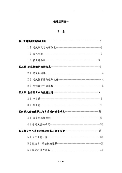
暖通空调设计目录第一章建筑概况与原始资料------------------------------------------2 1.1 建筑概况与地理位置-----------------------------------2 1.2 大气参数---------------------------------------------2 1.3 室设计参数-----------------------------------------3第二章建筑物维护结构信息--------------------------------------4 2.1 建筑物墙体------------------------------------------- 4 2.2 建筑物窗体与遮阳设施--------------------------------- 4 2.3 空调设计中的参数------------------------------------- 5 第三章负荷计算以与数据汇总-----------------------------------53.1 冷负荷---------------------------------------------- 6 3.2 热负荷----------------------------------------------20 第四章风盘的选择以与各房间的风盘确定--------------------------324.1 风盘的选择原则--------------------------------------32 4.2房间风盘的确定---------------------------------------32 第五章全空气系统的负荷计算与设备布置--------------------------335.1大厅负荷计算---------------------------------------- 33 5.2散流器、风柜机的选择----------------------------------38 5.3风管的水力计算---------------------------------------405.4大厅风机盘管的选型-----------------------------------42 参考文献------------------------------------------------------43第一章建筑概况与原始资料1.1.1建筑概况本建筑为tangshan市一幢餐厅、宴会厅和宾馆宾于一体的洗浴中心。
[资料]
![[资料]](https://img.taocdn.com/s3/m/b5844424915f804d2b16c157.png)
计算软件 供水热力计算器 计算软件 水管道阻力计算软件 计算软件 常用暖通计算工具 计算软件 翅片管重量计算软件 计算软件 [软件]空气物性计算 计算软件 [软件]实用计算工具 计算软件 暖通常用小软件 计算软件 地暖地板表面平均温度计算程序 计算软件 采暖系统水力计算软件 计算软件 板式换热器计算软件 计算软件 [软件]水力阻力 计算软件 空气状态点参数计算软件 计算软件 空气参数计算软件 计算软件 钢材重量计算工具 计算软件 [软件]风管风速快速选择计算 计算软件 工程专用计算器 计算软件 水管水力计算软件 计算软件 金属材料重量计算软件 计算软件 [软件]地暖设计计算 计算软件 [软件]水管、风管沿程阻力计算程序 计算软件 [软件]风管风速快速选择计算 计算软件 [软件]保温算量 计算软件 [软件]展开面积计算 计算软件 热工小计算软件
软件使用文档 CFD商业软件介绍及病房通风应用一例 软件使用文档 光洋KOYOPLC操作手册 软件使用文档 SATA驱动的后安装 软件使用文档 光绘工艺的一般流程 软件使用文档 AutoCAD小技巧 软件使用文档 Airpak 2.0 Tutorial Guide 软件使用文档 手绘采暖系统图教程(视频) 软件使用文档 鸿业6.0命令集 软件使用文档 鸿业5.2命令集 软件使用文档 各流体计算软件介绍 计算表格 [经典推荐]暖通工程设计计算必备的110个 excle表(含400多个工作表)
计算软件 蒸发器、冷凝器计算 计算软件 冷热负荷及空气处理计算 计算软件 地板采暖计算程序 计算软件 板式换热器设计计算软件 计算软件 暖气片水平串联计算软件 计算软件 空调水管保温层厚度(防结露)计算软件 计算软件 管道刷油面积及保温量计算软件 计算软件 空调冷负荷计算软件 计算软件 冷冻(却)系统流量计算 计算软件 空调水管比摩阻计算软件 计算软件 压缩机热力计算程序 计算软件 蒸汽管径计算软件 计算软件 风管内风速与风阻计算 计算软件 风管阻力计算软件 计算软件 水平串联采暖系统散热器片数量计算 计算软件 热水采暖管径计算软件 选型软件 水泵选型实用软件 选型软件 中央空调设计选型计算表 选型软件 风管水管末端计算软件 选型软件 焊接材料选型软件 选型软件 风管选型软件 选型软件 风管快速选取 选型软件 散热器选型软件 选型软件 风管快速格 洁净空调负荷计算表格 计算表格 风口布置设计计算表 计算表格 插值法公式表格 计算表格 空调消防送排风风管面积及支吊架法兰计 算软件
空调维修所需工具目录
空调维修所需工具目录
1. 螺丝刀
- 用途:拆卸和安装空调外壳、调整控制面板等
- 规格:平头螺丝刀、十字螺丝刀
2. 扳手
- 用途:拆卸和安装紧固件、调整管道连接等
- 规格:可调节扳手、定值扳手
3. 钳子
- 用途:拆卸和安装管道、连接器等
- 规格:长钳子、弯头钳子、尖嘴钳
4. 温度计
- 用途:测量空调系统的温度
- 规格:数字温度计、红外线温度计
5. 眼镜和手套
- 用途:保护眼睛和手部免受受伤和化学物品的伤害
6. 清洁工具
- 用途:清洁空调内部和外部部件
- 包括:刷子、吸尘器、清洁剂等
7. 真空泵
- 用途:抽取空调系统中的空气和湿气
- 规格:单级或双级真空泵
8. 加注工具
- 用途:加注制冷剂到空调系统
- 规格:加注管、压力表等
9. 电压表
- 用途:检测空调系统的电压和电流
- 规格:数字电压表、模拟电压表
10. 绝缘带
- 用途:绝缘电线和电缆,防止电击和短路
以上是进行空调维修所需的工具目录,根据实际情况和需要,工具的种类和规格可能会有所变化。
在进行维修工作时,请确保根据相关安全操作规程和法律法规进行操作。
★广东省院暖通技术标准
目录第一章空调设计制制图标准 (1)1.1空调设计电子文件管理及作图细则 (1)1.2空调CAD设置及插件管理 (3)1.3空调图纸目录编制及内容划分 (5)1.4空调专业项目设计控制流程 (6)第二章主要技术措施 (8)2.1负荷计算参数及I-D图绘制细则 (8)2.2主机、冷却塔选型、地下车库风机选型及主要设备提电原则 (9)2.3地下室通风设计细则 (10)2.4仓库等功能用房设计细则 (13)2.5电影院空调通风系统设计细则 (13)2.6厨房空调通风系统设计细则 (15)2.7互提资料书格式 (17)2.8酒店项目设计细则 (20)2.9多联机系统设计细则 (22)2.10商业消防排烟系统设计细则 (23)2.11住宅项目多联机冷量配置对比 (24)2.12办公项目标准层空调形式及层高、净高对比 (26)2.13商业项目层高、净高对比,冷指标对比 (27)第三章各类地产导则及项目资料 (29)3.1各类地产导则 (29)3.2项目资料 (29)3.3暖通计算书 (29)第一章空调设计制制图标准1.1空调设计电子文件管理及作图细则首先,各设计人员应熟读《暖通空调制图标准》GB/T50114-2010。
1.1.1文件名:建立子目录:项目名称(华润前海中心)子目录下宜对各类资料及图纸进行分类归档,建立多个文件夹,如下图:图纸归档名称统一采用图号+中文名称表示,该名称应简洁明了,也可以根据项目需要,增加前缀,如“KT1-1空调、通风施工图说明.dwg”。
如该电子文件由几张图合而为一,则可用“~”、“-”等表示,如“KT1-7a~c商业换热系统图a~c.dwg”。
原则上图纸文档应尽量是一对一关系。
1.1.2图纸规格:工程尽可能采用A1图幅,比例为1:100。
每项工程图幅建议不超过三种,作图比例:1:1001:1501:50比较大的图纸,作图比例亦可采用1:200。
1.1.3字体:电子文件中应尽量减少字体种类,结合表达的需要,按用途分为三个部分:用途字型名中西文字体文件名图名STANDARD 西文字体fszk.shx 中文字体gbhzfs.shx水平管标识STANDARD西文字体fszk.shx图标STANDARD 西文字体fszk.shx 中文字体gbhzfs.shx其它STANDARD 西文字体fszk.shx 中文字体hztxt.shx1.1.4文字规格:所有文字的宽高比均为0.7。
空调工程施工常用工具
安装使用的工具
三级配电箱(套)、照明灯(盏)、灭火器(个)、格力工作服、安全帽(顶)、安全带(套)、铜管和水管割刀(把)弯管器(套)、扩口器(套)、水平尺(把)、十字螺丝刀(套)一字螺丝刀(套)焊接工具(套)、力矩扳手(套)固定扳手(把)活动扳手(把)钳子(把)剪刀(把)氧气减压阀(块)氮气减压阀(块)乙炔减压阀(块)回火阀(个)双头压力表(块?)手电钻(把)拉钉枪(把)冲击电锤(把)
R410A多联机系统安装过程中与R22系统不能通用的安装工具仪器有:
润滑油:涂于纳子帽,润滑纳子帽表面。
应用有机合成油FVC68D,R22用矿物油SUNISO4GS,SUNISO4GS与R410A不相溶,混合后会出现油泥,可能发生循环阻塞。
制冷机灌(充注制冷剂)R410A为近共费混合型制冷剂,应确保在液态状态下充注。
真空泵及连接器:(抽真空)真空泵可以通用,但应接装用于防止真空泵停止时泵内矿物油倒流的连接器,即在吸气管上加装止回阀。
高低压压力表
充注导管
检漏仪
调试工具的准备
内六角扳手
活动扳手
十字螺丝刀、一字螺丝刀
风速仪、噪声仪、真空泵、电子秤、钳表,R410A制冷剂高低压力表。
某行政办公大楼风冷热泵系统设计图
- 1、下载文档前请自行甄别文档内容的完整性,平台不提供额外的编辑、内容补充、找答案等附加服务。
- 2、"仅部分预览"的文档,不可在线预览部分如存在完整性等问题,可反馈申请退款(可完整预览的文档不适用该条件!)。
- 3、如文档侵犯您的权益,请联系客服反馈,我们会尽快为您处理(人工客服工作时间:9:00-18:30)。
冷凝水管的设计
通常,可以根据机组的冷负荷Q(kW)按下列数据近似选定冷凝水管的公称直径;
Q≤7kW DN=20mm Q=7.1~17.6kW DN=25mm
Q=101~176kW DN=40mm Q=177~598kW DN=50mm
Q=599~1055kW DN=80mm Q=1056~1512kW
DN=100mm
Q=1513~12462kW DN=125mm Q>12462kW DN=150mm
注:
(1)DN=15mm的管道,不推荐使用。
(2)立管的公称直径,就与水平干管的直径相同。
(3)本资料引自美国“McQUAY”水源热泵空调设计手册。
风机盘管机组、整体式空调器、组合式空调机组等运行过程中产生的冷凝水,必须及时予
沿水流方向,水平管道应保持不小于千分之一的坡度;且不允许有积水部位。
当冷凝水盘位于机组负压区段时,凝水盘的出水口处必须设置水封,水封的高度应比凝水盘处的负压(为了防止冷凝水管道表面产生结露,必须进行防结露验算。
注:
(1)采用聚氯乙烯塑料管时,一般可以不必进行防结露的保温和隔汽处理。
(2)采用镀锌钢管时,一般应进行结露验算,通常应设置保温层。
冷凝水立管的顶部,应设计通向大气的透气管。
设计和布置冷凝水管路时,必须认真考虑定期冲洗的可能性,并应设计安排必要的设施。
冷凝水管的公称直径DN(mm),应根据通过冷凝水的流量计算确定。
一般情况下,每1kW冷负荷每1h约产生0.4kg左右冷凝水;在潜热负荷较高的场合,每1kW冷负荷每1h约产
0mm
DN=150mm
水,必须及时予以排走。
排放冷凝水管道的设计,应注意以下事项:
的高度应比凝水盘处的负压(相当于水柱温度)大50%左右。
水封的出口,应与大气相通。
排必要的设施。
的场合,每1kW冷负荷每1h约产生0.8kg冷凝水。