keyence三角尺
基恩士GV-21p说明书
基恩士GV-21p说明书keyence基恩士产品传感器①光电传感器:利用LED光源进行有无检测。
②光纤传感器:通过光纤提供高效高速的检测功能,适用于各种环境条件。
③激光传感器:使用可视聚焦激光光束,提供长距离有无检测功能。
④位移传感器:测量目标物体是否位于指定位置与公差。
可输入判断数据或测量值。
⑤图像识别传感器:超小体积可选,易于安装、可多点检测的视觉传感器。
具备自动对焦、彩色成像与长距离模式等特点。
⑦接近传感器:检测黑色金属和有色金属的有无⑧通信模块:通过EtherNet/IP?、DeviceNet?、EtherCAT或CC-bbbb网络,检测和控制传感器。
测量仪 / 测量传感器①激光位移传感器 (1D):单点激光三角传感器,可高速、正确、精确地测量距离与位置。
②激光轮廓测量仪 (2D):2D和3D激光扫描仪/分析器,用于测量高度、间距、面积、角度、半径、点到点、点到线等等。
③尺寸测量仪 / 外径测量仪:1D和2D激光扫描与光学测微计,可测量直径、螺距、齿宽角圆率、位置和半径。
④激光共焦位移测量仪:表面扫描激光共焦点位移传感器,采用2 μm 光束检测玻璃、镜像与多阶层目标。
⑤分光干涉式激光位移计:分光干涉位移计,φ2mm超小传感器头,不发热,无噪音, 5kHz采样频率,可以实现无时间误差的6点测量。
⑥涡电流式位移传感器:高速测量金属目标。
距离、偏转、厚度、定位与偏心率。
105℃耐热,适用于油污水分等恶劣环境。
⑦接触式传感器:高精度、高耐用度,检测分辨率高达0.1微米。
连接多个单元进行计算或比较。
测量系统①图像尺寸测量仪 IM 系列:兼具“超凡的测量速度”与“超高的测量精度”的图像尺寸测量仪I M 系列能让您的测量工作发生巨大变化。
②形状测量激光显微系统 VK-X 系列:非接触式3D测量系统,几乎可在任何材料上进行纳米级剖面、粗糙度与厚度测量。
③3D轮廓测量仪 VR-3000 系列:高精度非接触式面积分析仪,可在短短数秒之内获取到精确且可重复的大面积3D测量值。
基恩士旋转角度测量

基恩士旋转角度测量
基恩士旋转角度测量是一种非常重要的测量技术,它在工业、科研、航空航天等领域都有广泛的应用。
基恩士作为一家知名的测量设备制造商,其旋转角度测量产品具有高精度、高稳定性、高可靠性等特点,深受用户的信赖和好评。
旋转角度测量是指测量物体绕某一点旋转的角度,这个角度可以是绝对角度,也可以是相对角度。
在工业生产中,旋转角度测量通常用于监测机器设备的运行状态,比如测量旋转轴的转速、转向、转角等参数,从而确保设备的正常运转和产品质量的稳定。
在科研领域,旋转角度测量则常用于实验室中的精密测量和控制,如光学、机械、电子等领域的实验和研究。
基恩士的旋转角度测量产品采用了先进的测量原理和技术,能够实现高精度的角度测量。
其中,一些高端产品还具有自动校准、温度补偿、防震防干扰等功能,能够在各种复杂的环境下进行稳定的测量。
此外,基恩士的旋转角度测量产品还具有易于操作、维护方便等优点,使得用户能够轻松地完成测量任务,提高工作效率。
总之,基恩士旋转角度测量技术在工业、科研等领域中发挥着重要的作用,为各种应用提供了可靠、精确的角度测量解决方案。
随着科技的不断发展,基恩士将继续推出更加先进、更加智能的旋转角度测量产品,满足用户不断增长的需求,推动测量技术的不断进步和发展。
90度三角尺的公差

90度三角尺的公差什么是90度三角尺?90度三角尺是一种常见的测量工具,通常由透明的塑料或金属制成。
它的形状是一个直角三角形,其中一个角度是90度。
90度三角尺通常用于工程、建筑、数学和制图等领域的测量和绘图工作中。
公差的定义公差是指实际尺寸与标准尺寸之间允许的最大偏差范围。
在制造和测量过程中,公差十分重要,因为它决定了产品和测量工具的精度。
90度三角尺的公差意义在使用90度三角尺进行测量和绘图时,公差是决定其准确性和可靠性的关键因素之一。
如果90度三角尺的公差很大,可能导致测量结果和绘图误差较大,影响工作质量和准确性。
90度三角尺的测量公差90度三角尺的测量公差通常分为两个方面:角度公差和尺寸公差。
1.角度公差:90度三角尺的一个角度被定义为90度,所以角度公差应该在90度的允许范围内。
通常,角度的公差为±0.5度或更小。
这意味着当测量角度时,实际测量值应在90度的±0.5度内。
2.尺寸公差:90度三角尺的尺寸公差通常是指边长。
边长的公差可以根据不同的应用和制造方法而有所不同,一般在0.1毫米到0.5毫米之间。
这意味着边长的实际测量值应在标准尺寸的±0.1毫米到±0.5毫米范围内。
影响公差的因素90度三角尺的公差受到多种因素的影响,包括制造工艺、材料、测量方法等。
下面是几个影响公差的主要因素:1.制造工艺:90度三角尺的制造工艺和精度对公差有直接影响。
制造工艺越精密,公差范围越小,测量结果越准确。
2.材料选择:90度三角尺可以使用多种材料制造,如塑料、金属等。
不同材料的机械性能和热胀冷缩系数会影响公差范围。
3.测量方法:使用90度三角尺进行测量时的技术和方法也会影响公差。
正确的使用方法和精确的读数能够减小误差产生的可能性。
如何保证90度三角尺的公差符合要求为了确保90度三角尺的公差符合要求,有几个关键步骤和措施是必要的:1.选择合适的材料:选择合适的材料,能够满足规定的机械性能和热胀冷缩系数要求,以确保公差范围的稳定。
基恩士GT2_kc
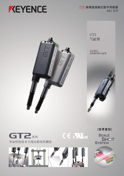
12 mm
测量范围
32 mm
12 mm
GT2-A12
GT2-A12K
高精度型
GT2-A32
通用型
精度 : 1 μm (p-p)
精度 : 3 μm (p-p)
精度 : 2 μm (p-p)
无需任何夹具。
由于传感头无需移动,因此无需安装复杂的夹具。 此外还消除了由于夹具而产生的精度错误。
安装简单快速。
无需分度夹具。
90° R
可以经受 2 千万次弯曲而不断裂
W
(“典型”使用情况下)
4
电缆可以在任何位置切割。 自由切割
容易的传感器头安装与设置
[安装/设置步骤数量减少]
使用专用支架轻松完成安装
传统方法
GT2
安装容易且简单, 只需钻一个 10 mm 的孔。
用户必须准备好钻有槽 子的夹具。
设置多个装置时,大指示灯可带来很大便利。
GT2 解决方案 轻松的方式:
显示器
模拟卡
PLC 编程
完成
完成
轻松的方式:
完成
按钮设置
HH、HI、GO、LO、LL 离散输出
“GT2 系列”具有 5 个数字比较器输出(HH、HI、GO、LO 以及 LL),只需几分钟而不是几小时就能完成设置。 此外还具有按钮校正功能,您不妨自问一下为什么还不赶快换用“GT2 系列”。
防尘套(替换用可选购附件)
外观
适用的传感器头 GT2-H12 GT2-H12K GT2-H32 GT2-H50
用于更大的目标
50 mm 范围
低压力型
分辨率 :0.5 μm 准确度 :3.5 μm (P-P)
通用型传感器头 GT2-H50 50 mm 范围传感器头不提供 低压力型。
服装工业非接触三维人体测量技术

服装工业非接触三维人体测量技术吴新侠【摘要】针对服装工业非接触三维人体测量技术,介绍了该技术各类测量方法的原理和特点,分析了各种方法的优点和存在问题,指出其面临的障碍.【期刊名称】《纺织科技进展》【年(卷),期】2010(000)002【总页数】4页(P85-87,98)【关键词】三维人体测量;非接触;服装工业;原理和特点【作者】吴新侠【作者单位】东华大学服装学院,上海,200051【正文语种】中文【中图分类】TS941.1人体测量不仅是正确建立服装原型的必要手段,也是服装工业化生产中制定号型规格标准的基础。
服装业传统的人体测量方法大都是手工测量或者凭经验观察,这种方法不仅测量数据少,不精确,而且测量时间长,使被测试者感觉疲劳和窘迫,所以无法满足服装制造的需要。
由于计算机视觉技术的兴起和发展,非接触式三维测量已成为现代人体测量技术的主要手段,与传统测量方法相比具有非接触,测量快速、准确,易于实现自动化等优点[1],并且它可以满足未来服装数字化设计、三维虚拟试衣、量身定制等要求。
因此,应用非接触三维测量已成为人体测量的发展趋势。
发达国家于20世纪70年代开始了三维人体自动测量在服装领域的应用研究,并开发出一些测量系统。
具有代表性的有美国纺织与服装技术中心的TC2分层轮廓测量系统、英国 Cyberware全身扫描仪及德国TechMath人体扫描系统等。
但是这些系统自身还存在一定问题,并且价格昂贵,与计算机接口复杂,不利于大范围推广使用[2]。
而我国在这方面的研究起步较晚,虽然积累了一定的经验并取得一定的成果,但与实际生产仍存在很大差距。
目前国内对三维人体测量的研究大多在采用国外系统的基础上研究后期数据的处理和模块的建立,很少有对三维人体测量的前期技术做研究,并且存在着对测量方法分类不清晰、原理混淆等问题。
本文介绍各种非接触三维人体测量方法的原理及特点,为国内服装业三维人体测量技术的发展和完善提供必要的信息。
KEYENCE温度传感器工作原理和挑选方法

KEYENCE温度传感器工作原理和挑选方法KEYENCE温度传感器工作原理和挑选方法KEYENCE温度传感器金属在环境温度变化后会产生一个相应的延伸,因此传感器可以以不同方式对这种反应进行信号转换。
KEYENCE温度传感器两片不同膨胀系数的金属贴在一起而组成,随着温度变化,材料A比另外一种金属膨胀程度要高,引起金属片弯曲。
弯曲的曲率可以转换成一个输出信号。
双金属杆和金属管传感器随着温度升高,金属管(材料A)长度增加,而不膨胀钢杆(金属B)的长度并不增加,这样由于位置的改变,金属管的线性膨胀就可以进行传递。
反过来,这种线性膨胀可以转换成一个输出信号。
热电偶由两个不同材料的金属线组成,在末端焊接在一起。
再测出不加热部位的环境温度,就可以准确知道加热点的温度。
由于它必须有两种不同材质的导体,所以称之为热电偶。
不同材质做出的热电偶使用于不同的温度范围,它们的灵敏度也各不相同。
热电偶的灵敏度是指加热点温度变化1℃时,输出电位差的变化量。
对于大多数金属材料支撑的热电偶而言,这个数值大约在5~40微伏/℃之间。
由于热电偶温度传感器的灵敏度与材料的粗细无关,用非常细的材料也能够做成温度传感器。
也由于制作热电偶的金属材料具有很好的延展性,这种细微的测温元件有的响应速度,可以测量快速变化的过程。
如果要进行可靠的温度测量,首先就需要选择正确的温度仪表,也就是温度传感器。
其中热电偶、热敏电阻、铂电阻(RTD)和温度IC都是测试中的温度传感器。
以下是对热电偶和热敏电阻两种温度仪表的特点介绍。
1、热电偶热电偶是温度测量中的温度传感器。
其主要好处是宽温度范围和适应各种大气环境,而且结实、价低,无需供电,也是的。
热电偶由在一端连接的两条不同金属线(金属A和金属B)构成,当热电偶一端受热时,热电偶电路中就有电势差。
可用测量的电势差来计算温度。
不过,电压和温度间是非线性关系,温度由于电压和温度是非线性关系,因此需要为参考温度(Tref)作第二次测量,并利用测试设备软件或硬件在仪器内部处理电压-温度变换,以最终获得热偶温度(Tx)。
KEYENCE XM系列手持探头坐标测量机的产品介绍说明书
Handheld Probe CoordinateMeasuring MachineXM SeriesEasy, on-site measurements by anyoneBENCH-TOP COORDINATE MEASURING MACHINEMeasurement when you need it, where you need it YOUR PERSONAL COORDINATE MEASURING MACHINE123453ALL-IN-ONE CONCEPTOn-sitemeasurementsHANDHELD PROBEEasy to handle with no restrictionsPROBE CAMERASee what you measureX θ STAGEEasy operationSIMPLE INTERFACEEasy to understandBench-top coordinate measuoffering on-site measuremenimmediately after power-upThe XM Series features immediate launch cappower supply. Achieve high-precision coordinatesacrificing space. When it comes to meeting suchimmediate measurement and reductions in measualso improving productivity, KEYENCE’s XM Seriesmeasuring machine is the answer.Ultra-robust camera15" LCD monitorStage marker4*For XM-1200 and XM-T1200 models. XM-1000 and XM-T1000 models feature a fixed stage.5Position detection technology that bolsters precisionThe XM Series adopts a new principle that includes the camera capturing the near-infrared light emitted fromseven different markers. Thanks to about 100 LEDs on the coordinate measuring machine probe and nano-order surface processing, users can achieve repeatability of ±3 μm despite manual operation.uring machinents pabilities with a single e measurements without h worksite requests as urement wait times while s bench-top coordinateMove left Near origin Tilt to the right[Probe information captured by the ultra-robust camera]Using the coordinate data from each marker, the machine is able todetermine the position and orientation of the probe.Probe markerX θ stage*StylusProbe camera380 mm (14.96")600 mm (23.62")6Wide field of view for catching probe marker positionsThe camera on the XM Series is tasked only with capturing the near-infrared light emitted from the markers. So long as the probe is within the camera’s field of view, the machine can detect the probe’s spatial position and orientation.Measurement of targeted locations with no routing limitationsSo long as the probe is within the camera’s field of view, measurementlocations can be approached from any angle. With the XM Series,users don’t need to worry about changing the orientation of the stylusfor every measurement location, and calibration after replacing thestylus is not necessary.7815" LCD monitorMeasurement results and image files can be viewed directly on the built-in high-definitionmonitor. This allows users to measure and check the data on the spot.The stage can be moved up to 100 mm 3.94" to the right and left and ±60° in the θ direction. This allows installation space to be kept to a minimum while providing a wide range of measurement.External interfacesThe XM Series can also be connected to an external monitor, printer, and any in-house LAN.580 mm (22.83")Probe internals (quartz glass)Unique lens and lens tubedesignAt worksitesIn offices9Compact, bench-top design allows measurements to be performed closer to the worksiteThe compact design of the XM Series allows the machine to be placed in a variety of locations including; on worksite measurement tables, next to processing machines, or even in an office. This makes it possible to not only reduce the effort needed for carrying measurement targets to a measurement chamber but also eliminate measurement wait times.No measurement chamber required(Operating environment: 10 to 35°C 50 to 95°F , 20 to 80% RH)The probe used in the XM Series features quartz glass. The lens and lens tube of the camera employ a unique design that reduces theinfluence of temperature fluctuations. In addition, data from the internal temperature sensor is used for correcting any changes due to temperature within the housing itself. Moreover, unlikeconventional coordinate measuring machines, the construction of the XM Series includes nomovable parts such as arms or bridges, providing maintenance-free usability with no environmental influences such as temperature and vibration.Highly rigid body with strong resistance to external vibrations for stable measurement even at manufacturing worksitesWith coordinate measurements, changes in the position of themeasuring machine and the measurement target due to vibrations can lead to measurement errors. With the XM Series, the frame offers high stiffness thanks to unique equipment design technology in order to allow measurements to be performed even in locations that areproblematic for conventional coordinate measuring machines, such as next to processing machines at manufacturing sites or on the second floor of a building.Measurement possibleFacing thecameraHorizontalVerticalTriangle10The probe directly faces the camera.Ergonomically designed gripThe XM Series is designed so that the probe faces thecamera straight on when the stylus is positioned directlyunderneath. Additionally, the probe itself is made withoil-resistant PBT plastic, which allows measurements to beperformed even in the worksite.Prevent damage and measurementerrors caused by contact pressureAll-in-one structureThe integrated construction reducesmeasurement errors while the cushionstructure allows for a high level of damageprevention during contact.Increased visibility from the camera for high-precisionmeasurementsProbe marker positionOffering the horizontal, vertical, and triangle markers andarranging height differences, the XM Series offersenhanced visibility from the ultra-robust camera for furtherimproved measurement accuracy and stability.Detection statusconfirmation LEDChanging the stylus opens the door to a variety of measurementsGreater freedom of approach thanks to the ability to change orientation of the stylusConnecting two probes simultaneously further improves usabilityStylus position: Center Stylus position: Down Stylus position: UpUse the pull-down menu on the screen to quickly switch between probes. Attaching a different stylus with a frequently used diameter and length to an additional probe in advance allows users to eliminate the hassle of replacing the stylus during measurement. The detection status notification LED will illuminate to notify users which probe is currently selected.In order to better suit the measurement location, the mounting angle of the stylus can be changed as desired.Easy probe selectionLIST OF RECOMMENDED STYLUSESA compact camera makes coordinate measurements easy to understand by displaying the external appearance with measurement details and valuesDisplays that show only the rendered area or that show only the elements, such as “Circle 001”, can be difficult to understand for those who are not familiar with them. The XM Series, however, includes a small camera at the probe tip that is capable of displaying not only the external appearance of the target but also a description of the measurement and the measured value, significantly bolstering coordinate measurement accuracy.Probe camera Probe camera videoAugmented Reality shows what you measureEasy creation of viewer-friendly reports complete with imagesSearch for configuration files using 2D codes printed on reportsFor every measurement point, the XM Series displays the element name and number as well as the measurement results in real time. The measurement range for each element is alsodisplayed, allowing users to see at a glance which section was measured.Reports including images can be preparedautomatically as a standard function. Measurement points and items are laid out automatically, resulting in significant reduction in Inspection report and operating instruction preparation time.2D code capture Displaying of measurement files60°60°ROTATIONSLIDE4Easy operationHigh-rigidity X θ stage for further enhanced measurement range and ease of useEnabling high-accuracy position measurement:Stage markerThe markers incorporated on the stage make it possible to recognize the amount and inclination associated with the movement of the X θ stage with high precision. Measurement of long targets and targets withmeasurement points that are outside the camera’s field of view can be measured by moving the measurement points inside the field of view.Move the stage to keep the probe within the field of view.Rotate the stage to keep the probe within the field of view.The high-rigidity stage can withstand loads up to 25 kg.[Before the X θ stage has moved] Measurement not possible [After the X θ stage has moved]Measurement possible[Before the X θ stage has rotated] Measurement not possible [After the X θ stage has rotated]Measurement possibleSmooth movement for an exquisite feeling of operationThe ability to move the stage up to 100 mm 3.94" to the right or left allows for a measurement range twice that of conventional models, making it possible for users to perform measurement from a position with a clear view of the camera.Rotatable stage for improved measurabilityThe stage can be rotated up to 60° to the right and left in the θ direction to allow for even more measurement locations while keeping the stylus orientation fixed.The XM Series adopts a low center of gravity design that includes a θ mechanism between high-rigidity shafts. With an installation area virtually unchanged from conventional models, the XM Series makes it possible to perform an even wider range of measurements.In addition, even if the weight of the measurement target changes, the sense of weight feels the same thanks to a “Gentle mechanism”. Due to these features,the XM Series is able to provide users an experience free of operational stress.5Easy to understandMeasured elements can be easily modified and re-ordered using the interchangeable element tree.GD&T and coordinate data for each element is calculated at the same time. The deviations for each measurement point can also be displayed.Angle Calculation Cylinder Cone SphereLine PointDistanceSelect “Circle 001” and “Circle 002” in the distance menu to complete the process.4STEP 1STEP 2STEP 3 Measurement procedure example: Distance between centers of circlesEnhanced measurement functionsVirtual figuresGD&TThis menu is used to create virtual elements such as intersect lines and points. Measurement can then be performed based on these created elements.GD&T includes measurements based on form, orientation, andlocation.CirclePoint LinePlane CirclePointLinePlaneIntersect circleParallel planeMedian planeRotation lineProjection lineIntersect line Tangent lineCenter line Perpendicular intersectIntersectionTangent pointMidpoint SymmetryConcentricity -CylinderConcentricity - CirclePositionAngularityPerpendicularityParallelism CylindricityStraightness RoundnessFlatnessUsing at least six measurement points, users can perform cylindermeasurements. Because the cylinder includes an axis, concentricity between shafts and the angle related to other elements can also be obtained.[Measurement Example] Measurement of Cylindricity and Concentricity - CylinderCreate a “virtual intersect line” at the intersection of the planes or create a “virtual intersection” at the intersection of the intersect lines.[Measurement Example] Creating virtual intersect lines and intersectionsPointLineLineNumerical inputPlane CircleElement specificationFormOrientationLocationCoordinate measurement menu with a variety of optionsParticular Measurement Element/Useful FunctionsTorus profile measurement is a measuring element that measures a donut shape. This element provides such measurements as center diameter, inner diameter, outer diameter, and cross-sectional diameter.The XM Series displays the orientation and size of distortions through the direction and length of the arrows.Torus profile measurementDeviation displayEnhanced coordinate configurationSetting the X, Y, and Z axes as a reference within the measurement target allows for creation of a coordinatesimilar to any illustrations.Work AdjustType A Coordinate Type B Coordinate SpecifiedCoordinateSet OriginReset CoordinateFix Axis to Offset PointCorrectionSimple Coordinate − CylinderSimpleCoordinateBase Plane Settings Fit Axis to Point Fit Axis to LineRotate AxisNEWTorusSpecified coordinates can be easily set by simply selecting the base plane, base axis, and the origin from the pull-down menu or from within the image.[Measurement Example]Specified CoordinateCHANGEWORK ADJUSTSimply touch the target while watching the on-screen “interactive visual guide”Enhanced measurement functionsSimply hold the probe against the target and watch the screenRun mode makes repeated measurement easyTolerance judgment screen following measurementEntering tolerances for each item in advance allows users to obtain pass/fail judgments for the measurement results. The date and duration of measurements will also be recorded and saved automatically.Current positionShows the position of the tip of the probe being held.1213Measurement pointFlashes to show the next measurement point.2Distance indicatorDisplays the distance between the measurement point and the probe tip.3 Wide variety of auxiliary functions that can be utilized instantly at the worksiteVerification of statistics valuesKey statistics values, such as the pass/fail count, max. value, min. value, average, σ, 3σ, 6σ, and Cpk, for selected measurement items can be calculated automatically and displayed.Trend graphWith the XM Series, the trends for selected measurement items can be viewed in a graph. This allows for visualization of such trends as increased variation, upward/downward trending measurements, and periodic fluctuation.HistogramThe variations for each selected measurement item can be viewed in a graph. The graph, which shows the range ofmeasurements as the horizontal axis and the frequency as the vertical axis, allows users to see whether the measurements are centering on any values in particular and how the measurements vary.Statistical analysis function for summarizing dataFollowing run mode, measurement results will be saved to the controller’s hard disk drive automatically. Saveddata can then be extracted for use with various statistic analyses.21QUALITY AND AFTER-SALES SERVICETraceability system diagramPost-delivery follow-upThe reference step gauge used for inspection and calibration has been calibrated by a DAkkS accredited company for a traceability system that meets international standards.After the machine arrives, dedicated KEYENCE staff will provide instructions on handling and basic concepts.Users can continue to check their level ofunderstanding even after the training using the “Self-teaching Kit” Dedicated coordinate measuring machine staff are on-call at KEYENCE’s sales office to respond to customer telephone and e-mail inquiries.Assistance with delivered goods Self-teaching Kit Phone/e-mail support Self-teaching KitCalibration certificateInspection report 22Definitive performance with a reliable support systemSimple “tilt” and “press” stylus calibration systemCalibration supportWith the ball of the stylus tip fixed to the cone on the special tool,calibration can be performed just by pressing the measurement button in at least 13 different orientations. Calibration can be completed in as little as 18 seconds.Regular calibration is as easy as placing the probe, camera, and stage marker in the dedicated case and sending the case to KEYENCE. While calibration is being performed, areplacement machine (probe, camera, and stage marker) willbe provided free of charge.Easy calibration using the dedicated calibration jigDedicated caseCone23APPLICATION EXAMPLESXYZ position of side holesBending anglesand measurement of virtual linesCone angle and axis anglePCD (pitch circle diameter)and angle allocationWith the XM SeriesMeasurement can be performed easily only by touching the target from any angle even for elements with different orientations such as top holes and horizontal holes.With the XM SeriesMeasurements not possible with worksitemeasuring tools can be easily performed using virtual points and lines.With the XM SeriesMeasurement of inclines and areas in deep holes is possible just by touching the target. Axis angle measurement for cylinders and cones is also simple.With the XM SeriesEven users with no special knowledge ofmeasurements can freely create auxiliary lines and circles as with a PC.Set the coordinates with the center of Circle A as thepoint of origin and the straight line between the centers of Circle A and Circle B as the X axis.1Find the XYZ coordinate and the position of the center ofCircle C.2Measurement detailsMeasure the bending angle of two planes.1Measure the distance from the intersect line to thecircular hole.2Measure the distance from the intersect line to a point onrectangular slot.3 Measurement detailsMeasure the tapered hole as a cone, and then measurethe taper angle.1Measure the cylinder’s axis and the angle of the plane.2Measure the diameter of the circle intersecting the coneand the plane.3 Measurement detailsMeasure the PCD of the eight holes.1Measure the angle of adjacent holes using virtual lines.2Measurement detailsAngle of plane A and plane B: 30°rectangular slot Angle of neighboring holes: 45.01°Roundness: 0.042 mm 0.0017"CIRCLE CX: 40 mm 1.57"Y: -20 mm -0.79"Z: -30 mm -1.18"Position Sø0.1 mm ø0.0039"CIRCLE B24Intersect circle ofone and surface Angle of cylinder axisCircle 001X θ stage fixed 1After the X θ stage has moved2X θ stage fixed 1After the X θ stage has rotated2With the XM SeriesWith an X θ stage that can be moved up to 100 mm 3.94" to the right or left, users can move the stage to perform measurements even for targets that would normally be outside the camera’s field of view when the probe is turned sideways. This is especially useful when measuring long targets.Because of the length, some probe markers fall outside the camera’s field of view, making measurement impossible.Moving the X θ stage will bring the probe markers into the camera’s field of view, allowing the user to performmeasurement.Measurement of horizontal holes by rotating the X θ stageWith the XM SeriesBy rotating the X θ stage, stable measurement is possible even in locations where the probe marker is not clearly within the camera’s field of view.Some probe markers fall outside the camera’s fieldof view, making measurement impossible.Targets can be measured without changing the measurement target position by rotating the stage.Measurement not possibleMeasurement possibleMeasurement not possibleMeasurement possible25External monitor (not included)PC (not included)Printer (not included)Foot switch (not included)Mouse/keyboard (Accessories)XM-1200/M1200/S1200Measuring unit (1 probe)XM-T1200/M1200/S1200Measuring unit (2 probes)XM-1500ControllerOPTIONSSystem with X θstageXM-P1000Probe OP-87944Standard stylus OP-88083ø2 mm ø0.08" stylusOP-87947Stylus calibration jigOP-87945 Console OP-87949Probe cableSYSTEM CONFIGURATION26Foot switch (not included)XM-1000 Measuring unit (1 probe)XM-1500ControllerXM-T1000 Measuring unit (2 probes)Fixed-stage systemInterfacesOP-87946Target securing plateOP-88080M6 base plateFront: USB port (2 ports)1. Serial output port 2. DVI connector 3. MONITOR connector 4. POWER connector5. LAN port6. USB port (4 ports on rear)7. Main power switch8. AC power input connector9. C amera control port(2 ports)27SPECIFICATIONS28ControllerMeasuring unit*1. In reference to ISO 10360-2 (within the range of 200 × 200 × 150 mm 7.87" × 7.87" × 5.91" at an operating ambient temperature of 23 ±1°C 73.4 ±1.8°F) *2. In reference to ISO 10360-2 (within the range of 500 × 200 × 150 mm 19.69" × 7.87" × 5.91" at an operating ambient temperature of 23 ±1°C 73.4 ±1.8°F)Probe*3. Included with XM-1000/XM-T1000/XM-1200 and XM-T1200 models.Functions29Dimensions30Measuring unitXM-1000/XM-T1000Measuring unitUnit: mm inch61 2.40"ø2 ø21.30"M8 countersunkscrew hole8 × ø8.5 ø0.33"31 XM-P1000OP-87945Probe ConsoleXM-1500OP-87944OP-88083StylusOP-87946OP-88080Target securing plate M6 base platewww.keyence.comXM-KA-C2-US 1038-4 611D27Copyright (c) 2016 KEYENCE CORPORATION. All rights reserved.E-mail:*******************E-mail:************************* E-mail:*************************。
三角尺的用途和使用方法
三角尺的用途和使用方法三角尺是一种常见的绘图工具,其主要用途是测量和绘制直角三角形以及其他角度的三角形。
它通常由一块透明或不透明的塑料材料制成,具有三条边和一个直角。
以下是三角尺的使用方法和相关注意事项。
1. 量取直角:三角尺的一条边被称为直角边,两条边被称为斜边。
通过将直角边对齐于两条相交的线段上,我们可以测量或绘制一个直角。
这对于绘制垂直线,或确定两条线段是否垂直非常有用。
2. 绘制等边三角形:对于等边三角形,每个角都是60度。
通过将三角尺的直角放在一条线段上,然后将另外两条边分别放到该线段两侧,我们可以在另外两条边上找到与之相等的线段,从而画出等边三角形。
3. 判断锐角和钝角:三角尺的斜边可以用于测量角度。
将直角边对齐于角的顶点,然后观察斜边与水平线之间的角度。
根据角度的大小,我们可以判断该角是锐角(小于90度)、钝角(大于90度)还是直角(等于90度)。
4. 绘制平行线:通过将三角尺的斜边与一条线段对齐,我们可以使用直角边来绘制平行线。
将直角边沿着斜边保持不动,同时在不移动直角边的情况下将三角尺平移到另一条线段上,可以保证绘制的线段与原始线段平行。
使用三角尺时需要注意以下几点:- 需要确保三角尺完整且没有损坏,以保证测量和绘图的准确性。
- 在使用三角尺时要谨慎操作,避免误划或不精确地测量角度。
- 当绘制图形时,可以使用铅笔或绘图笔在三角尺边缘附近轻轻划线,但需要注意不要划伤纸张。
- 绘图完成后,要及时清理和存放好三角尺,以免遗失或损坏。
总之,三角尺作为绘图工具在测量和绘制直角三角形以及其他角度的三角形方面非常有用。
它的使用方法简单直观,只需注意准确性和谨慎操作即可。
KEYENCE使用手册LV-S
2
C LV-S-IM
3
放低钩子并钩住图 片里显示的部分, 然后抬起保持锁定 杠杆。
■ 调整检测中心
1 2
把工件放在您想设置为检测中心的 位置。 转动调节器直到 JUST 指示灯 (2) 照 明为绿色。
当 (1) 亮时, 顺时针旋转调节 器直到 (2) 亮。
■ 如何切短感测头缆线
᎙ 变更感测头的缆线长度时,请务必确认是否已与放大器连接以及能否正常操作。
ø30
鉴别各部分名称 放大器
■ LV-12SB (P) ( 扩展模块 )
LV-S62/S63 660 nm
MODE (ಠ ) ՙഀ
൮ܻᅤዎ࣋ ġĩმົ ށĪ
ஏਾධ֦॓
ମዴஏਾධ
SET (ົ ) ށՙഀ
߷ٽ
༮Ꮝ৭༄ධ
༇ވՙഀ
* 这种分类基于 IEC 60825-1 执行, 遵循 FDA (CDRH) 的第 50 号激光布告的要求。
10144C
附件
■ 放大器
安装架:1 与 LV-11SB (P) 一起提供 终端模块:2 与 LV-12SB (P) 一起提供 使用手册:1
超小型数字激光传感器
LV-S 系列 ( B 型 )
使用手册
■ 感测头
• 连接感测头的连接 • 连接器 器:1 咬合工具:1 ( 安装至缆线 )
■ LV-S31 专用附件
■ 侧边安装架 ( 单独购买:OP-84351)
安装架 M3 x 18 螺丝 1 2
光点触发 开关
放开 SET 按钮。 ᎙ 在传输型中,如果最大灵敏度设定值与 DSC 相同,设备无法正常操作,因此不 要使用相同值。
需要工件
2
■ 全自动校准 ( 不适用于 LV-S31)
铝合金三角尺尺寸
铝合金三角尺是一种常见的测量工具,它的尺寸通常为90度。
这种尺子由铝合金制成,具有轻便、耐用、不易变形等特点,因此在建筑、工程、设计等领域得到了广泛的应用。
铝合金三角尺的尺寸通常为90度,这是因为在几何学中,90度是一个非常重要的角度。
它代表了垂直和水平的关系,是许多几何图形的基础。
因此,铝合金三角尺的尺寸通常为90度,以便于进行精确的测量和绘制。
除了90度的尺寸外,铝合金三角尺还有其他的尺寸,如45度、30度、60度等。
这些不同的尺寸可以满足不同的测量需求。
例如,45度的铝合金三角尺可以用来测量或绘制直角三角形的斜边;30度的铝合金三角尺可以用来测量或绘制直角三角形的一个角;60度的铝合金三角尺可以用来测量或绘制等边三角形的内角。
总的来说,铝合金三角尺的尺寸多样,可以根据实际需求选择合适的尺寸。
无论是在建筑、工程、设计等领域,还是在日常生活和学习中,铝合金三角尺都是一种非常实用的测量工具。
- 1、下载文档前请自行甄别文档内容的完整性,平台不提供额外的编辑、内容补充、找答案等附加服务。
- 2、"仅部分预览"的文档,不可在线预览部分如存在完整性等问题,可反馈申请退款(可完整预览的文档不适用该条件!)。
- 3、如文档侵犯您的权益,请联系客服反馈,我们会尽快为您处理(人工客服工作时间:9:00-18:30)。
±0.02%超高的精度最大1,000mm长距离测量LK-G 系列超精确/高精度/长距离创新的CCD 激光位移传感器CCD 激光位移传感器总目录50kHz超快的速度0.01µm超高的再现性2LK-G500/505超长距离LK-G400/405长距离LK-G150/155中等距离LK-G80/85多用途测量距离再现性2µm250至1000mm2µm300至500mm0.2µm65至95mm 0.5µm110至190mm LK-G 系列一览无与伦比的规格实现了高精度并解决了已往不可能的应用问题。
边缘切割技术和多种传感头为任何应用提供了惊人的性能。
3LED 基板检查机的聚焦调整测量板的厚度测量焊料喷嘴的高度测量PCB 的变形测量压电驱动器的振动调整HDD 手臂的装配光头的聚焦调整半导体/LCD电子/电气部件OA/媒体硅芯片厚度的不规则性应用检测晶片的位移4汽车/运输调整内倾/外倾角测量液体密封剂的高度测量转动盘片的偏转金属测量钢板的厚度/宽度焊接流程的高度控制钢板双层送料检出塑料/橡胶/薄膜测量聚氨酯泡沫的高度测量薄膜的厚度厚度测量/监控胶片的弯曲LK-G30/35高精度LK-G10/15超精确0.05µm25至35mm 0.01µm9至11mm 一体化控制器LK-G3001(P )V 独立控制器LK-G3001(P )显示面板LK-GD500全新设计的带有嵌入式显示和数据存储的多功能控制器6ABLELi-CCDABLE 可以对激光发射时间、激光功率以及增益(CCD 放大系数)这三种要素进行智能控制。
*ABLE= ACTIVE BALANCEDLASER CONTROL ENGINE(活动平衡激光控制引擎)在精确度,速度和灵敏度方面具有更高层次的表现。
Li-CCD*在长距离上对反射光的精确接收是达到高精度的关键。
KEYENCE 修改了机壳设计并开发了三角切割技术,降低了滤光镜表面的反射。
三角切割技术*LK-G155/G405/G505系列体现高性能的先进技术高精度物镜单元结合了感测头的高精度Ernostar 物镜能够实现高精度高稳定性的测量。
由于CCD 有数字输出每个像素的特点,因此在像素边缘产生的渐进输出所造成的错误会影响精确度的进一步提高。
KEYENCE 开发了一种Li-CCD 作为对策,这种CCD 能够以一个像素输出反射光的位置,在精确性方面极为出色,是传统型号的两倍。
此外,传感器还使用了专门的设计,速度和灵敏度分别是传统型号的25倍和10倍。
* Li-CCD=直线性CCD它减少了像素边缘误差,精确度是传统型号的两倍之多。
高精度物镜单元减少像差造成的误差KEYENCE 设计了一种新型的光线接收单元,用于将接收光聚集到Li-CCD 上。
该全新研制的高精度Ernostar 物镜极大地减少了因像差所造成的光点扭曲。
此外,它还采用了整合感测头和物镜的专用模铸外壳,具有极强的硬度。
光学系统由四个物镜组成,其特点是像差非常小。
通过其优秀的成像性能,可以将不同角度的光线集中在一点上。
7检测HDD 的偏转测量硅晶片的厚度控制分配器的喷嘴高度测量轮胎形状1000mm 的长距离测量常规型号的1.5倍三角切割技术实现了在长检测距离上的高精度测量,而常规型号很难做到。
6种传感头满足了惊人的测量范围,从9到1000mm ,同时满足了多种需求。
取样率 : 50µs5000µm [µm]6420-2-4-6取样率 : 50µs[mm]151050-5-10-15取样率 : 50µs[µm]1.51.00.50.0-0.5-1.0-1.51000µm 取样率 : 20µs[µm]151050-5-10-158.3ms50kHz 的超高采样速度比传统型号快25倍的高速采样是Li-CCD 的一大特色。
由专用波形处理器(数字信号处理器)对发自Li-CCD 的信号进行高速数字处理,能够满足高速测量和高精度测量的要求。
可以对高速移动,高速转动或高速振动的物体进行可靠的测量。
KEYENCE 对光学系统进行重新设计,以实现高精度的测量。
Ernostar 光学系统和Li-CCD 的结合能够产生极为出色的线性特性。
它精确地聚焦/检测到来自目标的反射,以此提供两倍于常规型号的精度。
因此,LK-G 系列被设计用于产品小型化和高精度测量。
±0.02%的高精确度整合在感测头中的CPU 能够把发至控制器的所有信号数字化,大大减少了Noise 干扰。
高硬度模铸机身是用于减少因温度变化而产生的偏差,而灵敏度是传统型号10倍的Li-CCD 可减少信号Noise 。
这些设计上的改进以高精度应用为目标,成功地使再现性达到传统型号的20倍。
0.01µm 的再现性8LK-G 系列消除了因物体内部的漫反射造成的测量错误。
半透明物体LK-G 系列能检测透明物体中每一层的反射率,并调整光强度到最佳水平。
透明物体LK-G 系列消除了因金属表面的漫反射造成的测量错误。
多次反射ABLE 技术能够感测物体表面并将激光强度调整到最佳状态。
ABLE 可以对激光发射时间、激光功率以及增益(CCD 放大系数)这三种要素进行智能控制,实现了传统型号90倍的光强度调整范围。
此外,速度比常规型号快120倍。
※ABLE= ACTIVE BALANCED LASER CONTROL ENGINE (活动平衡激光控制引擎)ABLE*以常规型号120倍的速度实时监控比常规型号高出90倍的调整范围使用ABLE 功能配合全新开发的测量算法就可以对漫反射、透明或半透明物体进行测量。
通过感测表面情况将激光强度控制到最佳状态。
高低9测量PCB 的变形测量IC 塑料模具的轮廓测量玻璃板的厚度测量液晶玻璃的膨胀测量BGA 的形状测量齿轮表面轮廓*MRC=多重反射消除全新算法支持多种应用RPD ※ 算法激光进入半透明物体后会产生漫反射,从而导致接收光波形逐渐扩大。
RPD 算法可以消除扩大的波形带来的影响,并检测到真实的峰值(实际峰值)。
通过感测各层的反射光来使激光强度达到最佳水平。
同步各层的波形使得高精度厚度测量成为可能。
多重反射会产生两个或更多的峰值,此时MRC 算法会把这些波形与最新的接收光波形进行比较,然后决定一个与“正确波形”最为相似的波形。
*RPD=实际峰值检测多重ABLE 控制MRC ※ 算法10A B先进的部件提供了优良的测量柱面镜头CCD接收光元件宽CCD 增加了测量能力特殊的镜头加宽了光束点能安装在移动的部件上宽光点型极高的检测稳定性有两种直径的光点可供选择∶宽光点型和小光点型。
选择最适合您应用的类型。
LK-G15LK-G35LK-G85LK-G155500µm 20µm850µm 30µm1100µm 70µm1700µm 120µmLK-G4058300µm 290µmLK-G5059500µm 300µmALK-G10LK-G30LK-G80LK-G150LK-G400LK-G500ø20µmø30µmø70µmø120µmø290µmø300µm柔韧的电缆宽光点光学系统可以中和因表面粗糙物体的表面不规则性所产生的漫反射,防止数据波动。
振动长度厚度位置小光点型30µm 的超小型光点可以准确的检测小物体,它是轮廓测量的最佳选择。
小物体热变形间距轮廓经过现场应用验证的设计概念即使在一些容易溅到水的场所或其它地方,本产品出色的防水结构使得其也能正常使用。
※物镜的前侧沾有水或油时,测量会因为光折射而变得不稳定。
IP67 级别测量镜面或表面带有强烈光泽的物体时,ND 滤镜可以把激光减弱到最合适的强度,确保更为精确的测量。
ND 滤镜 (选件 : LK-F1/F2)柔韧的电缆标准配置中包括具有纫性的电缆,通过电缆就可以将产品安全地安装机械手或其它可移动部件上。
可以用一个控制器来控制不同类型的传感器。
传感头的兼容性一体化控制器LK-G3001(P )V显示面板LK-GD500PC标准配置中包括USB 在内的五种I/O 。
从通过PC 使用USB 收集数据到通过PLC 使用二进制输出进行高速数字控制,这些I/O 能够满足各种各样的使用需求。
高速输出的频率可以达到50kHz (不包括RS- 232C 型)。
指示器(LK-GD500) 和操作单元可以安装在控制面板之外,而通过DIN 导轨可以将独立控制器(LK-G3001)安装在控制面板的内部。
即使没有指示器*也可以操作独立控制器(LK-G3001)。
这样一来,只需很低的成本就可以建起一个多通道系统。
※安装时需要LK-GD500或LK-Navigator 软件在这样一个小巧的控制器中浓缩了多种规格先进的功能和独一无二的检测性能。
全新设计的多功能控制器,内置指示器和数据储存器独立控制器LK-G3001(P )体积小巧的一体化控制器支持连接2个传感头。
有两条通道可用于连接传感头,显示或者判别。
另外,7种测量模式和统计功能可以满足多种测量要求。
简单易用的设置易于观察的大型双色LED当前设置会显示在操作简便的指示器上,方便用户进行设定。
ECO 模式的特色在于可以在不需要进行荧幕检测的时候关闭指示器。
数据储存功能内置65,000点储存空间以便可靠地补偿50kHz 超高速采样数据。
在某些时候会需要缩短从高速移动物体中获取数据的工作时间或需要将传感器安装到某个设备上,在这种情况下,通过暂时将数据储存到内部储存器中然后在下一次测量开始前读取数据,这样就可以实现对所有数据项的高速处理。
测量轮胎的轮廓测量液晶玻璃的高度指示器和操作面板可独立安装使用DIN 导轨将独立控制器安装到操作面板内部就可以实现简洁的安装布局。
自带多个I/O,无需任何选件模拟USB 和RS-232CRS-232C ,二进制和I/OPLC, 等等PC 记录器U S B R S -232C 装有LK-Navigator 的PC在PC 上进行简易设置和分析可设置软件 LK-Navigator支持对LK-G 的最优设置,还支持从PC 中收集数据。
可以通过USB 进行设置。
LK-G 传感头LK-G 控制器硬件环境名称CPU支持的OS内存容量显示器分辨率硬盘空闲空间接口*4硬件要求Pentium III 400MHz 或更高级的处理器Windows 7*1Windows Vista*2Windows XP*3Windows 2000 Professional64MB 或更大800 x 600 像素,256 色或更高10 MB 或更大必须安装 RS-232C (串行端口)或USB2.0/1.1*5*1. 支持 Home Premium 、Professional 、Ultimat 的各 Edition 。