AMRIS A Multicast Protocol for Ad Hoc Wireless Networks
Explaining Multicast
• 224.2.X.X usually used in MBONE applications
• Limited (local) scope: 239.0.0.0/8 for private IP multicast addresses (RFC-2365)
CCNP+ BSCI v3.0
Multicast Protocol Basics
• Types of multicast distribution trees
– Source-rooted; also called shortest path trees (SPTs)
– Rooted at a meeting point in the network; shared trees
• Class D addresses range from 224.0.0.0 through 239.255.255.255. The high-order bits in the first octet identify this 224-base address.
Cisco Network Academy. All rights reserved.
unicast routing protocols
Cisco Network Academy. All rights reserved.
CCNP+ BSCI v3.0
IP Multicast Basic Addressing (Cont.)
• Transient addresses, assigned and reclaimed dynamically (within applications):
5G(NR)广播多播(BroadcastMulticast)

5G(NR)广播/多播(BroadCaSt/Mu1ticast)#5G#广播5G(NR)系统除R15版本提出的eMBB(增强型移动宽带)、UR11C(超可靠低延迟通信)和InMTC(大规模机器类型通信)三大基本应用外,正在探索远程媒体制作(remotemediaPrOdUCtion)用例。
为此5G标准还制定了广播功能―也就是5G 广播和多播(BroadCaSt/Mu1ticast)。
无线广播和多播历史广播和多播(BrOadCaSt/Mu1ticast)功能在蜂窝系统中并不新鲜,它在前几代蜂窝系统中称为MBMS-多媒体广播多播服务;高通等公司曾通过探索(通过MediaF1O)>Verizon和MobiTV为手机提供直播或线性电视服务。
3GPP点对多点接口规范中概述了蜂窝网络在网络级别或选定小区提供广播和多播服务的能力。
这类似于基于设备位置广播紧急警报的方式。
多媒体广播多播服务多媒体广播多播服务(MBMS)在3GPP标准工作中不断发展。
在1TE中它增强为eMBMS(增强型MBMS)其中采用了多种技术,这只是在商业实施的方式上并不多。
在5G中eMBMS已经迭代到5G广播和多播提供具有高频谱效率的视频流服务。
5G中多媒体广播多播在5G(NR)广播和多播不限于线性和实时内容分发,对于网络运营商和媒体内容提供商而言只提供了一系列全新的商业模式,可以在不影响正常5G移动网络的情况下向用户提供多媒体内容或数据。
在大型公共场所或汽车行业,以及由政府官员或紧急服务部门在自然灾害或紧急情况下向公众传递信息。
多媒体广播多播技术要点在5G(NR)广播和多播现场和端到端演示活动中重点是广播媒体和卫星技术。
传输内容通过符合3GPP和基于Re1ease16的5G广播信号由扇区化天线以无线方式传输;目前直播依赖于Ateme编码技术及ASSendiVeCOmmUniCatiOnS 执行的整体安装和集成。
演示在UHF频段内运行,其中包括在仅接收模式(ROM)和免费广播(FTA)下运行的5G(NR)广播和多播—整个过程无需S1M 卡,因此也被称为无S1M卡接收。
适于Ad Hoc的动态TDMA媒体接入控制协议

D U Wej n Z A O ii g -a , H NGw , J h n —ig I Z ogn A n
(.C l g fnom t nE g er g S uh r agz i rt, x 2 4 2 , hn ; 2 co l f l t nc 1 ol e Ifr ai n i ei , ote Y n t Un esy Wu i 1 12 C i e o o n n n e v i a .Sh o o Ee r i co
Ifr a o n ier g J n s ec es n esyo cn lg , h n zo 1 0 C i ) no t n gn e n , i guT ah r U i ri T h ooy C a gh u 0 , hn m i E i a v t fe 2 1 3 a
c mmu c t n nasn l l t o niai s i g eso . o o A e r t a ay i a d smu ai n o t a i p o o o r v s h o g p t dd c e s s n — t oei l h c a l ssn i l t s h w t h s r t c l mp o e n o s h t i t u h us r n a era e d e t — n ea s o a e t E 8 2 1 . o e dd ly a mp r d wi I c h EE 0 . 1 Ke r s AdHo e o k ; TDM y wo d : cn t r s w A ;M A C; so ; s c o ia i n lt y h n z t n r o
哈工大计算机网络chapter5c
Collision Avoidance: RTS-CTS exchange
Ì CSMA/CA: explicit
channel reservation r sender: send short RTS: request to send r receiver: reply with short CTS: clear to send Ì CTS reserves channel for sender, notifying (possibly hidden) stations Ì avoid hidden station collisions
r
ATM architecture
Ì adaptation layer: only at edge of ATM network
data segmentation/reassembly r roughly analagous to Internet transport layer Ì ATM layer: “network” layer r cell switching, routing Ì physical layer
(a.k.a. “cell”) contains: r wireless hosts r access point (AP): base station Ì BSS’s combined to form distribution system (DS)
Ad Hoc Networks
Ì Ad hoc network: IEEE 802.11 stations can
r
Point to Point Data Link Control
Ì one sender, one receiver, one link: easier than
PIM-SM(rfc4601)
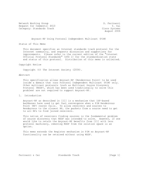
Network Working Group D. Farinacci Request for Comments: 4610 Y. Cai Category: Standards Track Cisco Systems August 2006 Anycast-RP Using Protocol Independent Multicast (PIM)Status of This MemoThis document specifies an Internet standards track protocol for the Internet community, and requests discussion and suggestions forimprovements. Please refer to the current edition of the "InternetOfficial Protocol Standards" (STD 1) for the standardization stateand status of this protocol. Distribution of this memo is unlimited. Copyright NoticeCopyright (C) The Internet Society (2006).AbstractThis specification allows Anycast-RP (Rendezvous Point) to be usedinside a domain that runs Protocol Independent Multicast (PIM) only. Other multicast protocols (such as Multicast Source DiscoveryProtocol (MSDP), which has been used traditionally to solve thisproblem) are not required to support Anycast-RP.1. IntroductionAnycast-RP as described in [I1] is a mechanism that ISP-basedbackbones have used to get fast convergence when a PIM RendezvousPoint (RP) router fails. To allow receivers and sources toRendezvous to the closest RP, the packets from a source need to getto all RPs to find joined receivers.This notion of receivers finding sources is the fundamental problemof source discovery that MSDP was intended to solve. However, if one would like to retain the Anycast-RP benefits from [I1] with lessprotocol machinery, removing MSDP from the solution space is anoption.This memo extends the Register mechanism in PIM so Anycast-RPfunctionality can be retained without using MSDP.Farinacci & Cai Standards Track [Page 1]1.1. TerminologyThe key words "MUST", "MUST NOT", "REQUIRED", "SHALL", "SHALL NOT","SHOULD", "SHOULD NOT", "RECOMMENDED", "MAY", and "OPTIONAL" in this document are to be interpreted as described in [N2].2. Overviewo A unicast IP address is chosen to use as the RP address. Thisaddress is statically configured, or distributed using a dynamicprotocol, to all PIM routers throughout the domain.o A set of routers in the domain is chosen to act as RPs for this RP address. These routers are called the Anycast-RP set.o Each router in the Anycast-RP set is configured with a loopbackinterface using the RP address.o Each router in the Anycast-RP set also needs a separate IP address, to be used for communication between the RPs.o The RP address, or a prefix that covers the RP address, is injected into the unicast routing system inside of the domain.o Each router in the Anycast-RP set is configured with the addresses of all other routers in the Anycast-RP set. This must beconsistently configured in all RPs in the set.3. MechanismThe following diagram illustrates a domain using 3 RPs wherereceivers are joining to the closest RP according to where unicastrouting metrics take them and 2 sources sending packets to theirrespective RPs.The rules described in this section do not override the rules in[N1]. They are intended to blend with the rules in [N1]. If thereis any question on the interpretation, precedent is given to [N1].S1-----RP1 RP2 RP3------S3/ \ |/ \ |R1 R1’ R2Farinacci & Cai Standards Track [Page 2]Assume the above scenario is completely connected where R1, R1’, and R2 are receivers for a group, and S1 and S3 send to that group.Assume RP1, RP2, and RP3 are all assigned the same IP address, which is used as the Anycast-RP address (let’s say the IP address is RPA). Note, the address used for the RP address in the domain (theAnycast-RP address) needs to be different than the addresses used by the Anycast-RP routers to communicate with each other.The following procedure is used when S1 starts sourcing traffic:o S1 sends a multicast packet.o The designated router (DR) directly attached to S1 will form a PIM Register message to send to the Anycast-RP address (RPA). Theunicast routing system will deliver the PIM Register message to the nearest RP, in this case RP1.o RP1 will receive the PIM Register message, decapsulate it, and send the packet down the shared-tree to get the packet to receivers R1and R1’.o RP1 is configured with RP2 and RP3’s IP address. Since theRegister message did not come from one of the RPs in the anycast-RP set, RP1 assumes the packet came from a DR. If the Register is not addressed to the Anycast-RP address, an error has occurred and itshould be rate-limited logged.o RP1 will then send a copy of the Register message from S1’s DR toboth RP2 and RP3. RP1 will use its own IP address as the sourceaddress for the PIM Register message.o RP1 MAY join back to the source-tree by triggering a (S1,G) Joinmessage toward S1. However, RP1 MUST create (S1,G) state.o RP1 sends a Register-Stop back to the DR. If, for some reason, the Register messages to RP2 and RP3 are lost, then when the Registersuppression timer expires in the DR, it will resend Registers toallow another chance for all RPs in the Anycast-RP set to obtainthe (S,G) state.o RP2 receives the Register message from RP1, decapsulates it, andalso sends the packet down the shared-tree to get the packet toreceiver R2.o RP2 sends a Register-Stop back to RP1. RP2 MAY wait to send theRegister-Stop if it decides to join the source-tree. RP2 shouldwait until it has received data from the source on the source-tree Farinacci & Cai Standards Track [Page 3]before sending the Register-Stop. If RP2 decides to wait, theRegister-Stop will be sent when the next Register is received. If RP2 decides not to wait, the Register-Stop is sent now.o RP2 MAY join back to the source-tree by triggering a (S1,G) Joinmessage toward S1. However, RP2 MUST create (S1,G) state.o RP3 receives the Register message from RP1, decapsulates it, butsince there are no receivers joined for the group, it can discardthe packet.o RP3 sends a Register-Stop back to RP1.o RP3 creates (S1,G) state so when a receiver joins after S1 startssending, RP3 can join quickly to the source-tree for S1.o RP1 processes the Register-Stop from each of RP2 and RP3. There is no specific action taken when processing Register-Stop messages.The procedure for S3 sending follows the same as above but it is RP3 that sends a copy of the Register originated by S3’s DR to RP1 andRP2. Therefore, this example shows how sources anywhere in thedomain, associated with different RPs, can reach all receivers, also associated with different RPs, in the same domain.4. Observations and Guidelines about This Proposalo An RP will send a copy of a Register only if the Register isreceived from an IP address not in the Anycast-RP list (i.e., theRegister came from a DR and not another RP). An implementationMUST safeguard against inconsistently configured Anycast-RP sets in each RP by copying the Time to Live (TTL) from a Register messageto the Register messages it copies and sends to other RPs.o Each DR that PIM registers for a source will send the message tothe Anycast-RP address (which results in the packet getting to the closest physical RP). Therefore, there are no changes to the DRlogic.o Packets flow to all receivers no matter what RP they have joinedto.o The source gets Registered to a single RP by the DR. It’s theresponsibility of the RP that receives the PIM Register messagesfrom the DR (the closest RP to the DR based on routing metrics) to get the packet to all other RPs in the Anycast-RP set.Farinacci & Cai Standards Track [Page 4]o Logic is changed only in the RPs. The logic change is for sending copies of Register messages. Register-Stop processing isunchanged. However, an implementation MAY suppress sendingRegister-Stop messages in response to a Register received from anRP.o The rate-limiting of Register and Register-Stop messages are doneend-to-end. That is from DR -> RP1 -> {RP2 and RP3}. There is no need for specific rate-limiting logic between the RPs.o When topology changes occur, the existing source-tree adjusts as it does today according to [N1]. The existing shared-trees, as well, adjust as they do today according to [N1].o Physical RP changes are as fast as unicast route convergence,retaining the benefit of [I1].o An RP that doesn’t support this specification can be mixed with RPs that do support this specification. However, the non-supporter RP should not have sources registering to it, but may have receiversjoined to it.o If Null Registers are sent (Registers with an IP header and no IPpayload), they MUST be replicated to all of the RPs in theAnycast-RP set so that source state remains alive for activesources.o The number of RPs in the Anycast-RP set should remain small so the amount of non-native replication is kept to a minimum.o Since the RP, who receives a Register from the DR, will send copies of the Register to the other RPs at the same time it sends aRegister-Stop to the DR, there could be packet loss and lost state in the other RPs until the time the DR sends Register messagesagain.5. Interaction with MSDP Running in an Anycast-PIM RouterThe objective of this Anycast-PIM proposal is to remove thedependence on using MSDP. This can be achieved by removing MSDPpeering between the Anycast-RPs. However, to advertise internalsources to routers outside of a PIM routing domain and to learnexternal sources from other routing domains, MSDP may still berequired.Farinacci & Cai Standards Track [Page 5]5.1. Anycast-PIM Stub Domain FunctionalityIn this capacity, when there are internal sources that need to beadvertised externally, an Anycast-RP that receives a Registermessage, either from a DR or an Anycast-RP, should process it asdescribed in this specification as well as how to process a Register message as described in [N1]. That means a Source-Active (SA) forthe same internal source could be originated by multiple Anycast-RPs doing the MSDP peering. There is nothing inherently wrong with this other than that the source is being advertised into the MSDPinfrastructure from multiple places from the source domain. However, if this is not desirable, configuration of one or more (rather thanall) Anycast-RP MSDP routers would allow only those routers tooriginate SAs for the internal source. And in some situations, there is a good possibility not all Anycast-RPs in the set will have MSDPpeering sessions so this issue can be mitigated to a certain extent. From an Anycast-RP perspective, a source should be consideredinternal to a domain when it is discovered by an Anycast-RP through a received Register message, regardless of whether the Register message was sent by a DR, another Anycast-RP member, or the router itself.For learning sources external to a domain, the MSDP SA messages could arrive at multiple MSDP-peering Anycast-RPs. The rules forprocessing an SA, according to [I1], should be followed. That is, if G is joined in the domain, an (S,G) join is sent towards the source. And if data accompanies the SA, each Anycast-PIM RP doing MSDPpeering will forward the data down each of its respective shared-trees.The above assumes each Anycast-RP has external MSDP peeringconnections. If this is not the case, the Anycast-PIM routers withthe MSDP peering connections would follow the same procedure as if a Data-Register or Null-Register was received from either a DR oranother Anycast-RP. That is, they would send Registers to the other members of the Anycast-RP set.If there is a mix of Anycast-RPs that do and do not have externalMSDP peering connections, then the ones that do must be configuredwith the set that do not. So Register messages are sent only to the members of the Anycast-RP set that do not have external MSDP peering connections.The amount of Register traffic generated by this MSDP-peering RPwould be equal to the number of active sources external to thedomain. The Source-Active state would have to be conveyed to allother RPs in the Anycast-RP set since the MSDP-peering RP would notknow about the group membership associated with the other RPs. To Farinacci & Cai Standards Track [Page 6]avoid this periodic control traffic, it is recommended that allAnycast-RPs be configured with external MSDP peering sessions so noRP in the Anycast-RP set will have to originate Register messages on behalf of external sources.5.2. Anycast-PIM Transit Domain FunctionalityWithin a routing domain, it is recommended that an Anycast-RP setdefined in this specification should not be mixed with MSDP peeringamong the members. In some cases, the source discovery will work but it may not be obvious to the implementations which sources are local to the domain and which are not. This may affect external MSDPadvertisement of internal sources.Having said that, this document makes no attempt to connect MSDPpeering domains together by using Anycast-PIM inside a transitdomain.6. Security ConsiderationThis section describes the security consideration for Register andRegister-Stop messages between Anycast-RPs. For PIM messages between DR and RP, please see [N1].6.1. Attack Based On Forged MessagesAn attacker may forge a Register message using one of the addressesin the Anycast-RP list in order to achieve one or more of thefollowing effects:1. Overwhelm the target RP in a denial-of-service (DoS) attack2. Inject unauthorized data to receivers served by the RP3. Inject unauthorized data and create bogus SA entries in otherPIM domains if the target RP has external MSDP peeringsAn attacker may also forge a Register-Stop message using one of theaddresses in the Anycast-RP list. However, besides denial-of-service, the effect of such an attack is limited because an RPusually ignores Register-Stop messages.6.2. Protect Register and Register-Stop MessagesThe DoS attack using forged Register or Register-Stop messages cannot be prevented. But the RP can still be protected. For example, theRP can rate-limit incoming messages. It can also choose to refuse to process any Register-Stop messages. The actual protection mechanism is implementation specific.Farinacci & Cai Standards Track [Page 7]The distribution of unauthorized data and bogus Register messages can be prevented using the method described in section 6.3.2 of [N1].When RP1 sends a copy of a register to RP2, RP1 acts as [N1]describes the DR and RP2 acts as [N1] describes the RP.As described in [N1], an RP can be configured using a unique SA andSecurity Parameter Index (SPI) for traffic (Registers or Register-Stops) to each member of Anycast-RPs in the list, but this results in a key management problem; therefore, it may be preferable in PIMdomains where all Rendezvous Points are under a single administrative control to use the same authentication algorithm parameters(including the key) for all Registered packets in a domain.7. AcknowledgementsThe authors prototyped this document in the cisco IOS and Procketimplementations, respectively.The authors would like to thank John Zwiebel for doinginteroperability testing of the two prototype implementations.The authors would like to thank Thomas Morin from France Telecom for having an extensive discussion on Multicast the Registers to an SSM- based full mesh among the Anycast-RP set. This idea may come in asubsequent document.And finally, the authors would like to thank the following for their comments on earlier drafts:Greg Shepherd (Procket Networks (now Cisco Systems))Lenny Giuliano (Juniper Networks)Prashant Jhingran (Huawei Technologies)Pekka Savola (CSC/FUNET)Bill Fenner (AT&T)James Lingard (Data Connection)Amit Shukla (Juniper Networks)Tom Pusateri (Juniper Networks)Farinacci & Cai Standards Track [Page 8]8. References8.1. Normative References[N1] Fenner, B., Handley, M., Holbrook, H., and I. Kouvelas,"Protocol Independent Multicast - Sparse Mode (PIM-SM):Protocol Specification (Revised)", RFC 4601, August 2006.[N2] Bradner, S., "Key words for use in RFCs to Indicate Requirement Levels", BCP 14, RFC 2119, March 1997.8.2. Informative References[I1] Kim, D., Meyer, D., Kilmer, H., and D. Farinacci, "AnycastRendevous Point (RP) mechanism using Protocol IndependentMulticast (PIM) and Multicast Source Discovery Protocol (MSDP)", RFC 3446, January 2003.Farinacci & Cai Standards Track [Page 9]Appendix A: Possible Configuration LanguageA possible set of commands to be used could be:ip pim anycast-rp <anycast-rp-addr> <rp-addr>Where:<anycast-rp-addr> describes the Anycast-RP set for the RP that is assigned to the group range. This IP address is the address that first-hop and last-hop PIM routers use to register and join to.<rp-addr> describes the IP address where Register messages copies are sent to. This IP address is any address assigned to the RProuter not including the <anycast-rp-addr>.Example:From the illustration above, the configuration commands would be: ip pim anycast-rp RPA RP1ip pim anycast-rp RPA RP2ip pim anycast-rp RPA RP3Comment:It may be useful to include the local router IP address in thecommand set so the above lines can be cut-and-pasted or scriptedinto all the RPs in the Anycast-RP set.But the implementation would have to be aware of its own addressand not inadvertently send a Register to itself.Farinacci & Cai Standards Track [Page 10]Authors’ AddressesDino FarinacciCisco SystemsEMail: dino@Yiqun CaiCisco SystemsEMail: ycai@Farinacci & Cai Standards Track [Page 11]Full Copyright StatementCopyright (C) The Internet Society (2006).This document is subject to the rights, licenses and restrictionscontained in BCP 78, and except as set forth therein, the authorsretain all their rights.This document and the information contained herein are provided on an "AS IS" basis and THE CONTRIBUTOR, THE ORGANIZATION HE/SHE REPRESENTS OR IS SPONSORED BY (IF ANY), THE INTERNET SOCIETY AND THE INTERNETENGINEERING TASK FORCE DISCLAIM ALL WARRANTIES, EXPRESS OR IMPLIED,INCLUDING BUT NOT LIMITED TO ANY WARRANTY THAT THE USE OF THEINFORMATION HEREIN WILL NOT INFRINGE ANY RIGHTS OR ANY IMPLIEDWARRANTIES OF MERCHANTABILITY OR FITNESS FOR A PARTICULAR PURPOSE. Intellectual PropertyThe IETF takes no position regarding the validity or scope of anyIntellectual Property Rights or other rights that might be claimed to pertain to the implementation or use of the technology described inthis document or the extent to which any license under such rightsmight or might not be available; nor does it represent that it hasmade any independent effort to identify any such rights. Information on the procedures with respect to rights in RFC documents can befound in BCP 78 and BCP 79.Copies of IPR disclosures made to the IETF Secretariat and anyassurances of licenses to be made available, or the result of anattempt made to obtain a general license or permission for the use of such proprietary rights by implementers or users of thisspecification can be obtained from the IETF on-line IPR repository at /ipr.The IETF invites any interested party to bring to its attention anycopyrights, patents or patent applications, or other proprietaryrights that may cover technology that may be required to implementthis standard. Please address the information to the IETF atietf-ipr@.AcknowledgementFunding for the RFC Editor function is provided by the IETFAdministrative Support Activity (IASA).Farinacci & Cai Standards Track [Page 12]。
ONVIF2.0中文协议原版

ONVIF2.0中文协议原版1 范围 (17)2 引用标准 (20)3 术语与定义 (27)3.1定义 (27)3.2缩写 (31)4 概述 (38)4.1W EB 服务 (39)4.2IP配置 (41)4.3设备发现 (41)4.4设备类型 (42)4.5设备管理 (43)4.5.1 功能 (43)4.5.2 网络 (45)4.5.3 系统 (45)4.5.4 系统信息检索 (46)4.5.5 固件升级 (46)4.5.6 系统还原 (47)4.5.7 安全 (47)4.6设备IO (47)4.7图像配置 (49)4.8媒体配置 (50)4.8.1 媒体配置文件 (50)4.9实时流 (56)4.10事件处理 (58)4.11PTZ控制 (58)4.12视频分析 (60)4.13分析设备 (63)4.14显示 (64)4.15接收器 (65)4.15.1 同步点 (66)4.16存储 (66)4.16.1 存储模式 (67)4.16.2 记录 (69)4.16.3 查找 (70)4.16.4 回放 (72)4.17安全 (72)5 WEB服务框架 (74)5.1服务概述 (75)5.1.1 服务要求 (76)5.2WSDL概述 (77)5.3命名空间 (78)5.4类型 (91)5.5消息 (92)5.6操作 (93)5.6.1 单向操作 (95)5.6.2 要求-应答操作类型 (96)5.7端口类型 (98)5.8绑定 (98)5.9端口 (99)5.10服务 (99)5.11错误处理 (99)5.11.1 协议错误 (100)5.11.2 SOAP错误 (100)5.11.2.1常见的故障 (104)5.11.2.2 具体的错误 (106)5.11.2.3 HTTP错误 (106)5.12安全 (107)5.12.1 基于用户访问控制 (109)5.12.2 用户令牌配置文件 (109)5.12.2.1密码推导 (110)5.12.2.1.1 例子 (111)6 IP配置 (113)7 设备发现 (114)7.1概述 (115)7.2操作模式 (115)7.3发现定义 (116)7.3.1 终端参考 (116)7.3.2 服务地址 (117)7.3.3 Hello (117)7.3.3.1类型 (117)7.3.3.2范围 (117)7.3.3.2.1例子 (122)7.3.3.3 地址 (123)7.3.4 探头和探头匹配 (123)7.3.5 解决和解决匹配 (124)7.3.6 BYE (124)7.3.7 SOAP错误信息 (124)7.4远程发现扩展 (126)7.4.1 网络情景 (126)7.4.2 发现代理 (129)7.4.2.1 直接的DP地址配置 (131)7.4.2.2 域名服务记录的查找 (131)7.4.3 远程hello和探头行为 (132)7.4.4 客户端行为 (133)7.4.4.1 NVC 本地DP配置 (134)7.4.5 安全 (135)7.4.5.1 本地发现 (135)7.4.5.2 远程发现 (135)8设备管理 (136)8.1功能 (137)8.1.1获取WSDL的URL (137)8.1.2交换的功能 (138)8.2网络 (150)8.2.1获取主机 (150)8.2.2设置主机名 (151)8.2.3 获取 DNS配置 (152)8.2.4设置DNS (154)8.2.5获取NTP配置信息 (155)8.2.6 对设备设置NTP (157)8.2.7获取动态的DNS设置 (158)8.2.8设置设备动态DNS (160)8.2.9 获取网络接口配置 (161)8.2.10 设置网络接口配置 (162)8.2.11 获取网络协议 (166)8.2.12 设置网络协议 (167)8.2.13 获取默认的网关 (168)8.2.14 设置默认网关 (169)8.2.15 获取0配置 (170)8.2.16 设置0配置 (172)8.2.17 获取IP地址过滤 (173)8.2.18 对IP地址过滤进行配置 (175)8.2.19 增加IP地址过滤 (176)8.2.20 移除IP地址过滤 (178)8.2.21 IEEE 802.11配置 (180)8.2.21.1 SSID (181)8.2.21.2 基站模式 (181)8.2.21.3 多种无线网络配置 (182)8.2.21.4 安全配置 (183)8.2.21.4.1 None 模式 (184)8.2.21.4.2 PSK模式 (184)8.2.21.4.3 IEEE 802.1X-2004 模式 (185)8.2.21.5 获取DOT11的性能 (185)8.2.21.6 GetIEEE802.11状态 (186)8.2.21.7 扫描可用的IEEE802.11网络 (188)8.3系统 (190)8.3.1设备信息 (190)8.3.2获取系统的URL (191)8.3.3备份 (193)8.3.4恢复 (194)8.3.5开始恢复系统 (195)8.3.6获取系统日期以及时间 (197)8.3.7设置系统日期以及时间 (200)8.3.8 出厂默认配置 (202)8.3.9 固件升级 (204)8.3.10 开始固件升级 (206)8.3.11 获取系统日志 (208)8.3.12 获取支持信息 (210)8.3.13 重启 (212)8.3.14 获取范围参数 (212)8.3.15设置范围参数 (214)8.3.16 添加范围参数 (215)8.3.17 移除范围参数 (216)8.3.18 获取发现模式 (217)8.3.19 设置发现模式 (218)8.3.20 获取远程发现方式 (219)8.3.21 设置远程发现方式 (220)8.3.22 获取远程DP地址 (221)8.3.23 配置远程DP地址 (222)8.4安全 (223)8.4.1获取访问策略 (223)8.4.2 设置访问策略 (224)8.4.3 获取用户 (225)8.4.4 创建用户 (226)8.4.5 删除用户 (228)8.4.6 对用户进行配置 (230)8.4.7 IEEE 802.1X配置 (231)8.4.7.1创建IEEE802.1X配置 (233)8.4.7.2对IEEE802.1X配置 (235)8.4.7.3 获取IEEE802.1X配置 (236)8.4.7.4获取IEEE802.1X配置 (237)8.4.7.5 删除IEEE802.1X配置 (239)8.4.8 创建签名证书 (240)8.4.9 获取证书 (242)8.4.10 获取CA证书 (243)8.4.11获取证书状态 (244)8.4.12 设置证书状态 (245)8.4.13获取证书请求 (246)8.4.14 获取客户证书状态 (248)8.4.15 设置客户认证状态 (249)8.4.16 下载设备证书 (250)8.4.17 利用私有密钥来链接下载设备证书 (252)8.4.18 获取证书信息请求 (254)8.4.19 下载CA证书 (256)8.4.20 删除证书 (257)8.4.21 获取远程用户 (259)8.4.22 设置远程用户 (260)8.4.23获取终端参数 (261)8.5输入与输出 (262)8.5.1获取继电器输出 (263)8.5.2 对继电器输出进行配置 (263)8.5.3继电器触发输出 (265)8.5.4 辅助操作 (267)8.6与服务相关的错误代码 (268)9设备IO服务 (283)9.1视频输出 (284)9.1.1 获取视频输出集 (284)9.2视频输出配置 (285)9.2.1 获取视频输出配置 (285)9.2.2 设置视频输出配置 (286)9.2.3 获取视频输出配置选项集 (287)9.3视频源 (289)9.3.1 获取视频源 (289)9.4视频源配置 (291)9.4.1 获取视频源配置 (291)9.4.2 设置视频源配置 (292)9.4.3 获取视频源多个配置选项 (294)9.5音频输出 (296)9.5.1 获取多个音频输出 (296)9.6音频输出配置 (297)9.6.1 获取音频输出配置 (297)9.6.2 设置音频输出配置 (299)9.6.3 获取音频输出多个配置选项 (301)9.7音频源 (302)9.7.1 获取音频源 (302)9.8音频源配置 (304)9.8.1 获取音频源配置 (304)9.8.2 设置音频源配置 (305)9.8.3 获取音频源多个配置选项 (307)9.9继电器输出 (309)9.9.1 获取多个继电器输出 (309)9.9.2 设置继电器输出设置 (310)9.9.3 触发继电器输出 (312)9.10服务错误码 (314)10图像配置 (317)10.1图像设置 (317)10.1.1 获取图像设置 (321)10.1.2 设置图像设置 (323)10.1.3 获取选项 (326)10.1.4 移动 (327)10.1.5 获取运行选项 (330)10.1.6 停止 (332)10.1.7 获取图像状态 (333)10.2服务错误码 (335)11媒体配置 (337)11.1音视频编解码器 (338)11.2媒体文件 (339)11.2.1 创建媒体文件 (340)11.2.2 获取多个媒体文件 (342)11.2.3 获取媒体文件 (343)11.2.4 添加视频源配置 (345)11.2.5 添加视频编码器配置 (346)11.2.6 添加音频源配置 (348)11.2.7 添加音频源编码器配置 (349)11.2.8 添加云台配置 (351)11.2.9 添加视频分析配置 (353)11.2.10 添加元数据配置 (356)11.2.11 添加音频输出配置 (358)11.2.12 添加音频解码器配置 (359)11.2.13 移除视频源配置 (361)11.2.14 移除视频源编码器配置 (362)11.2.15 移除音频源编码器配置 (364)11.2.16 移除音频编码器配置 (365)11.2.17 移除云台配置 (367)11.2.18 移除视频分析配置 (368)11.2.19 移除元数据配置 (370)11.2.20 移除音频输出配置 (371)11.2.21 移除音频编码器配置 (372)11.2.22 删除媒体文件 (374)11.3视频源 (375)11.3.1 获取视频源集 (375)11.4视频源配置 (376)11.4.1 获取视频源配置集 (376)11.4.2 获取视频源配置 (378)11.4.3 获取多个兼容视频源配置 (379)11.4.4 获取视频源配置选项 (380)11.4.5 设置视频源配置 (382)11.5视频编码器配置 (384)11.5.3 获取多个兼容视频解码器配置 (387)11.5.4 获取视频编码器配置选项集 (389)11.5.5 修改视频编码器配置 (392)11.5.6 获取有效的视频编码数量 (394)11.6音频源 (396)11.6.1 获取多个音频源 (396)11.7音频源配置 (397)11.7.1 获取多个音频源配置 (397)11.7.2 获取音频源配置 (398)11.7.3 获取兼容音频源配置集 (400)11.7.4 获取音频源配置选项集 (402)11.7.5 修改音频源配置 (404)11.8音频编码器配置 (407)11.8.1 获取多个音频编码器配置 (408)11.8.2 获取音频源编码器配置 (409)11.8.3 获取多个兼容音频编码器配置 (410)11.8.4 获取音频编码器配置选项集 (412)11.8.5 设置音频编码配置 (414)11.9视频分析配置 (417)11.9.1 获取多个视频分析配置 (418)11.9.2 获取视频分析配置 (419)11.9.3 获取多个兼容视频分析配置 (421)11.9.4 修改视频分析配置 (423)11.10元数据配置 (425)11.10.1 获取多个元数据配置 (426)11.10.2 获取元数据配置 (427)11.10.3 获取多个兼容元数据配置 (428)11.10.4 获取元数据配置选项集 (429)11.10.5 修改元数据配置 (431)11.11音频输出 (434)11.11.1 获取音频输出集 (434)11.12音频输出配置 (435)11.12.1 获取多个音频输出配置 (435)11.12.2 获取音频输出配置 (437)11.12.3 获取多个兼容音频输出配置 (438)11.12.4 获取音频输出配置选项集 (440)11.12.5 设置音频输出配置 (442)11.13音频解码器配置 (444)11.13.1 获取多个音频解码器配置 (444)11.13.2 获取音频解码器配置 (445)11.13.3 获取兼容音频解码器配置集 (447)11.13.4 获取音频解码器配置选项集 (449)11.15URI流 (454)11.15.1 获取Uri流 (454)11.16快照 (457)11.16.1 获取Uri快照 (457)11.17组播 (459)11.17.1 开始组播流 (459)11.17.2 停止组播流 (461)11.18同步点 (462)11.18.1 设置同步点 (462)11.19服务具体的错误码 (464)12 实时流 (470)12.1流媒体协议 (470)12.1.1传输格式 (470)12.1.1.1通过UDP的RTP数据传输 (471)12.1.1.2 通过TCP传输RTP数据 (471)12.1.1.3 RTP/RTSP/TCP (471)12.1.1.4 RTP/RTSP/HTTP/TCP (471)12.1.2 媒体传输 (472)12.1.2.1 RTP (472)12.1.2.1.1 RTP元数据流 (476)12.1.2.2 RTCP (478)12.1.2.2.1媒体同步 (479)12.1.3 同步点 (481)12.1.4 通过RTP传输JPEG (482)12.1.4.1所有包的结构 (482)12.1.4.2 逻辑解码规范 (484)12.1.4.3支持的彩色空间和采样因素 (487)12.1.4.4像素长宽比处理 (487)12.1.4.5 隔行扫描处理 (488)12.2媒体控制协议 (488)12.2.1流控制 (488)12.2.1.1 RTSP (489)12.2.1.1.1 保持RTSP会话的方法 (491)12.2.1.1.2 RTSP音频和视频同步 (492)12.2.1.1.4 RTSP消息的例子 (493)12.2.1.2 通过HTTP的RSTP (494)12.3往回通道连接 (495)12.3.1 RTSP协议请求的标签 (495)12.3.2双向连接的连接设置 (496)12.3.2.1 例一:没有往回支持的服务 (496)12.3.2.2 例二:使用ONVIF往回通道支持的服务 (497)12.3.3组播流 (499)12.3.3.1例:多播设置 (499)12.4错误处理 (499)13 接收端配置 (500)13.1持久性 (501)13.2接收端模式 (501)13.3接收命令 (501)13.3.1 获得多个接收器 (501)13.3.2 获得单个接收器 (502)13.3.3 创建接收器 (503)13.3.4 删除接收器 (504)13.3.5 配置接收器 (504)13.3.6 设计接收器模式 (506)13.3.7 获取接收机状态 (506)13.4事件 (507)13.4.1 改变状态 (507)13.4.2 连接失败 (508)13.5服务器错误码 (509)14 显示服务 (512)14.1窗格 (513)14.1.1 获得多个窗格配置 (515)14.1.2 获得单个窗格配置 (516)14.1.3 设置多个窗格配置 (517)14.1.4 设置单个窗格配置 (518)14.1.5 创建窗格配置 (520)14.1.6 删除窗格配置 (521)14.2布局 (522)14.2.1 获得布局 (523)14.2.2 设置布局 (524)14.3显示选项 (524)14.3.1 获取显示选项 (526)14.4事件 (526)14.4.1 解码错误事件 (527)14.5服务错误码 (528)15 事件处理 (532)15.1基本通知接口 (533)15.1.1 介绍 (534)15.1.2 要求 (536)15.2实时拉点通知接口 (537)15.2.1 创建 pull point subscription (540)15.2.2 pull 消息 (541)15.3通知流接口 (542)15.5通知结构 (544)15.5.1 通知消息 (547)15.5.1.1 事件例子 (548)15.5.2 消息格式 (549)15.5.3 属性举例,持续 (553)15.5.4 信息描述语言 (558)15.5.4.1 消息描述举例 (560)15.5.5 消息内容过滤器 (562)15.6同步点 (565)15.7主题结构 (567)15.7.1 ONVIF主题名字空间 (567)15.7.2 主题类型信息 (569)15.7.3 主题过滤器 (572)15.8获取事件属性 (575)15.9SOAP错误消息 (578)15.10通知例子 (578)15.10.1 获取事件属性请求 (578)15.10.2 获取事件属性应答 (579)15.10.3 创建PULLPOIT订阅 (583)15.10.4 创建PULLPOIT订阅应答 (586)15.10.5 拉消息请求 (588)15.10.6 拉消息应答 (590)15.10.7 退订请求 (594)15.10.8 退订应答 (596)15.11服务错误码 (597)16 PTZ控制 (597)16.1PTZ模型 (599)16.2PTZ节点 (602)16.2.1 获取所有节点(GetNodes) (603)16.2.2 获取节点(GetNode) (604)16.3PTZ配置 (605)16.3.1 读取所有配置命令(GetConfigurations) (608)16.3.2 读取配置命令(GetConfiguration) (609)16.3.3 读取配置选项(GetConfigurationOptions) (610)16.3.4 设置配置(SetConfiguration) (612)16.4移动操作 (614)16.4.1 绝对的移动(AbsoluteMove) (614)16.4.2 相对移动(RelativeMove) (617)16.4.3 连续移动(ContinuousMove) (620)16.4.4 停止(Stop) (623)16.4.5 读取状态(GetStatus) (624)16.5.2 读取所有预设值(GetPresets) (629)16.5.3 返回预设 (630)16.5.4 移除预设(RemovePreset) (632)16.6归位点操作 (634)16.6.1 转到归位点(GotoHomePosition) (634)16.6.2 设置归位点(SetHomePosition) (636)16.7辅助操作 (637)16.7.1 发送辅助命令(SendAuxiliaryCommand) (638)16.8预定PTZ空间 (640)16.8.1 绝对的位置空间 (640)16.8.1.1 泛化的全方位移动空间 (640)16.8.1.2 泛化的变焦位置空间 (641)16.8.2 相对的转换空间 (642)16.8.2.1 泛化的方位转换空间 (642)16.8.2.2 泛化的变焦转换空间 (643)16.8.3 连续的速率空间 (644)16.8.3.1 泛化的方位速率空间 (644)16.8.3.2 泛化的变焦速率空间 (646)16.8.4 速度空间 (646)16.8.4.1 泛化的方位速度空间 (647)16.8.4.2 泛化的变焦速度空间 (647)16.9服务错误码 (648)17 视频分析 (658)17.1场景描述接口 (659)17.1.1 概述 (659)17.1.2 画面相关内容 (660)17.1.2.1时间关系 (662)17.1.2.2 空间关系 (663)17.1.3 场景元素 (666)17.1.3.1 对象 (667)17.1.3.2 对象树 (674)17.1.3.3 形状描述符 (678)17.2规则接口 (680)17.2.1 规则陈述 (681)17.2.2 规则描述语言 (683)17.2.3 规则标准 (687)17.2.3.1 线性检测器 (687)17.2.3.2 域检测器 (689)17.2.4 规则操作 (691)17.2.4.1 读取支持的操作(GetSupportedRules) (692)17.2.4.2 读取规则(GetRules) (693)17.2.4.3 创建规则(CreateRules) (694)17.2.4.4 修改规则(ModifyRules) (696)17.4.4.5 删除规则(DeleteRules) (697)17.3分析模块接口 (699)17.3.1 分析模块配置 (699)17.3.2 分析模块描述语言 (701)17.3.3 分析模块操作 (703)17.3.3.1 读取支持的分析模块(GetSupportedAnalysticsModule) (703)17.3.3.2 读取模块分析(GetAnalyticsModules) (705)17.3.3.3 创建分析模块(CreateAnalyticsModules) (706)17.3.3.4 修改分析模块(ModifyAnalyticsModules) (708)17.3.3.5 删除分析模块(DeleteAnalyticsModules) (710)17.4服务错误码 (711)18分析设备 (719)18.1概述 (720)18.2分析引擎输入 (721)18.2.1获取分析引擎输入 (722)18.2.2获取分析引擎的输入 (723)18.2.3设置分析引擎的输入 (724)18.2.4 创建分析引擎输入 (726)18.2.5删除分析引擎输入 (728)18.3视频分析配置 (729)18.3.1 获取视频分析配置 (729)18.3.2 设置视频分析配置 (730)18.4分析引擎 (732)18.4.1获取分析引擎 (732)18.4.2 获取分析引擎 (733)18.5分析引擎控制 (734)18.5.1 GetAnalyticsEngineControls (735)18.5.2 获取分析引擎控制 (737)18.5.3设置分析引擎控制 (738)18.5.4 CreateAnalyticsEngineControl (739)18.5.5删除分析引擎控制 (741)18.6获取分析状态 (742)18.7输出流配置 (744)18.7.1 请求流的URL (745)19录制控制 (747)19.1介绍 (747)19.2一般要求 (750)19.3数据结构 (750)19.3.1 录制设置 (751)19.3.2 轨迹设置 (751)19.3.3 录制任务设置 (752)19.4创建录制 (754)19.5删除录制 (757)19.6获取录制集 (758)19.7设置录制配置 (759)19.8获取录制配置 (760)19.9创建轨道 (761)19.10删除轨道 (763)19.11获取轨道配置 (765)19.12设置轨道配置 (766)19.13创建录制任务 (768)19.14删除录制任务 (770)19.15获取录制任务集 (771)19.16设置录制任务配置 (772)19.17获取录制任务配置 (774)19.18设置录制模式 (775)19.19获取录制任务状态 (777)19.20事件 (780)19.20.1 录制任务状态变化 (780)19.20.2 设置变化 (781)19.20.3 删除数据 (784)19.20.4 录制和轨道的建立与删除 (785)19.21示例 (787)19.21.1 例1:单摄像头的安装录制 (787)19.21.2 例2:从一台摄像机录制多个流到一个单录制 (789)20 记录搜索 (791)20.1介绍 (791)20.2概念 (792)20.2.1 搜索方向 (792)20.2.2 记录事件 (792)20.2.3 查找对话 (793)20.2.4 查找范围 (794)20.2.4.1 包括的数据 (794)20.2.4.2 记录信息滤波器 (795)20.2.5 搜索过滤器 (795)20.3数据结构 (795)20.3.1 记录信息结构 (795)20.3.2 记录源信息结构 (796)20.3.3 跟踪信息结构 (796)20.3.4 列举查找状态 (797)20.3.5 媒体属性结构 (797)20.3.6 找事件结果结构 (798)20.3.7 找PTZ位置结果结构 (798)20.3.8 PTZ位置过滤结构 (799)20.3.9 元数据过滤结果 (799)20.3.10 找元数据结果结构 (799)20.4获取记录概要(G ET R ECORDING S UMMARY) (800)20.5读取记录信息(G ET R ECORDING I NFORMATION) (801)20.6读取媒体属性(G ET M EDIA A TTRIBUTES) (802)20.7找记录(F IND R ECORDINGS) (804)20.8获取记录搜索结果(G ET R ECORDING S EARCH R ESULTS) (806)20.9找事件(F IND E VENTS) (808)20.10读取事件搜索结果(G ET E VENT S EARCH R ESULTS) (811)20.11查找PTZ位置(F IND PTZP OSITION) (814)20.12读取PTZ位置搜索结果(G ET PTZP OSITION S EARCH R ESULTS) (818)20.13查找元数据(F IND M ETADATA) (821)20.14读取元数据搜索结果(G ET M ETADATA S EARCH R ESULTS) (824)20.15获取搜索状态(G ET S EARCH S TATE) (827)20.16结束搜索(E ND S EARCH) (828)20.17记录事件说明 (829)20.18XP ATH习惯用法 (834)21 重放控制 (837)21.1使用RTSP协议 (837)21.1.1 RTSP描述 (838)21.2RTP协议头部扩展 (839)21.2.1 NTP时间戳 (841)21.2.2 压缩JEPG头扩展的兼容 (841)21.3RTSP特性标签 (842)21.4启动播放 (843)21.4.1 领域范围 (844)21.4.2 速度控制头领域 (846)21.4.3 帧头字段 (846)21.4.4 同步点 (848)21.5回放 (848)21.5.1 数据包传输顺序 (848)21.5.2 RTP传输顺序号 (849)21.5.3 RTP时间戳 (849)21.6RTSP长连接 (850)21.7当前记录片段 (851)21.8结束片段 (851)21.9拖放 (852)21.10使用RTCP协议 (853)21.11重放命令 (853)21.11.1 重放命令 (853)21.11.2 重播配置 (855)21.11.3 设置重播配置 (856)21.11.4 获取重播配置 (857)21.11.5 服务指定的误码 (857)22 安全 (861)22.1传输层安全 (862)22.1.1 支持密码套 (863)22.1.2 服务器身份验证 (863)22.1.3 客户端认证 (864)22.2消息安全 (864)22.3IEEE802.1X (865)介绍ONVIF的目标是为了实现完全标准化的、可互操作性的网络视频服务,即使是由不同的网络视频供应商组成的产品。
千兆光猫用户手册说明书
The CODA-5519is a powerful router that will be used as the heart of your wireless home.It will offer strong Wi-Fi that will covers most houses.The CODA-5519has the capability to receive 5Gbps bi-directional based on 2OFDM +32QAM downstream channels and with 2OFDMA +8upstream channels over its DOCSIS 3.1interface.The integrated Wi-Fi 4x42.4GHz 802.11ax and 4x45GHz 802.11ax dual band MU-MIMO Access Point significantly improves customer experience extending range and coverage with blazing speeds.For wired clients,2.5G plus two Gigabit Ethernet ports offer ultra-fast connection.It can be paired with Hitron extenders/mesh pods for extra coverage.•DOCSIS 3.1 2x2 multi-carrier OFDM •DOCSIS 3.0 32x8 channel bonding•4x4 2.4GHz 802.11ax and 4x4 5GHz 802.11ax dual band concurrent MU-MIMO internal antennas •16 SSIDs (8SSIDs per radio)•Individual configuration for each SSID (security, bridging, routing, firewall and Wi-Fi parameters)•Extensive operator control via configuration file and SNMP•Integrated DLNA Media Server with support for video, audio and image servingDOCSIS 3.1 Wi-Fi 6 and eMTA GatewayIntel® Puma™ 7 OFDM 2x2 w / fixed upstream, 4x4 dual band Wi-Fi w/ concurrent 802.11ax 2.4Ghz + 5GHz, MoCA 2.0 channel bonding and voice HIGH PERFORMANCE INTERNET AND WIRELESS ACCESSThe CODA-5519supports pre-configured and pre-enabled Wi-Fi security via Wi-Fi Protected Setup (WPS),allowing the end-user to rapidly set up a secure wireless network without manual configuration.Hitron's AutoSync software provides secure automated setup of extenders in the customer's home or business.It comes with MyHitron (end user management mobile application).MSO can also get extra management and analytics via HitronCloud/OptiMy CSR interface from the support center.SECURE WIRELESS NETWORKING CONTROLLED AT THE TIP OF YOUR FINGERSKEY FEATURES•IPv6 routing•MoCA 2.0 channel bonding•TR-069 and HNAP for easy setup and remote management•Enhanced management and stability for low total cost of ownership•One 2.5G and Two 1G Ethernet ports •Hitron Ecosystem Support (OptiMy, HitronCloud, MyHitron)•2 HD voice ports with SIP or MGCP supportTVStreamer Smartphone TabletThermostatHome Security LaptopCODA-5519Printer PCMoCA ExtenderPhonesWi-Fi1G Ethernet Analog2.5G Ethernet Coax PodLaptop Gaming ConsoleConnectivity•RF F-Type 75Ωfemale connector•2x RJ-45 Ethernet port 10/100/1000Mbps•1x RJ-45 Ethernet port 10/100/1000/2500Mbps•USB 3.0 type A connector with host interface•2x RJ-11 HD voice ports•EBBU jackManagement•Protocol support: TR-069, TFTP, SSHv2, SNMP v2C, v3•Web-based GUI control, configuration and management •Power-on self diagnostic•Hitron proprietary MIBs for extended support onDOCSIS, router management, Wi-Fi managementand MoCA management•app support•and back end supportReception-Demodulation•DOCSIS 3.1/3.0/2.0•DOCSIS 3.1 demodulation: Multi-carrier OFDM 16 to 4096QAM •DOCSIS 3.1 data rate: Up to 5Gps with 2 OFDM 192MHz downstream channels +32 QAM•DOCSIS 3.0 demodulation: 64QAM, 256QAM•DOCSIS 3.0 data rate: Up to 1.2Gbps with 32 bonded downstream channels•Frequency (edge-to-edge): 108-1218MHz and 258-1218 •Channel Bandwidth: 6MHz•Signal level: -15dBmV to 15dBmVTransmitter-Modulation•DOCSIS 3.1/3.0/2.0•DOCSIS 3.1 modulation: Multi-carrier OFDMA BPSK to 4096QAM •DOCSIS 3.1 data rate: Up to 700Mbps with OFDMA 96MHz upstream channels•DOCSIS 3.0 modulation: QPSK, 8QAM, 16QAM, 32QAM, 64QAM, and 128QAM (SCDMA only)•DOCSIS 3.0 data rate: Up to 320Mbps with 8 bonded upstream channels•Frequency: Fixed 5-85MHz•Upstream transmit signal level: +11 to 65dBmVMoCA 2.0 Reception / Transmitter-Modulation •Demodulation/ Modulation: BPSK, QPSK, 8QAM, 16QAM,32QAM, 64QAM, 128QAM, 256QAM, 512QAM, 1024QAM •PHY data rate: 700Mbps (baseline Mode) / 1400Mbps (bonding channel)•Throughput: 400+Mbps (baseline mode) / 500+Mbps (turbo mode, point to point) / 800Mbps (bonding channel)•Frequency (center frequencies): 1400-1625MHz•Channel bandwidth: 100MHz (baseline mode) / 225MHz (bonding channel)Voice•Protocol support: SIP or MGCP•2x 8kHz each HD voice•Audio codecs: G.711 (a-law and mu-law), G.722 (HD codec), G.723.1, G.726, G.728, and G.729Routing Support•Protocol support: IGMP v3 for IPTV service capability•MAC address filtering (IPv4/IPv6)•IP source/destination address filtering (IPv4/IPv6)•DHCP, TFTP and ToD clients (IPv4/IPv6)•DHCP server supports RFC 1541 (IPv4)•DHCPv6 obtains prefix from DHCPv6 server through prefix delegation•Firewall with stateful inspection (IPv4/IPv6)•Hacker intrusion prevention and detection•Application content filtering (IPv4/IPv6)•Complete NAT software implemented as per RFC 1631 with port and address mapping (IPv4)•DSLite support for IPv4 in-home support with IPv6 MSO backbone •6RD support for quick IPv6 deployment over IPv4 backbone •RIPv2 for static IP supportWireless•802.11a/b/g/n/ac/ax•4T4R 2.4GHz 11ax and 4T4R 5GHz 11ax dual band concurrent MU-MIMO with 1Gbps+4.8Gbps PHY rate•20/40/80/160MHz channel bandwidth•Up to 8 SSIDs for each frequency•Security: WPA-PSK/WPA2-PSK (TKIP/AES), WPA3, WAPI •QoS: WMM/WMM-PS•WPS (Wi-Fi Protected Setup) PBC, PIN•Airtime Fairness (ATF), Band Steering (BS)•Dynamic Frequency Selection (DFS)•Wi-Fi output power range: Max permitted by FCC/IC Electrical•Input power: 12VDC, 4A•Power adaptor: 100-240VAC, 50/60Hz•Power consumption: 4.92 (power saving), 22W (typ.), 38W (Max)•Support power outage for 24 hours on Hitron external battery •Surge protection: RF input sustains at least 4KVEthernet RJ-45 sustains at least 4KV Mechanical•Factory default reset button•WPS button•Dimensions: 74.3mm (W) x 251.5mm (H) x 230.8mm (D)•Weight: Weight: 1850 ±10gEnvironmental•Operating temperature: 0°C (32°F) ~ 40°C (104°F)•Operating humidity: 10% ~ 90% (Non-condensing)•Storage temperature: -40°C (-40°F) ~ 60°C (140°F) Compliance Certificates•RoHS compliant•FCC, IC, ULSPECIFICATIONS。
IEEE802.11无线LAN
7
PPP 设计要求 [RFC 1557]
o 分组成帧: 将网络层的分组封装入数据链路层
的帧
n 同时可以承载任意网络协议的网络层数据
(不仅仅是 IP) n 提供向上分用的能力
o 位流透明: 在数据字段中,必须能携带任意组
合的位流
o 错误检测 (无需校正) o 网络层地址协商: 端点间可以学习/配置对方的
26
ATM 物理层
物理媒体相关 (PMD) 子层
o SONET/SDH: 传输帧结构 (类似集装箱运输);
n 位同步; n 带宽分割 (TDM); n 若干种速率: OC1 = 51.84 Mb/s; OC3 =
155.52 Mb/s; OC12 = 622.08 Mb/s
o T1/T3(北美标准): 传输帧结构 (沿袭于传
13
PPP 数据控制协议
在交换网络层数据之前, 数 据链路的对等双方必须
o 配置 PPP 链路(最大帧
长度, 认证等)
o 学习/配置网络 (p92)
就IP而言: 携带 IP 控制协议 (IPCP) 报 文 (protocol field: 8021) 给出比要配 置/学习的IP 地址
14
ATM 技术
等待 SIFS后返回ACK
3
IEEE 802.11 MAC 协议
802.11 CSMA 协议: 其他方
o NAV: 网络分配向量
(Network Allocation Vector)
o 802.11 帧具有传输时间
字段
o 其他站点(听见有传输时)
必须推迟若干 NAV时间 单位再对信道进行访问
4
冲突避免: RTS-CTS 交换
无线Mesh网中编码感知组播路由协议CAMR
无线Mesh网中编码感知组播路由协议CAMR黄传河;杨文忠;王博;张振宇;徐利亚【期刊名称】《计算机研究与发展》【年(卷),期】2011(48)6【摘要】Network coding is a new paradigm for improving the network throughput, which can achieve the network multicast capacity. It is significant for further availability of Mesh networks to apply network coding to Mesh networks. Network coding-aware routing protocol is a protocol that can fully identify and take advantage of the network coding opportunities in wireless network. Although there are a few network coding based unicast routing protocols, the network coding opportunities in wireless network can not be sufficiently identified and utilized by them. Research and applied design of coding-aware routing protocol in wireless network is also a hot topic. In fact, there are few codingaware multicast routing protocols so far. In this paper, a coding-aware multicast routing protocol (CAMR) is proposed. CAMR exploits a novel routing metric called coding-aware routing metric (CAM) to measure the network coding opportunity and coding capability of Mesh node. The proposed protocol CAMR based on metric CAM can fully discover and leverage the existing network coding opportunities of the Mesh networks. As a result, the multicast throughput of Mesh networks is further enhanced. Extensive simulation results show the advantage and the validity of performance ofCAMR protocol.%网络编码是一种能够提高网络吞吐量的新技术,将网络编码应用于无线Mesh网组播对Mesh网络进一步实用化有重要意义.编码感知路由是一种能够充分识别和利用网络中的编码机会的路由.虽然已有若干个基于网络编码的单播路由协议,但无线网络中编码机会并没有被充分利用,到目前为止还没有无线Mesh网络中的编码感知组播路由协议.提出一个编码感知组播路由协议CAMR(coding-aware multicast routing).CAMR协议利用了一个新奇的编码感知路由度量CAM(coding-awarerouting metric),可以度量无线Mesh网络中节点的实际编码机会和编码能力的大小.基于CAM设计的CAMR协议可以充分利用无线Mesh网络中节点的编码机会,提高了无线Mesh网络组播的吞吐量.模拟实验验证了CAMR协议的优势及其有效性.【总页数】10页(P1000-1009)【作者】黄传河;杨文忠;王博;张振宇;徐利亚【作者单位】武汉大学计算机学院,武汉430072;武汉大学计算机学院,武汉430072;新疆大学信息科学与工程学院,乌鲁术齐830046;武汉大学计算机学院,武汉430072;新疆大学信息科学与工程学院,乌鲁术齐830046;武汉大学计算机学院,武汉430072【正文语种】中文【中图分类】TP393【相关文献】1.多跳无线网络中基于节点编码感知的组播路由协议 [J], 姚玉坤;朱丽青;余志龙;徐亚伟;陈曦2.无线Mesh网中基于网络编码感知的分组公平调度机制 [J], 黄辰;戴彬;王芙蓉;张波3.无线mesh网中网络编码感知的按需无线路由协议的研究 [J], 樊凯;李令雄;龙冬阳4.无线Mesh网络组播路由协议 [J], 方艺霖;李方敏;吴鹏;刘新华;马小林5.物联网中链路稳定和能量感知混合模型的组播路由协议 [J], 徐善永;李豹;黄友锐;王浩因版权原因,仅展示原文概要,查看原文内容请购买。
Distributed Hashing for Scalable Multicast in Wireless Ad Hoc Networks
Distributed Hashing for Scalable Multicast in Wireless Ad Hoc NetworksSaumitra M.Das,Member,IEEE,Himabindu Pucha,Member,IEEE,andY.Charlie Hu,Senior Member,IEEEAbstract—Several multicast protocols for mobile ad hoc networks have been proposed,which build multicast trees by using location information that is available from the Global Positioning System(GPS)or localization algorithms and use geographic forwarding to forward packets down the multicast trees.These stateless multicast protocols carry encoded membership,location,and treeinformation in each packet and are more efficient and robust than stateful protocols(for example,ADMR and ODMRP),as they avoid the difficulty of maintaining distributed state in the presence of frequent topology changes.However,current stateless multicast protocols are not scalable to large groups because of the per-packet encoding overhead,and the centralized group membership and location management.We present the Hierarchical Rendezvous Point Multicast(HRPM)protocol,which significantly improves the scalability of stateless multicast with respect to the group size.HRPM consists of two key design ideas:1)hierarchical decomposition of a large group into a hierarchy of recursively organized manageable-sized subgroups and2)the use of distributed geographic hashing to construct and maintain such a hierarchy at virtually no cost.Our detailed simulations demonstrates that HRPM achieves significantly enhanced scalability and performance due to hierarchical organization and distributed hashing.Index Terms—Wireless networks,multicast,mobile ad hoc networks,scalable routing,hashing.Ç1I NTRODUCTIONA mobile ad hoc network(MANET)consists of acollection of wireless mobile nodes that dynamically form a temporary network without the use of any existing network infrastructure or centralized administration.In such a network,since nodes are often not within the radio transmission range of each other,each node operates not only as a host but also as a router,forwarding packets for other mobile nodes.Multicast is a fundamental service for supporting collaborative applications among a group of mobile users [1].Unlike in the wired Internet,multicast in MANETs is faced with a more challenging environment.In particular, multicast in MANETs needs to deal with node mobility and,thus,frequent topology changes,a variable quality wireless channel,constrained bandwidth,and low memory and storage capabilities of nodes.Additionally,unlike in the wired Internet,nodes in a MANET can be modified at the network layer to provide group communication sup-port.This reduces the need for overlay-based group communication that has been popular in the Internet.Numerous multicast protocols have been proposed for multicast in MANETs.These include traditional tree-based or mesh-based protocols such as MAODV[2],ADMR[3], and ODMRP[4].Some multicast protocols use an overlay-based approach such as AMRoute[5]and PAST-DM[6].Finally,certain protocols such as MCEDAR[7]are back-bone-based protocols.More recently,stateless protocols such as DDM[8],HDDM[9],and RDG[10]have also been proposed.All these protocols either rely on underlying unicast routing schemes(for example,[5]and[8])or expend great effort to maintain a distributed multicast routing structure(for example,[3]and[4]).Both factors affect the scalability of these protocols.Recently,several location-based multicast protocols for MANETs have been proposed[11],[12],[13],which neither assume any unicast routing scheme nor build any distributed multicast routing structure.These protocols build multicast trees by using the location information available from the Global Positioning System(GPS)[14]and use geographic forwarding to forward packets down the multicast trees. Sharing the stateless nature of geographic forwarding,these protocols are stateless,as they carry encoded membership and location,and tree information in each packet so that the multicast membership and routing state do not have to be distributed as in traditional multicast protocols such as ADMR and ODMRP.Stateless protocols are more robust and potentially more efficient than stateful protocols,as they avoid the difficulty of maintaining distributed state in the presence of frequent topology changes in MANETs.Their efficiency over stateful protocols is more pronounced when the multicast group has a sparse membership,in which case the stateful protocols have to employ a high percentage of nonmember forwarding nodes(that is,large state)to maintain the tree or mesh.However,because of their stateless nature,previous location-based multicast protocols suffer from limited scalability in terms of the group size.Conceptually,stateless location-based multicast protocols are not scalable to large groups,because they encode group membership in the.The authors are are with the Center for Wireless Systems and Applications,School of Electrical and Computer Engineering,Purdue University,WestLafayette,IN47907.E-mail:{smdas,hpucha,ychu}@.Manuscript received18May2006;revised11Dec.2006;accepted10Apr.2007;published online3July2007.Recommended for acceptance by I.Stojmenovic.For information on obtaining reprints of this article,please send e-mail to:tpds@,and reference IEEECS Log Number TPDS-0130-0506.Digital Object Identifier no.10.1109/TPDS.2007.70731.1045-9219/08/$25.00ß2008IEEE Published by the IEEE Computer Societyheader of each data packet.In fact,previous location-based protocols are explicitly proposed for small groups.In this paper,we study the scalability aspect of location-based multicast,in particular the group(membership and location)management in location-based multicast proto-cols.A well-known general approach for reducing the load of managing a large multicast group is to partition the large group into hierarchically organized subgroups of manage-able sizes.The immediate consequence of distributing membership management is that the protocol becomes stateful.Therefore,the key question here is whether there is a way to leverage the concept of hierarchical membership management without incurring the high cost associated with maintaining a distributed state in mobile nodes.We present the Hierarchical Rendezvous Point Multicast (HRPM)protocol,which meets the above criterion and significantly improves the scalability in the group size of previous location-based multicast protocols.HRPM le-verages two key techniques:distributed mobile geographic hashing and hierarchical decomposition of multicast groups. Given a data item and a location,mobile geographic hashing maps(routes)the data item to the node whose geographic location is currently closest to the location.Thus, mobile geographic hashing allows multicast group mem-bers to agree upon a fixed rendezvous point(RP;and the current node associated with it)as the group manager(root) without incurring any overhead,for example,in keeping track of an otherwise mobile group root.This,in turn, allows the multicast protocol to maximally leverage state-less geographic forwarding for efficient group membership and location management.Furthermore,mobile geographic hashing can recursively be used to enable a hierarchy of subgroups that are of manageable size.The manageable size allows the multicast inside each subgroup to satisfy a per-packet tree-encoding overhead constraint.Group manage-ment under such a hierarchy is extremely lightweight,as the RP subgroup roots are effectively“stationary.”This property of virtual stationarity allows HRPM to effectively avoid the high cost that is associated with maintaining a distributed state in mobile nodes.We first study the performance of HRPM as compared to previously proposed location-based multicast protocols.The results demonstratethat for large groups(up to250members), HRPM significantly improves the scalability of previous location-based multicast protocols.We then compare HRPM to ODMRP,a topology-based multicast protocol that is scalable to large groups.In this comparison,we find that HRPM is comparable to ODMRP in performance as the group size increases.However,HRPM significantly outperforms ODMRP as the network size is increased(up to1,000mobile nodes).In addition,HRPM outperforms ODMRP when a large number of groups(up to 45)or a large number of sources per group exist.In summary,leveraging stateless geographic forwarding for data delivery and distributed hashing for group and location management allows HRPM to scale well in terms of the group size,the number of groups,the number of sources,and the size of the network.The rest of this paper is organized as follows:Section2 formulates the location-based multicast problem.Section3presents the detailed design of HRPM.An analysis of the key design parameters of HRPM is presented in Section4. Section5presents the simulation studies.Section6sum-marizes related work,and finally,Section7concludes the paper.2P RELIMINARIESThe multicast problem deals with the transmission of information from a node to all members of a group while optimizing a certain application-specific metric such as bandwidth cost or delay.In a MANET with positioning systems such as GPS[14],each node can determine its own geographic location.Location information can be exploited to provide location-based multicast.These protocols encode the membership and tree information in each packet so that the membership and the forwarding state are not distrib-uted as in multicast protocols such as ADMR or ODMRP.In the following,we discuss the three components of a location-based multicast protocol for MANETs:1.Group membership and location management.Anefficient scheme for the management of groupmembership and locations is critical to the efficiencyand scalability of location-based multicast,sincenodes are continuously moving in a MANET.Tomanage the group membership,group members canmulticast their membership/locations to all othergroup members[12]or send their updates to anagreed-upon root so that the group members canthen contact the root to obtain updated information.Moreover,the location of either the group members[12]or all the nodes in the network[11]are required,depending on the nature of the multicast tree used.2.Multicast tree construction.Once the group member-ship and location information are obtained,thesource of the multicast can construct a multicasttree by using either an overlay tree[12]that consistsof only group member nodes or a physical tree[11]that consists of group member nodes and othernodes en route between the member nodes.Manygraph algorithms exist for the construction of suchmulticast trees.These tree construction algorithmsexploit the correlation between geometric distanceand network distance(the number of routing hops)that longer geometric distance implies more networkhops[12],and they use geographic distancesbetween nodes as edge weights.3.Data delivery.The data delivery mechanism dependson the nature of the tree and the location/membermanagement scheme used.A physical tree canefficiently be encoded at the header of a data packet.Such data packets can be delivered via source routing[11],as the tree contains all the intermediate nodes.Incase of an overlay multicast tree,based on the group/location management scheme,there can be twoapproaches to data delivery:1)If the locations of thegroup members are known only to the source of themulticast tree,the destinations and the locations of thegroup members need to be encoded in the packetheader at the source.And,2)if every group memberknows every other group member’s location,only thedestinations are encoded in the packet header(sinceeach intermediate overlay node can fill in the locationsand decide how the packet could be forwarded).Thisreduces the per-packet encoding overhead.However,this requires intermediate overlay nodes in the tree toacquire such location information via other means,forexample,updates directly from the destination nodes.Moreover,in case of an overlay multicast tree,as thetree members may not be within direct reach of eachother,geographic forwarding is needed to deliverdata packets along the overlay links.In this paper,we use a greedy geographic forwarding algorithm as the routing protocol.Each node periodically announces its IP address and location to its one-hop(within the radio transmission range)neighbors by broadcasting B EACON packets.Each node maintains the IP and location information of its neighbors.Each packet being routed contains the destination address in the IP header and the destination’s location(x and y-coordinates)in an IP option header.To forward a packet,a node consults its neighbor table and forwards the packet to its neighbor that is closest in geographic distance to the destination’s location.Note that the above greedy geographic forwarding can lead to a packet reaching a node that does not know any other node that is closer to the destination than itself.This indicates a hole in the geographical distribution of nodes.Recovering from holes can be achieved using face routing(first proposed in[15]and extended in GPSR[16]and GOAFR+[17]).3H IERARCHICAL R ENDEZVOUS P OINT M ULTICAST In this section,we describe the design of HRPM.HRPM incorporates two key design concepts:1)using hierarchical decomposition of multicast groups and2)leveraging geographic hashing to efficiently construct and maintain such a hierarchy.Hierarchical routing[18]is a well-known approach to reducing the protocol states in a large scale network.The per-packet encoding overhead of a stateless location-based multicast protocol grows with the group size as OðGÞ, where G is the multicast group size.Thus,an increase in G severely limits the usability of such protocols.The main design goal of HRPM is to limit the per-packet overhead to an application-specified constantð!Þ,irrespective of the increase in G.The value of!is a parameter of HRPM and can be adjusted based on the amount of overhead that can be tolerated by an application.To achieve this,HRPM recursively partitions a large multicast group into manage-able-sized subgroups,in which the tree-encoding overhead satisfies the!constraint.This partitioning is achieved by geographically dividing the MANET region into much smaller cells.Such cells form a hierarchy,with the root representing the entire region.Every cell in the hierarchy has an Access Point(AP),and the entire region has an RP. All members in a leaf cell of the hierarchy form a subgroup and are managed by that cell’s AP.Groups of APs are recursively managed,that is,by the APs of their parent cells.!is an application parameter,and we discuss how HRPM adjusts the hierarchy to meet this!constraint in Section4.The fact that both RPs and APs are logical entities is central to the design of HRPM.If such a logical entity is associated with a specific node(IP address),keeping track of the RP/AP would require an external location service or some flooding-based mechanisms due to mobility in MANETs.This can potentially incur high overhead.To avoid such overhead,HRPM disassociates the RP/AP from any specific node by adopting the concept of geographic hashing that was previously proposed for data storage in static sensor networks[19].Given a data item,geographic hashing maps that data item to a geographic locationðx;yÞ, whereas geographic routing is then used to route the data item to the node whose geographic location is closest to ðx;yÞ.Since in MANETs,different mobile nodes can become the closest to a fixed location over time,mobile geographic hashing in HRPM extends geographic hashing via a continuous handoff process,which ensures that the data item is always stored on the node that is currently closest to the location.Thus,if the members of a group/subgroup use an agreed-upon hash function to hash the multicast group identifier(GID)and obtain the RP/AP location for the group/subgroup,all group management messages can be routed to the RP/AP by leveraging geographic forwarding.In the following,we describe the details of HRPM group management,tree construction,and data delivery.3.1Group ManagementWe first introduce the concept of RP group management (RPGM),which assumes a flat geographic domain.We then introduce the hierarchical domain decomposition of a multicast group and describe how RPGM can recursively be applied in a hierarchy of subdomains.3.1.1Rendezvous Point Group ManagementRPGM allows multicast group members to leverage geographic hashing for efficient group management. Fig.1a shows RPGM in a flat geographic domain.Any node that wants to join a multicast group first hashes the GID to obtain the RP’s location in the physical domain of the network using a hash function:HðGIDÞ¼ðx;yÞwhere x;y2MANET region:This hash function takes the GID as input and outputs a location(x and y-coordinates)contained in the region.Note that we assume that this is a well-known hash function that is known by nodes that enter the network through external means or by using some resource discovery processes.After obtaining the hashed RP location for the group that it wants to join,the node sends a J OIN message that is addressed to this hashed location.This J OIN message is routed by geographic forwarding to the node that is currently closest to the hashed location in the network. This node is the designated RP at this time.Since there is only one such node at any given time,the J OIN messages from all the group members converge at a single RP in a distributed fashion without global knowledge.Fig.1a depicts the J OIN message from node A that is being routed to the RP.DAS ET AL.:DISTRIBUTED HASHING FOR SCALABLE MULTICAST IN WIRELESS AD HOC NETWORKS349Note that computing the hashed location assumes that all nodes know the approximate geographic boundaries of the network.Such boundary information may be preconfigured at nodes before deployment or discovered by using some simple protocols.This assumption is consistent with the literature[20],[19].Finally,we do not restrict the scope of the hash function(the ranges possible for the x and y output of the hash function)so as to have enough randomness in the location returned and consequent nice properties of load balancing:the RPs and APs for different groups will be spread out in a cell.Although it is true that hashing to a scoped area(say,a scaled-down version of the overall area) may minimize detours,it can also cause a hot spot at the center of the network.In general,random flows in an area cross the center,which cause the center to be already loaded.Thus,the hash function is allowed to return random x and y-coordinates in the area of the network without restriction.3.1.2Virtual Hierarchical OrganizationTo hierarchically apply RPGM described above,HRPM partitions the geographic domain into d2equal-sized square subdomains called cells,where d is the decomposition index.The partition can be recursively repeated until each cell consists of a manageable-sized subgroup of members. For ease of explanation,we restrict our following discussion of HRPM to two levels,as shown in Figs.1b and1c.We defer the description of how HRPM dynamically adjusts the d value according to the group size and why a two-level hierarchy is sufficient till Section4.In case of a two-level hierarchy,the members of each subgroup,that is,in each leaf cell of the hierarchy,choose an AP in the cell by using the same geographic hashing of the GID,except that the hashed location is scaled to be inside the cell.The APs then coordinate with the RP for the group.We extend the hash function for locating APs and the RP for a particular multicast group as follows: HðGID;d;myLocÞ¼ðx;yÞwhere x;y2Cellregion: Here,d is the decomposition index,and myLoc is the current location of the node invoking the function.Fig.1b depicts the network partitioning for d¼4,in which case the region is divided into16cells.For the special case of d¼1 (Fig.1a),only one cell exists in the region,and the function outputs the hashed location of the RP.Note that the procedure for electing the AP is essentially the same as that of electing the RP,except that it operates in a subspace of the original area.Finally,the APs for different groups in a cell may be different(since the GIDs may hash to different locations);that is,there is not just one AP per cell.3.1.3Hierarchical Rendezvous Point MembershipManagementTo join a hierarchically decomposed multicast group,a node first generates the hashed location for the RP and sends a J OIN message to the RP,which is the same as in the flat-domain scenario.After receiving the value of the current decomposition index d of the hierarchy from the RP,the joining node invokes the hash function with d and its current location to compute the hashed location of the AP of its cell.The node then starts periodically sending L OCATION U PDATE packets to its AP.Such location updates are soft state and serve as a subgroup membership update;that is,if an AP stops receiving location updates from a member,it assumes that the member has migrated to another cell.Upon receiving(or not receiving)a location update from each member,the AP summarizes the membership inside its cell as nonempty(or empty)and further propagates to the RP whenever the membership switches between empty and nonempty.The cells in which no group members exists do not have any active APs,and consequently,no updates from these cells are sent to the RP,further reducing the update congestion at the RP,as shown in Fig.1b.The state that the RP needs to keep about the group is just a bit vector of d2bits,with each bit representing whether a member exists in a particular cell or not.Thus, the RP can easily encode a large number of APs.For example,256APs from256cells can be encoded in32bytes. Thus,for a large multicast group,a two-level HRPM reduces the state required at the RP to d2bits while requiring the(leaf)AP in each cell to only maintain the350IEEE TRANSACTIONS ON PARALLEL AND DISTRIBUTED SYSTEMS,VOL.19,NO.3,MARCH2008Fig.1.Group management,tree construction,and data delivery in HRPM.(a)RPGM in HRPMðd¼1Þ.(b)Location updates in HRPMðd¼4Þ.(c)Data delivery in HRPMðd¼4Þ.addresses and locations of Gd2nodes on the average,where Gis the original size of the multicast group.The frequency of the location update determines the accuracy of the knowledge at the RP/APs and,conse-quently,the accuracy of the multicast tree.We use thresh-old-based updates where each node initiates a L OCATION U PDATE whenever it moves100m from the location of the last update.This is similar to the strategies used in location services for MANETs(for example,[20]).When a node moves into a new cell,it does not immediately send an update to the new AP.Its previous AP can continue routing data using geographic forwarding. When the node moves a certain distance(that is,100m) from the location of its last update,it will send a new update to the AP in the new cell.Note that the group management architecture of HRPM also needs to deal with the situation when nodes of a group are close to each other;that is,there is locality in the group membership.In such a case,extra overhead is incurred in sending control messages to an RP that may be far from the cluster of group members.Fortunately,a hierarchy is also useful in this scenario,since a group with locality will primarily send updates to a small set of APs in the clustered cells where the group members are located.The RP is only sent one update from each AP that indicates the existence of members in its cell.Each source only needs to retrieve a bit vector from the RP once to perform data delivery,which will locally be done through the nearby APs.Thus,when the group membership has geographic locality,HRPM incurs minimal overhead in using an RP.We believe that this small overhead is justified,given the overall overhead reduction made possible by using a virtual hierarchy.3.1.4Hierarchy MaintenanceAs nodes move,the RP or an AP for a particular group may change as some other nodes become the closest to the hashed location of the GID.Thus,a handoff protocol is required to maintain geographic hashing.The current RP/ AP on the receipt of any B EACON packet(used in geographic forwarding)checks whether this neighbor is currently closer to the hashed location.If so,the current RP/AP performs a handoff procedure that transfers the state of the multicast group/subgroup to the neighbor.This neighbor now becomes the RP/AP.Note that this process is transparent to the multicast group members.In rare instances,messages that are sent to the RP/AP from different nodes may not converge at a single node. This could be due to the loss of B EACON packets,which causes inconsistencies in the view that each node has of its neighborhood.This convergence problem is solved as follows:when the first group management message for a new group NG arrives at a node A,which discovers that it is the closest to the hashed location,the node initiates a converge operation for the packet by buffering the packet and initiating an expanding ring broadcast search for any other node that also thinks that it is the current RP/AP node for the group NG.This search is limited to two hops, since any other potential RP/AP node is expected to be close by due to the geographic hash.If another node that acts as an RP/AP node for the group NG is located,the current node A relays the buffered packet to this RP/AP node for further processing,along with its own fresh location,so that the current RP/AP node can perform a handoff procedure,if appropriate,to A.This way,the consistency of RP/APs are maintained on the rare occa-sions that convergence does not occur.3.1.5Adaptivity and Per-Group ArchitectureAnother important design choice of HRPM is adaptive per-group hierarchies;that is,each group operates with its own virtual hierarchy based on its group size.Note that each group automatically has logically and potentially physically separate nodes that serve as RPs and APs.The per-group hierarchy is motivated by the fact that,depending on the group size G,there exists a trade off between the level of hierarchical partitioning required and the path length traveled by the location updates.The larger the number of levels in the hierarchy,the more the detours that location updates and data packets need to take to reach the RP.For small groups,since the amount of aggregation required is low and there is no hot spot at the RP,the hierarchy imposes overhead without adequate gain in performance. For large groups,increasing the levels of the hierarchy results in lower congestion at the RP and reduced encoding overhead in data packets.In summary,HRPM uses per-group hierarchy construction to allow choosing suitable hierarchy depths for groups of different sizes.As will be discussed in Section4,HRPM uses the RP to coordinate the construction of dynamic per-group hierar-chies according to the changing group size.However,as will be explained in Section4,the hierarchy depth rarely needs to be increased to beyond two levels.3.2Tree Construction and Data DeliveryHRPM provides a framework for scalable group manage-ment in location-based multicast,in which any tree construction algorithm of choice can be utilized based on the application metrics.For the performance study in this paper,we assume the use of a specific overlay tree construction algorithm that minimizes the bandwidth cost. The source of the multicast uses geographic distances between the multicast group members as edge weights to build an overlay graph,and then,a minimum spanning tree of the overlay graph(that is,an overlay tree)is built by using MST algorithms(for example,Prim’s[21]or Kruskal’s [21]).In Section4.4,we evaluate different tree construction algorithms and show that such an overlay MST makes the best trade-off between bandwidth efficiency,computational cost,and location management overhead.To send a data packet,the source sends an O PEN S ESSION message to the RP and receives the membership group vector from the RP.The membership vector is of size d2bits,with a“1”bit for each cell that contains any group members.This vector is cached by the source.The RP differentially updates(sending only the changes)the source whenever the RP receives a change in membership notification from an AP.Once the group vector is received, the source can build a virtual overlay tree(the Src!AP tree)by assuming each active AP as a vertex in a topology graph.The tree is virtual,since the source does not need to know the actual AP node in each cell:it just needs to hashDAS ET AL.:DISTRIBUTED HASHING FOR SCALABLE MULTICAST IN WIRELESS AD HOC NETWORKS351。
- 1、下载文档前请自行甄别文档内容的完整性,平台不提供额外的编辑、内容补充、找答案等附加服务。
- 2、"仅部分预览"的文档,不可在线预览部分如存在完整性等问题,可反馈申请退款(可完整预览的文档不适用该条件!)。
- 3、如文档侵犯您的权益,请联系客服反馈,我们会尽快为您处理(人工客服工作时间:9:00-18:30)。
AMRIS: A Multicast Protocol for Ad hoc Wireless NetworksC.W. Wu, Y.C. TayNational University of Singaporewuchunwei@.sg,tay@AbstractThis paper introduces AMRIS, a new multicast routing protocol for ad hoc wireless networks. AMRIS (Ad hoc Multicast Routing protocol utilizing Increasing id-numberS) is designed to operate independently of underlying unicast protocols.The idea behind AMRIS is to dynamically assign every node (on demand) in a multicast session with an id-number. The ordering between id-numbers is used to direct the multicast flow, and the sparseness among them used for quick connectivity repair. A multicast delivery tree rooted at a special node called Sid joins up the nodes participating in the multicast session. The relationship between the id-numbers (and the nodes that own them) and Sid is that the id-numbers increase in numerical value as they radiate from Sid in the delivery tree. These id-numbers help the nodes dynamically leave and join a session, as well as adapt rapidly to changes in link connectivity (due to mobility etc). Messages to repair a link breakage are confined to the region where it occurs. AMRIS is simulated with PARSEC and the results reported. This work was supported in part by National University of Singapore ARF Grant RP960683.I. IntroductionExisting cellular wireless networks utilize fixed infrastructure, such as base stations, to provide wireless access to users. This form of wireless access has a single final hop, where users communicate wirelessly with the base station and have their data routed through some backbone connected to the base station. This is in contrast to multi-hop wireless networks (a.k.a. ad hoc networks) where no such infrastructure normally exists. Ad hoc networks have their roots in the DARPA packet radio networks[1][2] from the 1970s. Advances in mobile computing, including wireless technologies, have led to renewed interest in the use and deployment of these networks.The dynamic nature of ad hoc networks means that existing routing protocols[3][4] that have been designed for fairly static networks are unlikely to operate well when deployed over ad hoc networks. Some multicast routing protocols designed for ad hoc networks can be found in [5][6]. However, they are dependent on an underlying unicast routing protocol.In this paper, we propose a multicast routing protocol that is designed for ad hoc networks, and that is independent of the underlying unicast routing protocol. Section II presents a general overview of the protocol. Section III discusses the simulation model used to evaluate AMRIS, and the results are discussed in Section IV.II. AMRISAMRIS is an on-demand protocol which constructs a shared delivery tree to support multiple senders and receivers within a multicast session. The key idea that differentiates AMRIS from other multicast routing protocols is that each participant in the multicast session has a session-specific multicast session member id (herein known as msm-id). The msm-id provides each node with an indication of its "logical height" in the multicast delivery tree. Each node except the root must have one parent that has a logical height (msm-id) that is smaller than it.Each participant calculates its initial msm-id dynamically during the Initialization phase, which is initiated by a special node called Sid, who has the smallest msm-id. Sid is normally elected from among the set of senders if there is more than one. The relationship between the msm-id (and the node that owns it) and Sid (which is also the root of the tree) is that the msm-ids increase in numerical value as they radiate away from Sid. The msm-ids allow nodes that have broken off from the delivery tree (e.g. due to mobility, terrain) to rejoin the delivery tree in a localized fashion without causing permanent routing loops. Another key feature of AMRIS is that it does not depend on the unicast routing protocol to provide routing information to other nodes. AMRIS maintains a Neighbour-Status table which stores the list of existing neighbours and their msm-ids. Each node sends a periodic beacon to signal their presence to neighbouring nodes. The beacon contains the msm-ids that each node presently has.AMRIS consists of two main mechanisms: Tree Initialization and Tree Maintenance. Tree Initialization is the mechanism by which a multicast session is created and advertised to nodes within the ad hoc network. Nodes that are interested in joining the multicast session (herein known as I-Nodes) then join in the Initialization phase. Nodes that are not interested in joining the multicast session are herein known as U-Nodes. It is important to note that U-Nodes may still become part of the multicast session subsequently when it is necessary for them to function as "intermediate" nodes within the deliverytree to forward multicast traffic. Tree Maintenance is the mechanism whereby nodes that become "detached" from the multicast delivery tree rejoin the tree to continue receiving multicast traffic, by executing a Branch Reconstruction (BR) routine. Nodes that did not join the multicast session during the initialization phase also make use of BR to join the tree. AMRIS uses a soft state beacon approach to determine if a link has broken between two neighbouring nodes.A. Tree InitializationBefore Tree Initialization formally begins, it is necessary to determine which node will assume the role of Sid. In a single-sender, multiple-receiver session, Sid is normally the single-sender. In a multiple-sender, multiple-receiver environment, Sid may be elected from amongst the senders. The specifics of Sid election are beyond the specification for AMRIS. Tree initialization begins with Sid broadcasting a NEW-SESSION message to its neighbours. The NEW-SESSION will contain, among other things, Sid's msm-id, multicast session id, and routing metrics. All nodes that receive the NEW-SESSION message generate their own msm-id by computing a value that is larger and not consecutive, so that there are gaps between the msm-ids of a sender and a receiver; these gaps are useful for quick local repair of the delivery tree. A receiver then replaces the msm-id in the message with their own, as well as various routing metrics, before broadcasting the message again. Information derived from the NEW-SESSION message is kept in the Neighbour-Status table for up to T1 seconds. (T1 is usually set as a multiple of the beacon interval; a suitable multiple is 3.) A random jitter is introduced between the receipt of a NEW-SESSION message and its subsequent rebroadcast to prevent broadcast storms. A node may receive multiple NEW-SESSION messages from different nodes. If it has not rebroadcast any messages yet, it will keep the message that has the best routing metrics and calculate its msm-id based on the values from that message. Otherwise the messages received are dropped.A node X then joins the session by first determining from the NEW-SESSION and beacon messages received which neighbouring nodes have smaller msm-ids than X. These nodes form the set of potential parent nodes. A unicast JOIN-REQ is then sent to one of the potential parent nodes. When the potential parent Y receives a unicast JOIN-REQ, it checks if Y itself is already on the delivery tree. If so, Y will send a JOIN-ACK immediately back to X. Otherwise, Y too will try to locate a potential parent for itself and send a JOIN-REQ to it. This process is repeated until a node can satisfy the requirements of being a parent node. That node will send a JOIN-ACK which propagates back along the reverse path towards X, grafting a branch from the tree to X. Joining is first attempted through contacting a neighbouring node; if that fails, a localized broadcast is then used. If the immediate neighbouring nodes are already on the multicast tree, then this 1-hop 'peek' approach is very fast and efficient. The use of msm-ids helps a node identify a neighbor (who as a potential parent) provides a higher likelihood of a successful join. If a node is unable to find any potential parents, then the requesting node will execute the Branch Reconstruction (BR) process in its continued attempt to rejoin the tree.B. Tree MaintenanceThe tree maintenance mechanism operates continuously in the background to ensure that a node remains connected to the multicast session delivery tree. When a link between two nodes breaks, the node with the larger msm-id (a.k.a. the child node) is responsible for rejoining. A node attempts to rejoin the tree by executing the Branch Reconstruction (BR), which has two main subroutines, BR1 and BR2. BR1 is executed when the node has neighbouring potential parent nodes that it can attempt to join to; BR2 is executed when the node does not have any neighbouring nodes that can be potential parents.Basically, BR1 works as follows: The node X executing BR1 selects a potential parent node Y from its set of potential parents. It then sends a JOIN-REQ to Y; if Y is already a registered member on the multicast tree and has a smaller msm-id than X, it will send a JOIN-ACK back to X, acknowledging its request, and X has now successfully rejoined the tree. If Y is not yet a member on the tree, then it repeats the process of sending out its own JOIN-REQ to join the tree, provided it has at least one neighbouring potential parent node. Otherwise, it sends a JOIN-NACK back to X. If X receives a JOIN-NACK or timeouts on the reply, it will proceed to join with the next best potential parent node. If none are available, X executes the BR2 subroutine.BR2 is executed when a node X is unable to detect any neighbouring potential parent nodes. Instead of sending a unicast JOIN-REQ to a single potential parent node (as in BR1), X sends a broadcast JOIN-REQ. The broadcasted JOIN-REQ has a range field R that specifies only nodes within R hops of X are allowed to rebroadcast the JOIN-REQ. The purpose of the range field R is to localize as much as possible the effects of a BR routine without resorting to a network-wide broadcast in searching for new potential parent nodes.When a node Y receives a broadcasted JOIN-REQ, it checks if it can satisfy the request. If so, Y sends a JOIN-ACK on the reverse path set up back to X. However, Y does not forward multicast traffic to X yet, since X may receive more than one JOIN-ACK in response to its broadcast JOIN-REQ. When X receives the JOIN-ACKs (it may receive more than one from different nodes), it will choose one of them to become the parent node and send a JOIN-CONF to that parent node. When the potential parent node receives the JOIN-CONF, itwill now forward any multicast traffic it receives to its newchild.If a node does not have a valid msm-id and wishes to join, it first uses neighboring msm-ids to compute an msm-id for itself, then execute the BR routine to join the session.III. Simulation EnvironmentWe experimented with AMRIS using an ad hoc network simulator written in PARSEC[7], which is a discrete event simulation language developed at UCLA. The network consists of 100 mobile nodes moving about randomly (Brownian motion model) in a 1000x1000m two-dimensional space. Radio transmission range was set at 150m. The program simulated a CSMA MAC layer with a free space propagation model. Data rate was set at 2Mb/s.Our preliminary goal for the simulation was to understand the protocol's routing behaviour and detect any major flaws it has. Therefore we used a relatively light traffic model to minimize congestion effects. Each data packet had a data portion (excluding headers) of 100 bytes and was generated at a rate of 1 per 100ms. The parameters varied were the beacon interval (from 500ms to 4000ms), the number of I-Nodes per multicast session (from 25 to 100, one of which was randomly chosen to be Sid), and the maximum movement speed (from 1 to 20m/s). The metrics measured were packet delivery ratio (pdr), routing overhead and end-to-end delay. Each run simulated 200 seconds of simulation time.IV. Simulation ResultsIn the following, each sample point in each graph is an average from 20 simulation runs. Fig. 1 compares the packet delivery ratio with varying beacon intervals, membership sizes (membership size refers to the number of members in a multicast session.) and mobility rates. The packet delivery ratio is fairly good, with most figures in the upper quartile range. Generally, as mobility increases, the packet delivery ratio decreases for all cases. This is in part due to the soft state nature of the protocol, which uses timeouts to determine that a neighbouring member node (which may be a parent or a child node) is no longer around. Therefore, packet losses inevitably occur between the time a node is "broken off" from its neighbouring member nodes and the time that node actually "realizes" the breakage.As larger beacon intervals are used, the packet delivery ratio drops significantly more at higher mobility rates. The timeout value that determines a neighbouring node is set as a multiple of the beacon interval (we set it at 3). Therefore, with a large beacon interval, a node takes significantly longer to realize that its neighbour parent node has moved away. This leads to a significantly higher number of packets not received at largeMovement Speed (m/s)PacketDeliveryRatio1248121620Movement Speed (m/s)PacketDeliveryRatio1248121620Movement Speed (m/s)PacketDeliveryRatioMovement Speed (m/s)PacketDeliveryRatioFig. 1. Packet Delivery Ratiobeacon intervals. The drop is larger for small membership sizes because there is a smaller number of potential parent nodes around a node when it tries to rejoin the tree. For big membership sizes, when a node discovers the breakage, it can usually find a parent node nearby, and can rejoin the tree more quickly. Multicast sessions with more I-Nodes also generally perform better than those with less I-Nodes since nodes are better able to quickly find neighbors that are already registered on the tree. Nodes close to Sid have a higher pdr than those further away since they are usuallywithin a single hop from Sid. Sessions that have more I-Nodes also have more nodes that are close to Sid, thus increasing the pdr.It is interesting to note that with a small beacon interval of 500ms, the packet delivery ratio drops significantly at higher mobility rates compared to other beacon intervals. Further investigation shows that when the beacon interval is small, there is an increase in the number of link breakages being detected. A large number of link breakages are what we call micro-term breakages. As the nodes move about in a random fashion, they frequently move just out of range of each other for just a short while (micro-term) before moving back into range again. The effects of these micro-term breakages are more evident when the beacon interval is small. This causes the nodes to execute Branch Reconstruction (BR) to rejoin the tree. The increase in packets sent leads to increased packet collisions around those nodes, causing packets to be dropped and decreasing the packet delivery ratio.The four graphs in Fig. 1 show that there is an optimum beacon period that should not be too small or too large. More studies need to be done to find out the relationship between this optimum and the node densities, movement speeds and traffic models.Fig. 2 illustrates the results for routing overhead. Routing overhead is calculated as the ratio of control packets (e.g. JOIN-REQs, JOIN-ACKs; the beacons are not included as they are a constant overhead) sent versus all (data and control) packets sent. We count packets instead of bytes because the control packets are small in size (around 20 bytes) compared to the data packets (100 bytes). If the ratio of control bytes versus total bytes sent were measured, then the routing overhead would be very small. Furthermore, counting bytes would have ignored the cost of acquiring the medium to transmit a packet, which is relatively independent of packet size once the medium has been acquired. Counting packets therefore provides a clearer view of routing overhead. When the beacon interval is small, there is noticeably higher routing overhead. This is due to more nodes superfluously initiating BR as a result of micro-term link breakages. The1248121620Movement Speed (m/s)ControlOverhead(%)Beacon Interval - 500ms1248121620Movement Speed (m/s)ControlOverhead(%)Beacon Interval - 1000msMovement Speed (m/s)Beacon Interval - 2000msControlOverhead(%)1248121620Movement Speed (m/s)Beacon Interval - 4000msControlOverhead(%)Fig. 2. Control Overheadincrease in packet collisions result in dropped data packets which further increases the ratio of control packets to total packets. At high mobility rates, a large membership has lower routing overhead compared to a small membership.Again this is because of the localized repair feature of BR which queries neighbouring nodes rather than doing a localized n-hop broadcast. The routing overhead results again show that there is an optimum beacon period.End-to-end delay is considered as the average time taken by a packet to reach an I-Node from the time it leaves the sender.In reality, nodes closer to the sources will usually have a smaller end-to-end delay than nodes further away. The metric is calculated as follows: When a data packet is first created by the source, it is tagged with a send time. Subsequently,each I-node that receives the packet calculates the end-to-end delay by subtracting the time the packet was received with the initial send time. An average is then taken from all I-nodes. The end-to-end delay is thus measured only for packets that are received. This is why, in Fig. 3, we see that,as the maximum movement speed is increased, the end-to-end delay actually drops.Fig. 4 shows explicitly this relationship between end-to-end delay and packet delivery ratio. Interestingly, the curves forall four membership sizes are clustered together, thus showing that the relationship between the two metrics is robust with respect to membership.It takes on average 5ms for each data packet to travel 1 hop.(The reason for the large 5ms per hop is because a random jitter with maximum of 50ms is introduced between data packet reception and retransmission) Therefore, with a maximum average end-to-end delay of 62ms for 25 receivers,we can estimate the average hop traversed by the data packet along the delivery tree.V. ConclusionWe have proposed a new multicast routing protocol designed for use in ad hoc networks. AMRIS orders the nodes within the multicast delivery tree logically with a dynamically derived number. This ordering is used to direct multicast traffic, and the sparseness among these numbers facilitates quick local repair to the delivery tree. Our preliminary simulation results show that AMRIS has high delivery ratio and low overheads, and is thus feasible as a multicast routing protocol for ad hoc networks.The simulations indicate that some improvements are possible. One of them is the criteria for selecting which potential parent node to send the JOIN-REQ if there is more than one to choose from. Presently, we pick the node with the smallest msm-id. However, from the simulation, we observe that this may not give a good route: a potential parent with the smallest msm-id may be further away, so the link may be weaker than if another nearby potential parent is selected.References[1] Leiner, B.M, Neison, D.L. and Tobagi, F.A, "Issues in Packet Radio Network Design". Proceedings of the IEEE Special issue on "Packet Radio Networks",, 75,1:6-20, 1987[2] Jubin, J and Tornow, J.D, "The DARPA Packet Radio Network Protocols", In Proceedings of IEEE, volume 75, 1,pages 21-32, Jan. 1987[3] Deering, S.E., Partridge, C., and Waitzman, D., "Distance vector multicast routing protocol", RFC 1075, Nov 1988[4] Estrin, D., Farinacci, D., Helmy, A., Thaler, D., Deering,S., Handley, M., Jacobson, V., "Protocol IndependentMulticast-Sparse Mode (PIM-SM): Protocol Specification",RFC2117, June, 1997[5] C.-C. Chiang, M. Gerla, and L. Zhang, "Forwarding Group Multicast Protocol (FGMP) for Multihop, Mobile Wireless Networks", ACM-Baltzer Journal of ClusterComputing: Special Issue on Mobile Computing , vol. 1, no.2, 1998.[6] C.-C. Chiang, M. Gerla and L. Zhang, "Shared Tree Wireless Network Multicast", In Proceedings of IEEE IC3N '97.[7] Meyer, R.A., PARSEC User Manual, August 1998.E n d -t o -E n d D e l a y (m s )Movement Speed (m/s)End-to-End Delay (Beacon Interval 1000ms)0.92370.9534E n d -t o -E n d D e l a y (m s )Packet Delivery Ratio (%)End-to-End Delay vs Packet Delivery Ratio(Beacon Interval 1000ms)Fig. 3. End to End DelayFig. 4. End-to-End Delay vs PDR。