安装运行及维护手册
CN_R449 ,R726技术手册
电压调节器R 449 f版LEROY - SOMER安装和使用说明书3983 en - 05.2008 / c电压调节器R 449 f 版感谢您选用利莱森玛公司的产品本手册适用于您所购买的交流发电机A.V.R我们竭诚希望能引起我们竭诚希望能引起您您对本维护手册目录对本维护手册目录、、内容的关注内容的关注。
当您的A.V.R 在安装在安装、、运行和维修期间运行和维修期间,,应遵循应遵循下下述特定的特定的、、重要的指导重要的指导,,以确保发电机能够长期无故障运行以确保发电机能够长期无故障运行。
安全措施在首次使用发电机前,请反复细心阅读本手册中有关安装、维修的全部说明。
手册随机附送。
使用该机的一切必要操作和干涉,都应该由合格的技术人员来进行。
为了整个机器的寿命,本维修手册应当妥善保留,并给予编档保存。
我们的技术支持维护将十分乐于提供您所要求的任何附加信息。
手册中所说明的各道工序,都有推荐说明,或用种种符号来警示使用者,以避免出事故的危险。
理解和注意不同安全符号的含义对您来说是非常重要的。
该AVR 适用于标有CE的发电机注:利莱森玛公司对其任何时间产品的特性保留变更权,以便适应最新技术的发展。
因此,本文件中所含的信息将不做预先通知而作改变。
此为有可能导致机器或者周围设备的损害或毁坏的操作安全符号作安全符号。
此为有可能导致人身一般性危险的安全符号此为有可能导致人身一般性危险的安全符号。
此为有可能导致人身触电危险事故的安全符号此为有可能导致人身触电危险事故的安全符号。
版权 2005:LEROY-SOMER本文属于利莱森玛公司所有,未经我公司预先授权,不得以任何形式再版。
产品商标、型号及专利权已注册登记。
R 449 修订版f目录1.R 449介绍...................................................................................................................................................................4 1.1. 应用..................................................................................................................................................................................4 1.2. 描述. (4)1.2.1. 电源接线.................................................................................................................................................................4 1.3. 电气特性.. (6)1.3.1. 运行图.....................................................................................................................................................................6 1.3.2. 电压检测.................................................................................................................................................................7 1.3.3. 调压准确度.............................................................................................................................................................7 1.3.4. 电压调节.................................................................................................................................................................7 1.3.5. 电源.........................................................................................................................................................................7 1.3.6. 输出电压.................................................................................................................................................................7 1.3.7. 正交调差.................................................................................................................................................................7 1.3.8. 频率与电压特性(不带LAM )............................................................................................................................7 1.3.9. LAM (负载调节模块)特性.................................................................................................................................7 1.3.10. LAM 对柴油机的典型作用, 有/无LAM (只有U/F 功能)..............................................................................8 1.3.11. 渐变电压恢复功能.................................................................................................................................................8 1.3.12. 稳定性.....................................................................................................................................................................8 1.3.13. 极限励磁电流Iex 的设置......................................................................................................................................8 1.3.14. 保护.........................................................................................................................................................................9 1.3.15. 电压的建立.............................................................................................................................................................9 1.3.16. 使用功率.................................................................................................................................................................9 1.3.17. 灭磁.........................................................................................................................................................................9 1.4. 环境. (9)2.R726: 功率因数调节功率因数调节((2F )和电压匹配和电压匹配((3F ).........................................................................................................10 2.1. 运行图............................................................................................................................................................................10 2.2. 电位器. (11)3.典型的电气图.............................................................................................................................................................12 3.1. AREP 励磁系统1F LV(低压).........................................................................................................................................12 3.2. AREP 励磁系统1F MV(中压).........................................................................................................................................13 3.3. AREP 励磁系统3F LV(低压).........................................................................................................................................14 3.4. AREP 励磁系统3F MV(中压).........................................................................................................................................15 3.5. 自励励磁系统1F LV(低压)..........................................................................................................................................16 3.6. PMG 励磁系统1F LV(低压). (17)4.运行...........................................................................................................................................................................18 4.1. 单机调试........................................................................................................................................................................18 4.2. 并车运行调试(1F).....................................................................................................................................................18 4.3. 功率因素调节(2F)和电压匹配调节(3F)(见R726手册 ref.2440) (18)5.故障诊断 (20)5.1. 用他励检查绕组及旋转整流二极管.............................................................................................................................20 5.2. AVR 的静态检查..............................................................................................................................................................20 5.3. 故障处理表.. (21)5.3.1. 发电机之间的并车运行(1F )...........................................................................................................................21 5.3.2. 功率因数调节和电压匹配(2F 和3F ).............................................................................................................23 5.3.3. 用他励检查发电机...............................................................................................................................................23 5.4. 更换备用AVR (23)6.备用部件....................................................................................................................................................................24 6.1. 命名................................................................................................................................................................................24 6.2. 技术支持服务.. (24)AVR 上一切维护和操作上一切维护和操作,,都应该由在电子都应该由在电子、、机械工程领域运行机械工程领域运行、、维修维修、、维护等方面经过培训并被认可为合格的专业人员来进行维护等方面经过培训并被认可为合格的专业人员来进行。
盘式曝气器安装、运行和维护手册
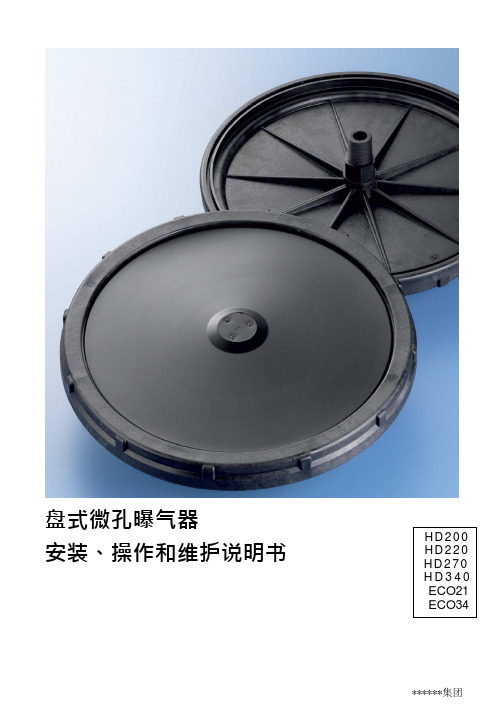
盘式微孔曝气器安装、操作和维护说明书H D 2 0 0 H D 2 2 0 H D 2 7 0 H D 3 4 0 ECO 21ECO 341曝气系统 (3)2概述 (3)3运输 (3)4到货检查 (3)5产品存贮 (3)6安装 (3)6.1准备工作 (3)6.2调节水平 (4)6.3曝气盘的安装 (4)7操作说明 (4)7.1安装 47.2标准操作 (4)7.3故障排除 (5)7.4保养和清理 (5)7.4.1保养 57.4.2机械清洗 (6)7.4.3化学清洗 (6)8更换 (6)9再循环 (6)10免责声明 (6)11参考文献 (6)1.曝气系统本手册详细说明了盘式微孔曝气器JetFlex HD 200、HD220、HD 270以及HD 340的安装和运行要求,也可作为HD 235、HD 325、ECO 21 和ECO 34的安装和操作指南。
2.概述******公司为市政和工业污水处理的曝气工艺提供曝气器。
曝气器为采用活性污泥工艺的污水处理厂提供微孔曝气,由于采用了特定配方的EPDM(三元乙丙)橡胶制造而成的膜片有较好的弹性,因此,可长期用于反硝化工艺间歇运行。
工业污水(生活污水中混有工业污水的量超过10%应当被定义为工业污水)可能需要使用其他的材料如硅橡胶、丁晴橡胶、氟橡胶或聚氨酯,请联系******公司。
从原料的混合到产品组装的每一个步骤,******公司都会严格控制,并可根据客户需要记录产品的一致性,所有的曝气器都在工厂完成组装。
曝气器在贮存、运输和安装时要小心处理避免损伤。
******公司的一般销售条件适用于曝气器产品的运输过程。
3.运输我们用厚纸板箱装运曝气器。
详情请查询包装信息。
4.到货检查根据交付的货物检查产品的包装,在装运时有结构损坏,特别是橡胶膜片。
包装、设备或产品的任何损坏都必须在交货起5个工作日内向******公司和运输公司通报。
******公司保留损坏检查的权利。
产品质保仅适用于采用原始且未损坏的包装情况。
软件系统运维手册

《软件系统运维手册》运维计划软件系统运维手册一、系统介绍本手册旨在为软件系统运维人员提供一个全面的指南,涵盖了系统安装、配置、运行、维护等方面的内容。
本手册适用于拥有软件系统运维需求的企业或组织,通过使用本手册,可以更好地管理和维护软件系统,提高系统的可靠性和稳定性,保障企业的正常运营。
二、系统架构本软件系统采用基于B/S架构的设计,主要由前端浏览器和后端服务器组成。
前端浏览器主要负责展示数据和用户交互,后端服务器则负责处理业务逻辑和数据存储。
系统采用分布式架构,包括数据层、业务逻辑层和表现层,以实现高可用性、高扩展性和高稳定性。
三、运行环境本软件系统需要运行在以下环境中:1.操作系统:Windows Server 2012 R2或CentOS 7.4及以上版本;2.Web服务器:Apache 2.4.18或Nginx 1.10.1及以上版本;3.数据库:MySQL 5.7.10或Oracle 12c及以上版本;4.浏览器:Chrome、Firefox、Safari或Edge等主流浏览器。
四、安装与配置本软件系统的安装与配置主要包括以下步骤:1.首先,根据操作系统要求准备一台服务器,并安装操作系统;2.然后,安装并配置Web服务器,如Apache或Nginx;3.接着,安装并配置数据库服务器,如MySQL或Oracle;4.最后,根据本手册提供的步骤安装并配置本软件系统。
五、用户管理本节将介绍如何进行用户管理,包括以下内容:1.用户创建:通过管理员账号创建其他用户账号,分配相应的权限;2.用户删除:删除不再需要的用户账号;3.用户权限管理:对用户账号的权限进行管理,如增删改查等操作;4.用户角色管理:对用户角色进行管理,如管理员、普通用户等;5.访问控制:对用户访问系统的权限进行控制,防止非法访问。
六、核心功能说明本节将介绍本软件系统的核心功能,包括以下内容:1.用户登录:用户通过输入用户名和密码进行登录;2.数据展示:展示数据表格、图表等数据可视化形式;3.数据查询:提供数据查询功能,支持条件查询和模糊查询;4.数据处理:对数据进行增删改查等操作;5.数据导出:将数据导出为Excel、CSV等格式;6.数据备份:对数据进行备份,防止数据丢失;7.系统管理:对系统进行设置、维护等操作。
产品安装、操作与维护手册说明书

I NSTALLATION,FAILURE TO FOLLOW THE INSTRUCTIONS ANDWARNINGS IN THE MANUAL MAY RESULT INSERIOUS OR FATAL INJURY AND/OR PROPERTYDAMAGE, AND WILL VOID THE PRODUCT WARRANTY. THIS PRODUCT MUST BE INSTALLED BY A LICENSED PROFESSIONAL. FOLLOW ALL APPLICABLE LOCAL AND STATE CODES AND REGULATIONS, IN THE ABSENCE OF SUCH CODES, FOLLOW THE CURRENT EDITIONS OF THE NATIONAL PLUMBING CODE AND NATIONAL ELECTRIC CODE,causing serious or fatal injury, leaking or flooding and/or property damage. To minimize risk, a licensed professional must install and periodically inspect and service the product. A drip pan connected to an adequate drain must be installed if leaking or flooding could cause property damage. Do not locate in an area where leaking could cause property damage to the area adjacent to the appliance or to lower floorssystem in this condition presents the risk of damageand leaks.Do not expose temperatures in excess of 140°F . Failure to properly size the product or follow these instructions may result in excessive strain on the system and may lead to product failure, serious or fatal personal injury, leakage and/or property damage. USE ONLY WITHworking pressure of 150 psig, whichever is less. At least once every 3 years or if discharge is present, a licensed professional should inspect the temperature and pressure relief valve and replace if corrosion is evident or the valve does not function. FAILURE TO INSPECT THIS VALVE AS DIRECTED COULD RESULT IN UNSAFE TEMPERATURE OR PRESSURE BUILD-UP WHICH CAN RESULT IN PRODUCT FAILURE, SERIOUS INJURY OR DEATH AND/OR SEVERE PROPERTY DAMAGEThe water quality canshould test for corrosive elements, acidity, total solids and other relevant contaminants, including chlorine and treat your water appropriately to insure satisfactory performance and prevent premature failure.NOTE: Inspect for shipping damage. Notify freight carrier or store where purchased immediately if damage is present. To avoid risk of personal injury and property damage, if the product appears to be malfunctioning or shows signs of corrosion, call a qualified professional immediately. Current copies of the product manual can be viewed at . Use proper safety equipment when installing.THIS IS THE SAFETY ALERT SYMBOL. IT IS USED TO ALERT YOU TO POTENTIAL PERSONAL INJURY AND OTHER HAZARDS. OBEY ALL SAFETY MESSAGES THAT FOLLOW THIS SYMBOL TO REDUCE THE RISK OF PERSONAL INJURY AS WELL AS PROPERTY DAMAGE.Model ST-1ApplicationThe ST-1 expansion tank is for use on tankless, residential on-demand water heaters with a total water content of 2 gallons or less and a maximum set point of 140°F. Do not use with larger storage-type water heaters, as these will exceed the capacity of the ST-1.Installation1. Install the expansion tank on the cold watersupply line to the water heater at a point between the water heater and backflow preventer or other one-way device (Figure 1).2. Once the expansion tank is installed, checkthe cold water supply line for any leakage.Make repairs if necessary.3. Before the initial firing of the water heater,open a hot water fixture and draw for one minute to purge air. Next, close and open the fixture in 30 second intervals, repeating three thimes to flush the tank and piping.Finally, turn the water heater temperature control to desired ending temperature (see water heater instructions). Do not set temperature higher than the expansion tank maximum.4. To relieve initial thermal expansion, slightlyopen a hot water faucet. Continue until water heater temperature is satisfied. Once heater is at its operating range, no further bleeding of expanded water is required.5. The water heater and expansion tank willnow be operational. The expansion tank will control pressure increases caused by thermal expansion to a level below the water heater relief valve setting. FOR USE ON TANKLESS RESIDENTIAL ON DEMAND WATER HEATERS WITH A TOTAL WATER CONTENT OF 2 GALLONS OR LESS ANDA MAXIMUM SET POINT OF 140° F. NON-ADJUSTABLE PRECHARGE.PSI Volume (cu.in.)Weight (lb.).000.00.8720.00 3.92 1.0140.00 5.77 1.0760.007.43 1.1380.008.17 1.16100.008.63 1.18120.009.00 1.19140.009.27 1.20150.009.27 1.20 MaintenanceA licensed professional should check the complete system, including the expansion tank, yearly and more frequently as the system ages. WarrantyST-1 Model: Seven (7) Year Limited Warranty Visit for complete warranty details.PLEASE READ THE FOLLOWING INSTRUCTIONS CAREFULLYI MPORTANT GENERAL SAFETY INFORMATION -ADDITIONAL SPECIFIC SAFETY ALERTS APPEAR IN THE FOLLOWING INSTRUCTIONS.1400 Division Road, West Warwick, RI 02893 USA T: 800.426.8765© 2020 Worthington Industries Inc. Part #: 9013-017 (01/21) One or more features of this product are covered by U.S. patents, visit /patents for more information.。
Nordson 总控制板 安装、操作和维护手册说明书
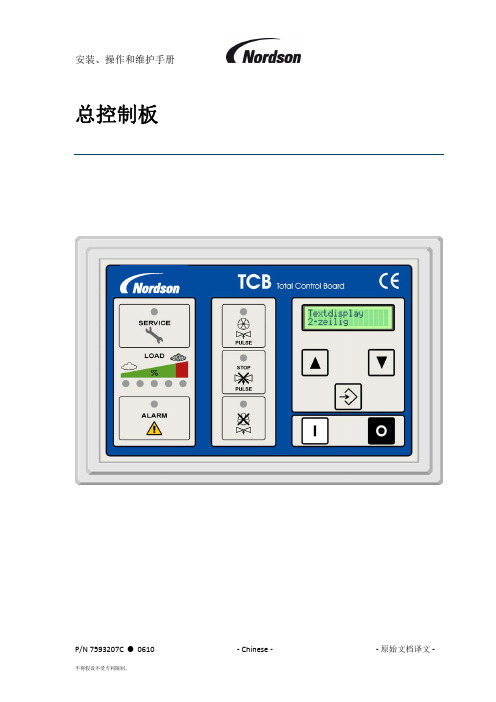
安装、操作和维护手册P/N 7593207C 0610 ‐ Chinese ‐ ‐ 原始文档译文 ‐总控制板重要请在安装前仔细阅读本手册阅读本手册时,应与辅助过滤器随附的相应产品手册和电路图结合使用目录1. 引言 52. 交货和安装说明 72.1. 外壳位置 72.2. 气动安装 73. 电气安装 83.1. 主开关 IP65 83.2. 马达连接 83.3. 电源电压:端子 1 和 2 93.4. RS-485 总线:端子 3-5 93.5. 马达保护:端子 25、28 93.6. 用于热敏电阻保护和/或爆炸隔膜的可选隔离放大器:端子 6-9 103.7. 风扇起动器的连接:端子 14–17(+ 12 和 13 用于 4 个 ECB 设备) 103.8. 警报继电器:端子 18-20 103.9. 远程启动/停止按钮:端子 21-23 103.10. 外部打开输入:端子 24、28 103.11. 遥控灯输出:端子 29-31 113.12. 可选模拟输出:端子 32-34 113.13. 阀输出:端子 V1–V16 – 单模块系统 113.14. 阀输出:端子 V1–V16 – 多模块系统 113.15. 旋转开关“从地址”和“模式”。
113.16. 可编程输入端 123.17. 可编程输出端 124. 预启动清单 155. 操作 155.1. 单风扇辅助过滤器系统 155.2. 多风扇设备(例如 ECB 设备) 155.3. 状态 LED 166. 使用菜单系统 176.1. 显示模式 176.2. 设置模式 177. 参数/内存字段说明 197.1. P00 设置 Pin 码 197.2. P02 Delta P 最小值 197.3. P03 Delta P 最大值 197.4. P04 Delta P 最大值报警 197.5. P05 低压报警 197.6. P06 脱机清洁周期 207.7. P07 星形/三角形切换时间 207.8. P09 清洁脉冲间隔 1 207.9. P12 清洁阀脉冲时间 207.10. P15 显示语言 207.11. P17 输入 I1 的功能(端子 26-28) 217.12. P18 输入 I2 的功能(端子 27-28) 217.13. P19 输出继电器 O1 的功能(继电器触点清洁功能开启/端子 10-11) 227.14. P20 可选输出继电器 O2 的功能(继电器触点开始为设备排气/端子 12-13) 227.15. P22 Delta P 清洁模式 237.16. P26 阀数量 237.17. P40 时间/日期显示 237.18. P41 设置时间与日期 237.19. P44 程序版本 247.20. P46 有效脉冲显示 247.21. P48 测试显示 247.22. P50 恢复为出厂设置 257.23. M05 总运行小时数 258. 报警消息和故障位置 269. 维护 2910. 选项和功能 2911. 技术规格 3012. 备件 3013. EC 一致性声明 3114. 联系地址 32图目录图1:TCB前面板 (6)图2:I/O模块PCB的端子视图 (9)图3:模块PCB接线图(细节) (10)图4:显示PCB电池 (29)1.引言根据《机械设备供应(安全)法规 1992 版》的要求,应提供完善的隔离设施和急停装置。
小型直流电机安装、运行和维护手册说明书

Installation, Operation and Maintenance ManualSmall DC Motors •56 Frames2Small DC MotorsReceiving and HandlingAcceptance Unpack motor carefully and inspect for possible damage during shipment.Check packing materials and save any instruction tags or wiring diagrams found in the carton. Report any damages or shortages immediately to the local transportation agent.Installation MountingCheck nameplate data on motor before installing to assure the correct rating and that the available power supply agrees with the required motor power supply.Motor should be mounted on a firm foundation.If the foundation is not flat, use shims to prevent misalignment when tightening hold-down bolts. DC motors arc equipped with ball bearings and may be operated in any position.For any position other than base down,new drain holes should be provided so that condensation is allowed to run off. Location should be dry, clean and well ventilated for most satisfactory service. Be sure the possibility of oil seepage into the motor is prevented. Commutator end of the motor should be accessible so that brushes can be conveniently inspected.Mounting Instructions for 56C & 140TC Face Mounted MotorsBefore mounting a “C”face motor to a mating flange,be sure both surfaces and all mounting holes are smooth and free of debris.When mounting into a quill type reducer, make sure the input and output shafts are coated with an anti-seize compound suitable for the application.!ATTENTION:Only qualified electrical personnel familiar with the construction and operation of this equipment and the hazards involved should install,adjust,operate,and/or service this motor.Read and understand this manual in its entirety before proceeding. Failure to observe this precaution could result in personal injury or loss of life.!ATTENTION:High voltage and rotating parts can cause serious or fatal injury. The use of electric machinery, like all other utilization of concentrated power and rotating equipment, can be hazardous. Installation, operation, and maintenance of electric machinery should be performed by qualified personnel.Familiarization with NEMA safety standards, national electrical code and sound local practices is recommended.!ATTENTION:To guard against personal injury or death causedby contact with moving parts, guards (coupling, belt, chain, etc.)must be installed. Machines accessible to the public should be further guarded by screening, guard rails, etc.Small DC Motors 3When mounting through a flexible coupling, verify that there is adequate clearance between the driven equipment shaft, the coupling interface and the motor ck of clearance may result in binding of the shafting and premature bearing failure.Always slide the motor tenon into the mating flange to its full depth before tightening the mounting bolts. Do not allow the motor to hang by the shaft extension while assembling it to the driven equipment (i.e. quill input gear case). This may bend or crease the shaft and damage any seals that are present.Only use the proper mounting bolts. These should be 3/8”-16 threads per inch and sized for length such that engagement into the motor flange does not exceed 9/16”. For example, a gear case with a 3/8” flange thickness requires a bolt that is: 3/8” + 9/16” = 15/16” = Maximum Bolt Length Since 15/16” is not a standard bolt length, a 7/8” bolt or a 1” bolt with a lockwasher can be used.AlignmentShafts should be carefully aligned before tightening any couplings. Inspect couplings and shaft for paint, dirt or burrs. If necessary, remove withsandpaper for proper fit. Pulley or coupling should be carefully fitted. Do not hammer on shaft, pulley or coupling.ApplicationPermanent Magnet “PM”motors are not always designed for across the line starting. This may cause loss of flux resulting in an increase in speed and possibly instability. Wound field motors can be started across the line with full applied voltage. However, for frequent starting or reversing, voltage should be reduced for normal brush and commutator life.Dynamic or regenerative braking methods should not be used unlessprovisions are made to limit the maximum instantaneous current to a value not greater than the maximum allowable peak amperes shown on the nameplate. This also applies to plug reversing the PM motor.ConnectionsAll motors should be installed in accordance with the National Electric Code and local requirements. Fuses, thermal cutouts and other protective devices should be the proper size and rating to safely carry the load and to interrupt the circuit on overloads.!ATTENTION:To guard against motor damage such aspremature failure and/or a loose assembly, use only mountingbolts that are the correct length.A bolt that is too long may cause damage to the motor.4Small DC MotorsConnection diagrams are shown above. Care must be taken to ensure that the dual-voltage shunt field is properly connected.Some DC motors are equipped with a thermostat inside the motor. This thermostat has a normally closed (NC) contact which opens if the motor temperature exceeds design limits due to extended overload operation.Leads from the thermostat are labeled P1& P2and should be connected in series with the drive “STOP” button (refer to the previous figure).!ATTENTION:Ground the machine properly to avoid seriousinjury to personnel. Grounding should be in accordance with theNational Electrical Code and consistent with sound local practices.+A1High Voltage Connection 1, 2Low Voltage Connection 1, 2High VoltageConnection1, 2LowVoltageConnection 1, 2Permanent Magnet Thermostat (if furnished)GroundConnection Connect in Series with Control Stop DeviceEarth Ground Series A2S1+F1F11F2A1+A2S1+F1F11F2+A1A2S1–S2+F1F11F2A1+A2S1+F1F11F2S2F22S2F22F22–S2F22+A1TypeS h u n t S t a b i l i z e d S h u n t a n d C o m p o u n d CCW Rotation Facing Commutator End CW –A2+F1F11–F2+A1A2S1S2A1+A2S1S2F22+A1–A2–A1–A1+A2+F1F11–F2F22+A1A2+F1F11F2F22–A1+A2+F1F11F2F22+A2P1P21Motors with single voltage fields do not have leads F11 & F22. Leads F11 & F22 may be marked F3 & F4, respectively. Connect on low voltage field connection.2Consult motor nameplate to determine value of low and high voltage connection.Small DC Motors5Important:When motors are provided with thermal protection (typicallythermostats), it is important to properly connect and apply thedevices. This will ensure that the motor is properly protectedfrom being operated if thermal limits are reached and/orexceeded.The control system must be configured to reduce themotor load and/or shut down the motor control system to allowthe motor to cool to a level within acceptable operating ranges.If the motor is operated with the thermal protective devicestripped (indicating an over temperature condition), the motorinsulation could be damaged and complete failure of the motorinsulation is possible. In the event of motor failure due to anover temperature condition,Rockwell Automation requires thatmotor thermal protective devices (when supplied) beadequately monitored and incorporated into the motor controlsystem to maintain warranty. Failure on the part of theindividual installing this equipment to take these steps willresult in the factory warranty being voided.OperationThese motors are inherently capable of operating over a wide range ofspeeds and loads. If the motor is not operated on the type of power supplyfor which it was designed, performance will differ from nameplate valuesand applicable standards.The motor should start quickly.If it fails to start,the load may be too great,the applied voltage too low, or the motor improperly connected and/or thecontrol misadjusted (check particularly current (torque) limit adjustment).In any case, immediately disconnect the power and investigate the cause.While operating the motor, observe the performance. Any undue noise,overheating, sparking or erratic performance should be investigated andnecessary corrective action taken to prevent serious damage.Maintenance The fundamental principle of electrical maintenance is keep the apparatusclean and dry.This requires periodic inspection of the motor,the frequencyof inspection depending upon the type of motor and the service.!ATTENTION:Internal parts of this motor may be at line voltage even when motor is not rotating. Disconnect all AC line connections before contacting any internal part.6Small DC MotorsBearingsBall bearings are deep grooved, double shielded with sufficient lubricantpacked into the bearings by the manufacturer for “life lubrication.” Theinitial lubricant is supplemented by a supply packed into larger reservoirs inthe end shield at time of assembly. No grease fittings are provided. Theinitial lubrication is adequate for up to 5 years of operation under normalconditions.Should it become necessary to replace bearings,the bearing bore and cavityshould be thoroughly cleaned and repacked with approximately 1/2teaspoonful of recommended grease.Bearings should be removed with bearing pullers using a center insert in theend of the shaft to protect the shaft center. To reinstall ball bearings, eitherin a press or on the bench, pressure should be applied to the inner race byusing a square faced sleeve or piece of pipe that will fit over the shaft, toavoid damaging the bearing. If a press is not available and a hammer isused,the blows should be transmitted against the sleeve by a block of woodor fiber.BrushesCheck brushes to make certain that they move freely in the holders andmake proper contact with the commutator. Re-place worn brushes. Givecomplete motor identification when ordering parts. New brushes should bepre-radiused to fit the commutator curvature. Blow out the carbon dust.Short brush life and poor commutation may be due to a rough commutator,a shorted armature, or poor undercutting of mica. Dirt and chemicals in theair are common causes of trouble.CommutatorThe commutator should remain a polished surface.Blackening may indicaterough or eccentric commutator. Occasional wiping (power off) with drycanvas or non-linting cloth may suffice. If rough or excessively dirty,smooth with very fine (00) sandpaper lightly with armature rotating. Neveruse emery cloth. Never allow the brushes to wear so short that springtension is lost. The resultant sparking will seriously damage thecommutator.If frequent dressing is required,the cause should be found and corrected.Avery rough commutator should be turned in a lathe, at high speed, with asharp tool.Do not remove more copper than necessary.The mica should beundercut if necessary.An authorized service shop is recommended for this work.Small DC Motors 7General The following should be checked at regular intervals:•Windings should be dry and free of dust, grease, oil, and dirt. Windings may be cleaned by suction cleaners or by wiping. Nozzles on suction type cleaners should be non-metallic.Gummy deposits of dirt and grease may be removed by using a commercially available low volatile solvent.Do not use gasoline or other inflammable solvents.•Terminal connections, assembly screws, bolts and nuts should be tight.They may loosen if motor is not securely bolted and tends to vibrate.•Insulation resistance of motors in service should be checked periodically at approximately the same temperature and humidity conditions to determine possible deterioration of the insulation. When such measurements at regular intervals indicate a wide variation, the cause should be determined. Motor should be reconditioned if the motor has been subjected to excessive moisture, or by rewinding or reinsulating if necessary. Enclosed motors require very little attention. Be sure that external air chamber of fan cooled motors does not become clogged with foreign material which will restrict passage of air.Troubleshooting If trouble develops in operation of motor, verify that:1.The bearings are in normal condition and have been properly lubricated with a high grade,ball bearing lubricant,free of dirt or grit.If dirt enters bearing, flush and relubricate.2.There is no mechanical misadjustment to prevent free rotation of moving parts of motor and drive.3.All bolts and nuts are properly tightened.4.Motor instructions have been carefully carried out.5.The rated voltage is available at the motor terminals.6.The voltage corresponds to the value stamped on the nameplate.7.All connections are properly made in all circuits between motor and control.8.The overload and low voltage devices in control equipment, fuses or other protective devices are in proper working order.9.Brushes are in good condition and are making good con-tact with the commutator.10.The commutator is clean and has smooth polished surface.11.No excessive overload exists on the pare line amperes at full load with nameplate stamping.!ATTENTION:Internal parts of this motor may be at line voltage even when motor is not rotating. Disconnect all AC line connections before contacting any internal part.Online DocumentationThe latest motor information can be obtained from the Allen-BradleyDrives & Motors home page on the World Wide Web at:Publication1325R-UM001B-EN-P Ð A ugust, 2001Supersedes 1325R-UM001A-EN-P dated May, 2001Copyright © 2001 Rockwell Automation. All rights reserved. Printed in USA.。
安装操作维护手册
安装、操作维护手册(用户指南)目录1联轴器说明2操作条件和极限3一般注释4安装说明5安装对中说明6常见异常工况和罕见异常工况时可采取的预防措施7维护说明8安装说明图纸9联系详细信息正文1.联轴器说明Euroflex联轴器是一种多层膜片挠性联轴器,通过多层组合的膜片的变形而获得挠性。
这些膜片组由一个或多个中间接筒隔成多个膜片组。
膜片组能承受的轴向和角度方向的变形量和不对中量有极限值限制。
这些极限值是对这种联轴器所规定的。
要十分小心,别超过这些极限值。
单个膜片常常有多边形外形,这些构成特定厚度的膜片组的膜片通过衬套来固定。
在螺栓孔中心处,螺栓穿过衬套孔,衬套穿过膜片组的孔来连接驱动机端和被驱动机端半联轴节,并传输扭矩和挠性。
螺栓、衬套和相应的孔应按较小的公差制造。
然而,由于实际组装的需要,衬套和螺栓与孔的配合应是间隙配合。
为了补偿这个间隙,和保证与膜片组相邻的零件保持同心,应使法兰螺栓孔中心直径比膜片组螺栓孔中心直径稍大。
这样膜片组在组装后就稍微“拉紧”。
组件上的螺栓上紧到相对紧的程度,以产生巨大的预紧载荷。
这一预紧载荷对于避免在工作的情况下螺纹旋合面发生的滑丝,或对于消除由于传输扭矩产生的外伸力拒所导致的螺栓弯曲等有着重要的作用。
这样上紧螺栓被认为是相当重要的。
通常这种设计原理在许多已投用的装置上都得到了证实。
2. 操作条件和极限在工作的情况下,膜片组承受由于扭矩,转速和不对中所造成的巨大拉伸和弯曲应力。
这些应力都与其中一种应力影响另一种应力的许用极限的程度大小的变化相关联。
在正常情况下,扭矩随转速而变化。
这种变化关系的重点在于不对中的程度。
正因为如此,轴向挠曲的程度的变化将改变角度不对中的允许程度。
因此,在所有的操作条件下,联轴节上的不对中量应维持在最终设计数据所陈述的最大允许值以内,这一点非常重要。
初始不对中量应尽可能精确,并应维持在本文的对中和\或安装说明章节上给定的对中极限值以内。
在机器操作期间,允许(正常或事故状态下的)更大位移时的初始极限值应尽可能的低。
惠普 HP7000 风扇 安装、操作和维护 用户手册说明书
2订单号__________________________________________试验倾斜角度____________________________________最终倾斜角度____________________________________转速____________________________________________额定马力________________________________________ 风扇组件52102 钢毂板 110 工具包 - 叶片螺栓 111 叶片螺栓 120 工具包 - 中心钢毂盘五金件 121 帽螺栓 5/8 英寸 122 平面垫圈 5/8 英寸 123 卸扣 1/2 英寸 130 工具包 - 叶片螺栓五金件 131 机制螺栓 3/4 英寸 132 平面垫圈 3/4 英寸 133 六角自锁螺母 3/4 英寸或 六角螺母 3/4 英寸和自锁垫圈 3/4 英寸 134 螺纹脂 140 工具包 - 钢毂盘盖五金件 141 机制螺栓 3/8 英寸 142 平面垫圈 3/8 英寸 143 自锁垫圈 3/8 英寸 144 六角螺母 3/8 英寸 145 六角自锁螺母 3/8 英寸 146 垫片 150 工具包 - 平衡五金件 160 手册 170 工具包 - 钢毂盘支架 1930 毫米钢毂盘装配的必需配置 171 钢毂盘支架 172 机制螺栓 1/2 英寸 173 平面垫圈 1/2 英寸 174 六角自锁螺母 1/2 英寸200 叶片300 钢毂盘盖 图 1 - 典型风扇装配实际组件外观可能有所不同3➠注风扇钢毂盘安装以下指示信息详细说明在 Marl ey Geareducer ® 上安装 Marl ey HP7000 风扇的过程,该风扇配有使用带螺栓的风扇钢毂盘固定板的锥形风扇(输出)轴承或使用锥形分离轴衬的直叶式风扇轴承。
其他减速设备的安装可能有所不同。
HMDS磁选机安装调试,运行和维护保养手册
HMDS-914×2972磁选机安装调试,运行和维护保养手册(合资)抚顺隆基磁电设备有限公司目录1.注意事项2.工作原理及特点3.润滑4.安装、调试及运行5.操作、维护与安全6.易损件表一、注意事项为确保您的人身、设备及财产的安全,在使用设备之前,请您务必阅读使用说明,并在以后的搬运、安装、运行、调试与检修过程中遵照执行。
1、安全注意事项(1)使用前请仔细阅读说明书并请遵照其注意事项。
(2)佩带起搏器或类似医用电子设施的人群禁止靠近磁选机。
2、使用注意事项;(1)检查清除所有料箱中的杂物,尤其是滚筒和料箱之间。
铁质物件一旦进入槽体和滚筒之间,清除的难度很大,因此安装调试直到正常运行期间,一定要采取措施防止杂物落入。
(2)每三个月左右定期加注润滑油。
(3)每一个班次停止工作后清理进料箱、槽体以及排粗机构中的杂物。
二、工作原理及特点1、概述HMDS型磁选机适用于矿山、选煤厂等单位,用于弱磁场湿式选别细颗粒的强磁性矿物,或者除去非磁性矿物中混杂的强磁性矿物。
如回收重介质选矿中的磁性重介质加重剂,铁选矿厂中低浓度矿浆的浓缩和磁铁矿物的富集,处理强磁选机的给矿,清除其中的磁性或较弱磁性矿物及其连生体,防止磁介质堵塞。
HMDS型磁选机采用计算机优化设计,磁路合理并严格选用高矫顽力,高剩磁的永磁体,确保磁性在长时间内不降低,所以处理矿浆体积量大,磁性铁回收率高,再选后的尾矿一般再无回收价值。
选到精矿中非磁性矿物夹杂少,精矿品位可调整,矿浆浓缩或不浓缩皆可入选。
使用中操作简单,管理方便。
保障用户的长远利益,整体结构可靠耐用。
2、工作原理逆流槽型磁选机适用于粒度0.6~0毫米强磁性矿物的湿式粗选和扫选,可获得粗精矿和尾矿两种产品。
矿浆由给矿箱均匀地给入槽体,在分选空间入口处,有特殊的弧形凸起,以使不同矿粒能在分选空间中沿整个给矿宽度上均匀分布,充分悬浮,使流动方向与磁力方向一致,有利于圆筒充分吸引磁性物.磁性较强的矿物受磁力作用,被吸附于圆筒表面,随圆筒旋转带磁性区,在重力和旋转抛力下流入精矿槽,非磁性物由溢流口排出,溢流堰具有一定高度保证圆筒在矿浆中在一定的浸入深度,这是由结构而定,不需象顺流槽那样人为控制溢流。
NX 冷却塔 安装 - 运行 - 维护 用户手册说明书
2 目录本手册包含正确安装和运行冷却塔的重要信息。
安装和运行冷却塔前请仔细阅读手册,然后按照所有说明运行。
请保存本手册,以便将来参考。
概貌 ............................................................................................................................. 3安全 ............................................................................................................................. 3冷却塔运输....................................................................................................... 4接收冷却塔 ............................................................................................................... 4冷却塔位置 ............................................................................................................... 4冷却塔装配 ............................................................................................................... 5马达接线 .................................................................................................................... 6机械设备 .................................................................................................................... 6冷却塔启动 ............................................................................................................... 7水质和排污 ............................................................................................................... 12冷却塔维护进度 ...................................................................................................... 13冷却塔维护 ............................................................................................................... 18季节性停机说明 ...................................................................................................... 19 延长停机 .................................................................................................................... 20附加信息 .................................................................................................................... 20故障检查及修理 ...................................................................................................... 22下列定义的术语将在整本手册中使用,请注意各级风险和有关系到产品寿命的重要信息。