茂捷M8918替换BP2328资料
捷瑞电讯设备2108 RS485中继器用户手册说明书
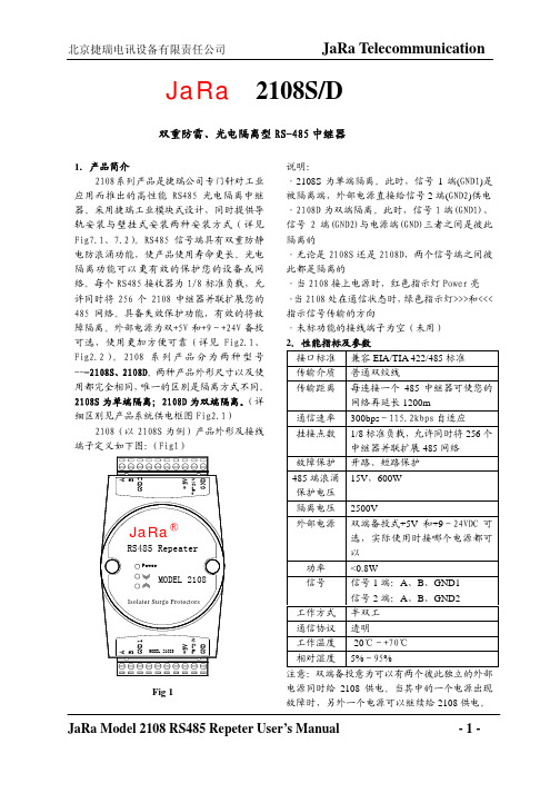
JaRa 2108S/D双重防雷、光电隔离型RS-485中继器Fig 11.产品简介2108系列产品是捷瑞公司专门针对工业应用而推出的高性能RS485光电隔离中继器。
采用捷瑞工业模块式设计,同时提供导轨安装与壁挂式安装两种安装方式(详见Fig7.1、7.2)。
RS485信号端具有双重防静电防浪涌功能,使产品使用寿命更长。
光电隔离功能可以更有效的保护您的设备或网络。
每个RS485接收器为1/8标准负载,允许同时将256个2108中继器并联扩展您的485网络。
具备失效保护功能,有效的将故障隔离。
外部电源为双+5V 和+9~+24V 备投--说明:·2108S 为单端隔离。
此时,信号1端(GND1)是被隔离端,外部电源直接给信号2端(GND2)供电·2108D 为双端隔离。
此时,信号1端(GND1)、信号2端(GND2)与电源端(GND)三者之间是彼此隔离的·无论是2108S 还是2108D,两个信号端之间彼此都是隔离的·当2108接上电源时,红色指示灯Power 亮 ·当2108处在通信状态时,绿色指示灯>>>和<<<指示信号传输的方向·未标功能的接线端子为空(未用) 电源同时给2108供电。
当其中的一个电源出现故障时,另外一个电源可以继续给2108供电。
3.2108S/D隔离方式下图为2108S/D的系统供电框图(Fig 2.1为2108S,Fig 2.2为2108D)Fig 2.1 Fig 2.2说明:2108S为单端隔离(隔离信号1端),2108D为双端隔离(信号1端和信号2端都隔离)。
即:2108S的电源与信号端2是非隔离的,而与信号端1是隔离的(如图Fig2.1所示,)。
2108D的电源端与信号1端和2端彼此之间都是隔离的。
可以用万用表验证2108S/D的隔离方式。
将万用表拨到短路档,分别测量GND、GND1和GND2三个地之间的短路情况。
rs232转ttl

RS232转TTL什么是RS232和TTL?RS232和TTL都是串行通信协议,用于在电子设备之间传输数据。
RS232是一种标准的串行通信协议,通常用于计算机和外围设备之间的通信,如调制解调器、打印机等。
而TTL (Transistor-Transistor Logic)是一种数电门电平的传输方式,通常用于逻辑芯片之间的通信。
为什么需要RS232转TTL?RS232和TTL的电平标准并不兼容,因此在两者之间进行通信时需要进行电平的转换。
在某些应用中,需要将RS232信号转换为TTL信号,这时就需要使用RS232转TTL模块。
RS232转TTL模块的工作原理RS232转TTL模块通过电路将RS232串口信号转换为TTL 电平信号。
通常,RS232信号的电压范围是-15V至15V,而TTL信号的电压范围是0V至5V。
因此,RS232串口信号需要被转换为TTL电平信号,以便与TTL电平设备进行通信。
RS232转TTL模块的电路设计通常采用电平转换芯片,如MAX232。
这种芯片能够将RS232信号的电平转换为TTL电平,并提供逻辑级别的转换。
通过使用MAX232芯片,RS232信号可以被转换为适用于TTL设备的信号。
RS232转TTL模块的应用场景RS232转TTL模块广泛应用于嵌入式系统、工业自动化、通信设备等领域。
以下是一些常见的应用场景:1.嵌入式开发:在很多嵌入式系统中,需要与计算机进行通信。
由于计算机通常使用RS232接口进行通信,因此需要使用RS232转TTL模块将串口信号转换为适用于嵌入式系统的TTL电平信号。
2.工业自动化:在许多工业自动化应用中,需要与各种设备进行数据传输。
由于一些设备使用RS232接口,而另一些设备使用TTL接口,因此需要使用RS232转TTL 模块进行电平转换,以实现设备之间的数据通信。
3.通信设备:在一些通信设备中,需要与其他设备进行数据传输。
由于不同设备间通信接口不同,因此需要使用RS232转TTL模块,以实现不同设备之间的通信。
ARB-0612 USB转RS232 422 485 485-4W TTL转换器手册说明书
ARB-0612Converter USB – RS 232/422/485/485-4W/TTLManualARB-0612_v1_01Update date:10/2018r.Symbols & Marks (3)General installation and safety rules (3)1.Destination of device (4)2.Device parameters (5)2.1.Technical parameters (5)2.2.Description of connectors (6)2.3.Block diagram (8)2.4.Dimensions (8)3.Wiring (9)4.Instalation (10)4.1.Installation of USB drivers (10)4.2.Changing the COM port assignment in Windows (11)4.3.Exploitation (14)5.Contact details (14)General installation and safety rulesThe device should be installed in accordance with this manual.The fulfillment of this condition is the basis for ensuring safety and correct operation of the device. The fulfillment of this condition is the basis for ensuring safety and correct operation of the device.The manufacturer is not liable for damages resulting from using the device in the wrong way or not according to the purpose.Modifications to the device are not allowed and can be a source of danger.The ARB-0612 converter converts the USB signal into a serial communication standard RS232/RS422/RS485,RS485-4W/TTL-3.3,TTL-5V. The device is powered directly from the USB port. The converter supports two RS485 standards (2-wire and 4-wire), can act as HUB USB to 2xRS485 2-wire.Works with32 and 64bit operating systems.Remember to use the appropriate drivers. The device is intended for the USB 2.0 standard. When connected to the 3.0 standard, the converter works as if it was connected to the standard 2.0. It is possible to choose one of four serial transmission standards, i.e. RS232, RS422, RS485 or TTL. The converter provides 1500V, 2500V, 3000V or 5000V isolation between the USB port and the other serial ports. In addition, the RS422 and RS485 port has overvoltage protection. The operating system creates a virtual COM serial port that can be used by applications as an ordinary COM port. The user has the option of assigning a different COM port number than the one that automatically assigned the system. All parameters of the COM port (for example: baudrate, parity check), are determined by the application using the converter ARB-0612.Application:–Protecting your PC or laptop from overvoltages and from damage that may occur when using serial communications.–Creating or adding an additional serial port from 1 to 256.–The RS232 port is equipped with all transmission and reception lines, which allows for safe programming of controllers and other devices requiring serial communication and using additional RS232 port signals.–The ARB-0612 converter has an internal reset signal, thus it can be used for permanent operation in applications that have the option of automatically rebuilding the serial port.2.1.Technical parametersTechnical parameters of the converter are presented in Table 2.1.1.2.2.Description of connectorsThe view of the ARB-0612 converter is shown in Figure 2.2.1. A description of its connectors is presented in Table 2.2.1. A description of the function of connectors, DB9 sockets, dip-switch and LED indicators is presented in Table 2.2.2.Fig. 2.2.1. View of the converter ARB-0612Male socket- A denotes the D + line, B denotes the D - line.** - switch operations must be carried out in pairs.*** - OFF position - active RS485; ON position - active RS422 / RS485-4W.The block diagram of the ARB-0612 converter is shown in Figure 2.3.1.Fig. 2.3.1. Block diagram of ARB-06122.4.DimensionsDimensions of the ARB-0612 converter are shown in Figure 2.4.1.Fig. 2.4.1. Dimensions of the ARB-0612Table 2.5.1 presents the available versions with catalog numbers.3.WiringThe device should be connected to a computer using a USB cable. One of the selected RS232, RS422, RS485, RS485-4W or TTL ports should be selected. The method of connecting the RS port is shown in Figure 3.1.USB/RS422,485-4W USB/RS232USB/TTLPołączenie Null Modem3-TxD2-RxD5-GND*opis połączenia null modem wtab. 3.1Fig. 3.1. The method of connecting the RS ports.4.Instalation4.1.Installation of USB driversBefore you start the proper operation, you must install the appropriate USB drivers on the computer with which the converter should work. The type of drivers depends on the operating system installed on your computer.The drivers and instructions for installing them are available at: /FTDrivers.htm.To change the assignment of the COM port, it is necessary to start the Device Manager while the converter ARB-0612is connected from the USB side to the computer.Menu: Start->Control Panel->System->Hardware->Device ManagerSelect USB Serial Port whose settings you want to change.Press the right mouse button and select Properties from the expanded menu.In the Port Settings tab, please select Advanced options ...In case the selected port is already occupied by another device,the following message will appear:If you have to use this port, press YES4.3.ExploitationAfter correct installation of the drivers and connecting the converter to the USB port in the device manager should be visible COM port assigned to the converter. The device is signaled by sound and blinking of DL and UL diodes. The PWR diode should be permanently illuminated.5.Contact detailsASPAR s.c.ul. Oliwska 112,80-209 Chwaszczyno, POLANDphone +48 58 351-39-89; +48 58 732-71-73****************www.ampero.eu。
捷瑞 2103A B C 双重防雷、光电隔离型 RS-232 RS422 485 接口转换器 使用说

JaRa® MODEL 2103A/B/C双重防雷、光电隔离型RS-232ÙRS422/485接口转换器使用说明书1.产品简介捷瑞2103系列产品是专门针对工业应用而设计的高性能双向转换器,在232端、422/485端和电源端进行三端隔离保护,并增加了浪涌保护功能。
采用亚当模块式设计,易于安装在工业导轨上。
RS422/485端具有双重防静电防浪涌功能。
捷瑞2103系列将RS-232信号透明的转换成RS-422和RS-485信号,无需改动连接设备的软硬件,轻松使232设备接入RS-422/485网络,组建工业级的远距离通信系统。
2103系列产品分为3种型号---2103A、2103B、2103C。
三种产品外形尺寸以及使用方法都完全相同,唯一的区别是隔离方式不同:2103A为隔离RS232端;2103B为隔离RS422/485端;2103C为RS232端、RS422/485端和电源端三端全隔离。
2.2103A/B/C外形及引脚定义注意:2103A/B/C的RS422与RS485共用同一个信号地(SG)3.性能参数接口标准 兼容EIA/TIA的RS232C 、RS422/485标准传输介质 普通双绞线传输距离 0---1.2Km通信速率 300---115.2Kbps挂接点数 32个标准节点隔离电压 连续2500V 瞬间7500V 浪涌防雷 600W供电方式 在接线柱的VPP 和GND 之间接+9VDC~+24VDC直流电源 信号RS-232: RXD、TXD、GND RS-485:A、B、SG(可选)RS-422:T+、T-、R+、R-、SG(可选) 工作方式 RS-485 时为半双工,RS-422方式时全双工, 通信协议 透明流控 无须RTS/CTS 硬件流控和软件控制,智能转换(自动流控) 环境工作温度-10℃---50℃ 相对湿度5%---95%备注:2103A/B/C 的RS232信号DTR 与DSR, RTS 和CTS 已经内部短接,DCD 和RI 内部悬空未用2103A/B/C 具有RS422和RS485自动识别功能。
CANCOM-100IE+智能转换器 RS232 485 422 转 CAN-bus 用户手册说明书

CANCOM-100IE+智能转换器RS232/485/422转CAN-bus修订历史目录1. 功能简介 (1)1.1概述 (1)1.2产品特性 (1)1.3典型应用 (1)2. 硬件描述 (2)2.1产品外观 (2)2.2接口描述 (2)2.2.1RS-232接口引脚定义 (2)2.2.2接口定义 (3)2.3指示灯说明 (3)2.4CAN总线连接 (4)3. 配置说明 (5)3.1配置方式进入 (5)3.2软件说明 (5)3.2.1转换参数 (6)3.2.2串口参数 (7)3.2.3CAN参数 (7)3.2.4举例介绍验收滤波的设置 (8)3.2.5按键说明 (9)4. 转换示例 (10)4.1透明转换 (10)4.1.1帧格式 (11)4.1.2转换方式 (11)4.1.3转换示例 (12)4.2透明带标识转换 (13)4.2.1帧格式 (13)4.2.2转换方式 (14)4.2.3转换示例 (15)4.3格式转换 (16)4.4Modbus转换 (18)4.4.1帧格式 (18)4.4.2转换方式 (19)4.4.3转换示例 (20)5. 设备固件升级 (22)6. 设备测试 (24)6.1设备准备 (24)6.2通讯测试 (24)7. 安装尺寸 (25)8. 免责声明 (26)1. 功能简介1.1 概述CANCOM-100IE+ 智能协议转换器可以快速将RS-232/485/422通讯设备连接CAN-bus 现场总线。
转换器支持600~230400bps速率,5Kbps~1Mbps的CAN-bus通讯速率。
转换器提供四种数据转换模式:透明转换、透明带标识转换,格式转换,Modbus转换(Modbus转换功能仅在CAN总线设备报文可编辑的情况下可以使用)。
CANCOM-100IE+转换器提供配置软件,可以灵活设置CANCOM-100IE+的运行参数。
1.2 产品特性●实现CAN-bus与RS-232/485/422的双向数据通讯;●支持CAN2.0A 和CAN2.0B 协议,符合ISO/DIS 11898规范;●集成1路CAN-bus通讯接口,支持用户自定义的通讯波特率;●CANCOM-100IE+集成1路3线式RS-232通讯接口,集成1路2线式RS-485通讯接口,集成1路4线式RS-422通讯接口,通讯速率在600~230400bps之间可设定;●提供四种数据转换模式:透明转换、透明带标识转换,格式转换,Modbus转换;●支持CAN-bus虚拟PC串口应用;●CAN-bus电路采用DC 2500V电气隔离;●可以用在有安全防爆需求的环境中(*);●工作温度:-40℃~+85℃,工作功率:低于2W。
捷瑞电讯设备2108 RS485中继器使用说明书

JaRa 2108S/D双重防雷、光电隔离型RS-485中继器产品使用说明书1.产品简介2108系列产品是捷瑞公司专门针对工业应用而推出的高性能RS485光电隔离中继器。
采用亚当模块式设计,易于安装。
RS485端具有双重防静电防浪涌功能。
2108系列产品分为2种型号---2108S、2108D。
两种种产品外形尺寸以及使用都完全相同,唯一的区别是隔离方式不同。
2108S为单端隔离;2108D为双端隔离。
(详细区别见产品系统供电框图)2.2108S/D外形及引脚定义(注意:图中NC表示“未用”)说明:2108S为单端隔离。
此时,SG2与GND是同一个地。
但,与SG1不是同一个地2108D为双端隔离。
此时,SG1、SG2、GND三者不是同一个地2108S/D接上电源时,电源指示灯Power(红色)长亮当有数据由左向右传输时,指示灯>>>(绿色)闪烁当有数据由右向左传输时,指示灯<<<(绿色)闪烁3.性能参数接口标准 兼容EIA/TIA的RS485标准传输介质 普通双绞线传输距离 单端0---1.2Km,双端2400m,可使您的485网络再延长1200m通信速率 300---115.2Kbps挂接点数 32个标准节点隔离电压 2500V供电方式 在接线柱的VPP和GND之间接+9VDC~+24VDC直流电源信号 SG1端:A、B、SG1(可选);SG2端:A、B、SG2(可选)工作方式 半双工通信协议 透明工作温度 -10℃---50℃相对湿度 5%---95%备注:2108S/D的外部供电电源设计为可以从两端提供,既,将+9VDC~+24VDC直流电源接在2108S/D的任何一端都可以。
两端的电源地(GND)是相通的,但两端的电源VPP是不通的。
详细情况参见2108S/D的内部供电框图4.2108S/D的内部电源供电框图4.1 2108S(单端隔离)(注意:2108S的SG1端485的信号地(SG1)与电源地(GND)是同一个地)4.2 2108D(双端隔离)(注意:2108D的右信号地SG1、信号地SG2与电源地(GND)彼此不是同一个地)5.应用举例5.1 2108S/D并联方式扩展RS-485网络说明:并联2108S/D方式用于在同一个区域内扩展您的485通信网络,增加您的485网络的设备数量。
USB-8COMi-M USB转八口RS-422 485转换器用户手册说明书
Introduction of USB-8COMi-MThe USB to industrial Octal RS-422/485 Adapter is designed to make serial port expansion quick and simple. Connecting to a USB port on your computer or USB hub, the USB Serial Adapter instantly adds 8 RS-422/485 multi-electrical interface serial communication ports to your system. By taking advantage of the USB bus, the USB-8COMi-M Adapter makes it easier than ever to add 8 RS-422/485 ports and serial devices to your system with easy plug-and-play and hot plug features. Adapting the new technology, the serial port expansion now takes the new bus with easy and convenient connectivity.Plugging the USB 8-Port RS-422/485 Adapter to the USB port, the adapter is automatically detected and installed. There are no IRQ & COM port conflicts, since the port doesn't require any additional IRQ, DMA, memory as resources on the system. The RS-422/485 port functions as native Windows COM port, and it is compatible with Windows serial communication applications. Each port is individually configurable. The adapter is designed with external switches to set the RS-422 or RS-485 ports and different operation modes conveniently. There is no need to open the chassis to set the ports.The USB Serial Adapter provides instant connectivity to RS-422 or RS-485 communication devices for factory automation equipment, multi-drop data collection devices, barcode readers, time clocks, scales, data entry terminals, ATMs and serial communication in harsh environment. The USB to Serial Adapter is suitable for remote access, retail and industrial application, data collection and other applications requiring high speed RS-422/485, communication ports. Specifications & Features●Adds eight high speed RS-422 / 485 serial ports via USB connection.●384 byte receive buffer.●128 byte transmit buffer for high speed data throughput.●Requires no IRQ, DMA, I/O port.●Data rates: 300 bps to 921.6K bps.●Serial Connector: one DB-9 male connector.●Auto transmit buffer control for 2-wire RS-485 half-duplex operation.●Termination resistors installed on-board.●RS-422 data signals: Tx-, Tx+, Rx+, Rx-, GND, RTS-, RTS+, CTS+, CTS-.●RS-485 data signals: Tx-, Tx+, Rx+, Rx-(4 wire) and data-, data+ (2 wire).●Monitor LEDs of TxD, RxD indicating port status.●Power Supply: provides an external DC12V power adapter●Virtual COM port drivers available for Windows 7, Vista, 2003, XP, 2000.Hardware InstallationOutside the unit, there are eight 3-pin DIP switches which are set to select the mode of operation. You will need to set the switch settings to RS-422 or RS-485 mode as per the requirements of your application.You need to install driver first, prior to hardware installation. After the setting of DIP switches and connecting power cord to the adapter, you then plug the adapter to USB port to start driver installation.The Mode Block Configuration Settings are listed as follows:SW1 (Port-1), SW2 (Port-2), SW3 (Port-3), SW4 (Port-4)SW5 (Port-5), SW6 (Port-6), SW7 (Port-7), SW8 (Port-8)JP3 (Port-1), JP4 (Port-2), JP5 (Port-3), JP6 (Port-4)JP7 (Port-5), JP8 (Port-6), JP9 (Port-7), JP10 (Port-8)for Termination and Biasing Option ConfigurationInside the unit, there are eight 2 x 7 (14 pin) header blocks which are jumpered to enable Tx, Rx, CTS 120 Ohm termination resistors and Tx, Rx 750 Ohm BIASing resistor.You will need to open up the metal case and set the jumper setting for RS-422 mode or RS-485 mode as per the requirements of your application.Settings are listed as follows:Note: Sometimes, when operating in RS-422 or RS-485, it is necessary to configure termination and biasing of the data transmission lines. Generally this must be done in the cabling, since this depends on the installation of connections. Before applying the option, check your cable specification for proper impedance matching.You need to have administrator privileges to install any new drivers under Windows 7/ Vista / 2003 / XP / 2000. To install the driver or update the configuration please log onto Windows as "Administrator" or ask your system administrator to install the USB-COM driver.You need to install driver first, prior to hardware installation. Do not connect the USB-to-Serial Adapter to the USB port of your computer, before you finish driver installation.Please proceed with the following steps to install the driver:1. Insert the “USB COM Series Driver and Utility” CD into your CD-ROM.2. The “USB COM Series Driver and Utility CD” dialog box appears.3. Under “Driver Installation”, double click “Windows 7, Vista, 2003, XP, 2000driver” to install the device driver.4. The USB COM install program will auto-detect the OS type and install thedriver automatically. (Note: in Windows 7 or Vista OS you will find anotherdialog box, please click on “OK” to confirm the drivers install program).5. After the message “FTDI CDM Driver installation process completed”appears, press “Enter” to complete the driver installation.6. Plug in the USB to Serial Adapter to the USB port of your computer.Windows will finish installing the driver files.Check InstallationYou can now verify the installation has been completed successfully by looking under Device Manager of the System Properties screen. (Go there by Start-Setting- Control Panel-System Properties-Hardware-Device Manager.The device should have installed as a "USB Serial Port (COMx)" attached to "USB Serial Converter A/B/C/D".Change COM Port Properties & COM Port NumberThis feature is particularly useful for programs, such as HyperTerminal, which only work with COM1 through COM4. Please ensure that you do not change the COM Port Number already in use.To change the virtual COM port properties:●Select the "USB Serial Port"●Click “Properties”.●Select "Port Setting" and “Advanced”.●Click the drop down arrow on COM Port Number and scroll to the required COMport. Select "OK".●Return to the Device Manager Screen. You will see that the USB Serial Portinstallation has been changed to the new COM Port Number.Uninstalling Windows 2003/XP/2000 DriversPlease proceed with the following steps to uninstall the 2003/XP/2000 driver:1. Insert the “USB COM Series Driver and Utility” CD into your CD-ROM.2. The “USB COM Series Driver and Utility CD” dialog box appears.3. Under “Driver Uninstalling”, double click “Windows 2003, XP, 2000 driveruninstall” to uninstall the device driver.4. When following dialog box appears, double click “Clean System” touninstall the 2003/XP/2000 drivers.5. You need to disconnect all USB to serial Adapters from your PC, when themessage below appears. Double click “OK” to start uninstalling Windows2003/XP/2000 USB to Serial drivers.6. Double click “Yes” to confirm it.7. Click “No” to proceed.8. When the message “Status: System clean completed” appears, double click“Exit” to complete the USB to serial drivers uninstall.9. Press “Start” button and select “Control Panel”.10. Open the Add or Remove program.11. Remove the first “Windows Driver Package – FTDI CDM Driver Package (…)”.12. Click “Chang/Remove” and “Yes” to remove the first Windows DriverPackage.13. Remove the second “Windows Driver Package – FTDI CDM Driver Package(…)”.14. Click “Chang/Remove” and “Yes” to remove the second Windows DriverPackage.15. Reboot the computer to complete the driver uninstall.Uninstalling Windows 7 or Vista DriversWindows 7 and Vista have many new security features. You need to proceed with the following steps to uninstall the Vista driver:1. The USB to serial devices must connect to the PC.2. Press “Start” button and select “Control Panel”.3. Select “Classic View” from the top left hand corner and then “System” fromthe list.4. Select “Device Manager” from the top left hand corner.5. Locate your Device under the Ports (COM & LTP) section and right click onit to bring up the menu shown.Note: if you have more than one USB Serial Port (COMx) installed in your PC, you need to repeat from step 5 to step 6 to delete the driver software for each port.7. Locate your Device under the Universal Serial Bus Controllers section, andright click on it to bring up the menu shown.Note: if you have more than one USB Serial Converter installed in your PC, you need to repeat step 7 and step 8 to delete the driver software for all devices.RS-422 Signal Pin-outs of DB-9 MaleRS-422 Signal Wiring● Point- to- Point 4 Wire Full Duplex● RS-422 with Handshaking2 TxD+(B) RxD+ (B) RxD- (A) TxD+(B) TxD- (A) GND USB-8COMi-M RS-422 Device1 TxD- (A) 3 RxD+ (B) RxD- (A) 5 GND 7 RTS+(B) CTS+(B) 6 RTS- (A) CTS- (A) 8 CTS+(B) RTS+(B) 9 CTS- (A)RTS- (A)4 2 TxD+(B) RxD+ (B) RxD- (A) TxD+(B) TxD- (A)GNDUSB-8COMi-M RS-422 Device 1 TxD- (A) 3 RxD+ (B) RxD- (A)5 GND 4RS-485 4-Wire (Full duplex) Signal Pin-outs of DB-9 MaleRS-485 2-Wire (Half duplex) Signal Pin-outs of DB-9 MaleRS-485 Signal WiringPoint-to-Point 4-Wire Full Duplex2 TxD+(B) RxD+ (B)RxD- (A) TxD+(B) TxD- (A) GNDUSB-8COMi-M RS-485 Device1 TxD- (A) 3 RxD+ (B) RxD- (A) 5 GND4Multidrop RS-485 2-Wire Half-duplexAll brand names and trademarks are the property of their respective owners.Manual Part No. USBG051Data+(B) Data- (A) GND| | | | |Data+(B) Data- (A) GNDUSB- 8COMi-M2 Data+(B 1 5 GND。
TTL电平RS232转RS-485转换器
TTL电平RS232转RS-485转换器联系人:何晓锋电话:TTL电平RS232转RS485光电隔离转换器说明书一、说明:由于ABB智能保护设备SPACOM100系列产品的通信接口与普通RS232接口不一样,若没有借助特殊的转换器,ABB智能保护设备SPACOM100系列产品就无法与远方的监控系统相连,本公司为ABB 继电器保护SPACOM100系列专门开发的前期产品都是不带光电隔离的,万一碰到雷击等高压打到通信线路上,就有可能将SPACOM100系列产品直接击坏,为此本公司升级的无源光电隔离TTL电平/RS-485转换器就会避免这种情况的发生。
二、应用范围:将ABB智能保护设备SPACOM100系列产品的TTL电平串行口转换成RS-485 电平,并使之通信距离延长至1200m以上(9600bps 时)。
通过RS485网路,方便将ABB智能保护设备信号送至远方监控系统。
三、接线原则:光电隔离RS-232/RS RS-485 转换器外形为:一端DB-9针母头,另一端为端子。
其中DB-9针公头一端直接接ABB智能保护设备SPACOM100系列产品的TTL 电平串行口,另一端(端子)为转换后的RS-485 信号(含485+,485-,地),在长距离及终端使用时,为防止信号反射,+A与-B之间接入120Ω匹配电阻。
注:另一端拿掉端子时:1接+A,2接+B,3接GND。
四、性能特点:1、无须外接电源,即可保证远距离传输。
2、一体化接线端子,标准DB9孔串口(另配便携式接线口)。
3、零延时自动转换RS485的信号收发方向,半双工通信接3根线(+A、—B、地)。
4、内置700W/MS抗雷击浪涌保护器和1.5KV抗静电保护。
5、无需CTS 流控,零延时自动转发,也无须修改原有软件,即可使RS232的通讯距离延长1200米,最远通信距离可达3 公里(9.6Kbps)。
6、支持多机通讯,最多可连接128个节点,保证都是工业级(-40℃TO+125℃)转换器。
JaRa捷瑞电讯2102G RS232-RS485无源光电隔离转换器产品使用说明书
JaRa 2102GRS232ÙRS485无源光电隔离转换器产品使用说明书一. 2102G产品清单感谢您对JaRa捷瑞电讯产品的信赖!当您得到该产品,并打开包装时,里面应该包含以下物品。
● JaRa 2102G转换器1个● 4端子接线柱 1个● 使用说明书 1本二. 2102G概述:JaRa 2102G转换器是RS-232与RS485之间的无源光电隔离型转换器,可以实现RS232到RS485的无源光电隔离转换。
其内部静态隔离电压为2500V,瞬态(脉冲)隔离电压7000V。
最高通信速率为9600bps,实际可达19200bps。
直接插在计算机串口上使用。
可以有效的防止RS485总线上的雷击(感应)、静电以及地电位差产生的环流等对您的计算机系统造成的损害。
如果您采用的不是光电隔离产品,这些损害可能通过232串口直接进入到您的计算机系统里,从而造成永久性损害。
有些非光电隔离转换器虽然带有一定的防静电和抗雷击的功能,但这只能保证转换器本身不受到损害,而不能有效的保护您的计算机。
尤其是当485总线两端的地线直接相连时,更是非常危险。
有些应用场合,由于485总线两端存在地电位差,如果该电位差超过了485规定的电压容限范围,485系统将无法正常通信。
此时,需要将各485设备的地线(GND)相连,即需要接三根线:A、B和GND。
但是,此种情况下,由于不同的485设备之间存在地电位差,因此,会在不同的485节点(设备)之间产生地环流,如果环流电流过大,有可能对您的计算机系统造成损害。
对于以上情况,普通的无源RS232Ù485转换器(非光隔)无能为力,而JaRa 2102G就可以很好地解决以上问题。
2102G无需外部供电,直接从计算机串口取电(从RS232串口的TXD取电,同时由RS232的RTS和DTR辅助供电),要求直接插在计算机串口上使用。
对于只有TXD、RXD和GND三根线的串口,由于只有TXD信号给2102G供电,2102G将会馈电不足,无法正常工作。
捷瑞 2107系列 RS232 RS485 422转换器使用说明书
JaRa® MODEL 2107系列RS232<->RS485/422转换器使用说明产品概述一 MODEL 2107A接口转换器2107A是RS232到RS422/485的有源双向接口转换器,完全由外部独立电源供电,无需从串口取电。
内部零延时/自动收发智能转换(自动流控)。
可以实现点对点、点对多点,单工、半双工、全双工等传输,可广泛用于RS422/485接口设备的通信网络中。
二 MODEL 2107B接口转换器2107B是RS232到RS422/485的有源光电隔离单向接口转换器,RS422/485端外部独立电源供电,RS232端从串口取电。
内部零延时/自动收发智能转换(自动流控)。
可以实现点对点、点对多点,单工、半双工、全双工等传输,非常适合用于工业控制领域。
三 MODEL 2107C接口转换器2107C是RS232到RS422/485的有源光电隔离双向接口转换器,RS232/RS422/485端全由外部独立电源供电,无需从串口取电,满足任何RS232联入RS422/485网络,内部零延时/自动收发智能转换(自动流控),并同时具有串口光电隔离和电源隔离保护(内部电源隔离模块静态隔离电压达7000V),是专为严格要求的工业控制环境设计开发的,目前业界很好的接口转换器。
MODEL 2107系列产品特性性能参数:串口界面接口兼容EIA/TIA的RS232C、RS485/RS422标准传输介质普通双绞线传输 距离 0-5Km (115200--9600bps) 其中1.2Km(可达到57.6Kpbs)点位数最多32个电源要求需外部供电(其中,2107B的RS232端从串口取电)接头 方式 RS-232:配RJ45转DB9/25孔线缆RS-422/485:DB9针,配六位接线端子信号 RS-232: TxD, RxD, RTS, CTS, DTR, DSR, DCD, GND RS-485:Date+/A,Date-/B, GNDRS-422:TD+,TD-,RD+,RD-,GND工作异步单工,半双工,全双工方式透明通信协议-10℃~70℃工作温度5%~95%相对湿度POWER(红)TD(红)、RD(绿)显示指示备注 无需RTS / CTS硬件流控和软件控制,智能转换使用说明:连接器和信号MODEL 2107系列转换器均采用RJ45转DB9/25线缆与RS232接口相连,RS422/485端采用DB9针头(可加配6位接线柱)与RS422/485总线网络相连。
- 1、下载文档前请自行甄别文档内容的完整性,平台不提供额外的编辑、内容补充、找答案等附加服务。
- 2、"仅部分预览"的文档,不可在线预览部分如存在完整性等问题,可反馈申请退款(可完整预览的文档不适用该条件!)。
- 3、如文档侵犯您的权益,请联系客服反馈,我们会尽快为您处理(人工客服工作时间:9:00-18:30)。
M8918
概述
M8918 是一款带有源功率因数校正的高精度降压 型 LED 恒流控制芯片,适用于 85Vac-265Vac 全范 围输入电压的非隔离降压式 LED 恒流电源。
M8918 集成有源功率因数校正电路,可以实现很高的功率 因数和很低的总谐波失真。
由于工作在电感电流临 界连续模式,功率 MOS 管处于零电流开通状态,开 关损耗得以减小,同时电感的利用率也较高。
M8918 内部集成 600V 功率 MOSFET,只需要很少的 外围器件,即可实现优异的恒流特性.
M8918 采用专利的浮地构架,对电感电流进行全 周期采样,可实现高精度输出恒流控制,并达到优 异的线电压调整率和负载调整率。
M8918 具有多重保护功能以加强系统可靠性,包 括 LED 开路保护、LED 短路保护、芯片供电欠压保 护、电流采样电阻开路保护和逐周期限流等。
所有 的保护状态都具有自动重启功能。
另外,M8918 具有过热调节功能,在驱动电源过热时减小输出电 流,以提高系统的可靠性。
典型应用图
特点
⏹ 有源功率因数校正,高 PF 值,低 THD ⏹ 内置 600V 功率 MOSFET ⏹ 高达 95%的系统效率 ⏹ ±3% LED 输出电流精度
⏹ 优异的线电压调整率和负载调整率 ⏹ 电感电流临界连续模式 ⏹ 超低 (33uA) 启动电流 ⏹ 超低 (300uA) 工作电流 ⏹ LED 短路/开路保护 ⏹ 电流采样电阻开路保护 ⏹ 逐周期电流限流 ⏹ 芯片供电欠压保护 ⏹ 自动重启功能 ⏹ 过热调节功能 ⏹
采用 SOP-8/DIP-8 封装
应用
⏹ GU10/E27 LED 球泡灯、射灯 ⏹ LED PAR30、PAR38 灯 ⏹ LED 日光灯 ⏹
其它 LED 照明
M8918
定购信息
管脚封装
管脚描述
图 2 管脚封装图
M8918 极限参数(注1)
注1:最大极限值是指超出该工作范围,芯片有可能损坏。
推荐工作范围是指在该范围内,器件功能正常,但并不完全保证满足个别性能指标。
电气参数定义了器件在工作范围内并且在保证特定性能指标的测试条件下的直流和交流电参数规范。
对于未给定上下限值的参数,该规范不予保证其精度,但其典型值合理反映了器件性能。
注2:温度升高最大功耗一定会减小,这也是由T JMAX, θJA,和环境温度T A 所决定的。
最大允许功耗为P DMAX = (T JMAX - T A)/θJA 或是极限范围给出的数字中比较低的那个值。
注3:人体模型,100pF 电容通过1.5KΩ电阻放电。
推荐工作范围
mA
电气参数(注4, 5) (无特别说明情况下,V DD =17 V, T A =25 ℃)
注4:典型参数值为25˚C 下测得的参数标准。
注5:规格书的最小、最大规范范围由测试保证,典型值由设计、测试或统计分析保证。
内部结构框图
图3 M8918 内部框图
应用信息
M8918 是一款内部集成600V 功率MOSFET 的有源功率因数校正 LED 恒流控制芯片,用于非隔离降压型电路,系统工作在电感电流临界连续模式,可以实现很高的功率因数、很低的总谐波失真和高效率。
2 恒流控制,输出电流设置
M8918 采用专利的浮地构架,对电感电流进行全周期采样,工作于电感电流临界连续模式,可以实现高精度输出恒流控制。
LED 输出电流计算方法:
1 启动
在系统上电后,母线电压通过启动电阻给V DD 引脚
的电容充电,当 V DD 电压上升到启动阈值电压后,其中,I
OUT
V
REF
R SEN
芯片内部控制电路开始工作,COMP 电压被快速上拉到 1.5V。
然后 M8918 开始输出脉冲信号,系统刚开始工作在 10kHz 开关频率,COMP 电压从1.5V 开始逐渐上升,电感峰值电流随之上升,从而实现输出 LED 电流的软启动,有效防止输出电流过冲。
当输出电压建立之后,V DD 电压由输出电压通过二极管供电,从而降低系统功耗。
V REF 是内部基准电压
RSEN 是电流采样电阻的
值 3 反馈网络
M8918 通过INV 来检测输出电流过零的状态,INV 的下降阈值电压设置在0.2V,迟滞电压为0.15V。
INV 引脚也可以用来探测输出过压保护(OVP),阈
值为 1.6V。
INV 的上下分压电阻比例可以设置为:地线
其中,
R
INVL
R
INVL
+ R INVH
=
1.6V
V
OVP
电流采样电阻的功率地线尽可能粗,且要离芯片
的地(Pin2)尽量近,以保证电流采样的准确性,
否则可能会影响输出电流的调整率。
另外,信号
地需要单独连接到芯片的地引脚。
R INVL 是反馈网络的下分压电阻
R INVH 是反馈网络的上分压电阻
V OVP 是输出电压过压保护设定点
建议将 V OVP 设定在比最高带载电压高 30%倍左右。
推荐INV 下分压电阻设置在2KΩ--5KΩ左右,并联
一个22pF 左右的电容以防止开关噪声误触发OVP。
4 过温调节功能
M8918 具有过热调节功能,在驱动电源过热时逐渐
减小输出电流,从而控制输出功率和温升,使电
源温度保持在设定值,以提高系统的可靠性。
芯
片内部设定过热调节温度点为150℃。
5 保护功能
M8918 内置多重保护功能,保证了系统可靠性。
当
LED 开路时,输出电压逐渐上升,INV 引脚可以
在功率管关断时检测到输出电压。
当INV 升高到OVP
保护阈值时,会触发保护逻辑并停止开关工作。
当 LED 短路时,系统工作在 10kHz 低频。
由于输
出电压很低,无法通过二极管给 V DD 供电,所以 V DD
电压逐渐下降直到欠压保护阈值。
系统进入保护状态后,VDD 电压开始下降,当 VDD
到
达欠压保护阈值时,系统将重启。
同时系统不断
的检测系统状态,如果故障解除,系统会重新开
始正常工作。
当输出短路或者变压器饱和时,SEN 峰值电压将会
比较高。
当 SEN 电压上升到内部限制值(1V)
时,该开关周期马上停止。
此逐周期限流功能可
以保护功率 MOS 管、功率电感和输出续流二极
管。
6 PCB 设计
在设计M8918 PCB 板时,需要注意以下事项:
旁路电容
V DD 的旁路电容需要紧靠芯片V DD 和GND 引脚。
功率环路的面积.
减小大电流环路的面积,如功率电感、功率
管、
母线电容的环路面积,以及功率电感、续流二极
管、输出电容的环路面积,以减小 EMI 辐射。
INV
引
脚
接到INV的分压电阻必须靠近INV 引脚,且节点要远离功率电感的动点(DRAIN引脚走线),否则系统噪声容易误触发INV OVP保护功能。
Drain引脚
适当增加Drain引脚的铺铜面积以提高芯片散热。
封装信息丝印描述
.
封装信息丝印描述。