Snap Rivets SR9 规格书
贝氏纽约 Snapshot IS (本质安全) 便携式数据采集器 说明书

• Removable NiMH battery provides 6 to 8 hours of use between charges.
• Polycarbonate/ABS case design provides high impact resistance and durability.
o Proximity probes
o Velocity transducers
o Accelerometers
o Temperature measurements
o Numeric data
Specifications and Ordering Information Part Number 167346-01 Rev. F (08/07)
Rating: IP54
Safety Ratings
CENELEC ATEX Directive II 1G EEx ia IIC T4
Specifications and Ordering Information Part Number 167346-01 Rev. F (08/07)
Page 3 of 13
Input Impedance:
125 kΩ nominal
Input Voltage Range:
-0.20 to –24.25 V.
Analysis Application OK Limits:
-4.15 to –16.75 V
DC Accuracy:
± 50 mV
AC Accuracy:
±1.2% plus Filter Attenuation (signals below 5 kHz)
布里吉斯 Vesta 系列调光白色二代 9mm 阵列产品数据表 DS350说明书

®TM Product Data Sheet DS350Product Feature MapBridgelux arrays are fully engineered devices that provide consistent thermal and optical performance on an engineered mechanical platform. The arrays incorporate several features to simplify design integration and assembly. Please visit for more information on the Vesta Series family of products.for consistent thermal, mechanical and opticalpropertiesDesigned to comply with global safety standards for creepageand clearance distancesPolarity symbolsCase Temperature (T c ) Measurement PointSolder Pads (Warm White)Product NomenclatureThe part number designation for Bridgelux Vesta Series arrays is explained as follows:1 2 3 4 5 6 7 8 9 10 11 12 13 14 15 16 17 18Product FamilyCCT Bin Options3 = 3SDCM for 2700K, 5000K, 6500K5 = 3SDCM for 3000K, 4000K, and 5SDCM for 1800KForm Factor Designator 10A0 = 9mm LESMinimum CRIG = 90 CRI S = ThriveArray Configuration A = 9W, 18V, 500mA B = 9W, 36V, 250mANominal CCT 18 = 1800K 27 = 2700K 30 = 3000K 40 = 4000K 50 = 5000K 65 = 6500KBXRV TR – 2750 G - 10A0 – A – 2 3Tunable White ArrayGen. 2Part number and lot codes are scribed on the back of the arrayProduct Selection GuideThe following product configurations are available:Table 1:Selection Guide, Measurement DataNotes for Table 1:1. Nominal CCT as defined by ANSI C78.377-2011.2. F or CRI 92-93 products, the minimum CRI value is 90 and the minimum R9 value is 50. For CRI 98 Thrive products, the minimum CRI value is 95, Bridgelux maintains a ±3 tolerance on all R9 values.3. Products tested under pulsed condition (10ms pulse width) at nominal test current where T j (junction temperature) = T c (case temperature) = 25°C.4. Typical performance values are provided as a reference only and are not a guarantee of performance.5. Bridgelux maintains a ±7% tolerance on flux measurements.6. Typical stabilized DC performance values are provided as reference only and are not a guarantee of performance.7. Typical performance is estimated based on operation under DC (direct current) with LED array mounted onto a heat sink with thermal interface material and the case temperature maintained at 85°C. Based on Bridgelux test setup, values may vary depending on the thermal design of the luminaire and/or the exposed environment to which the product is subjected. 8. Minimum flux values at pulsed nominal test current are guaranteed by 100% test.European Product Registry for Energy LabelingClass F FNotes for Table 2:1.The performance data in this table is a subset of the data that was submitted to EPREL for obtaining the energy class listed here. For accessing a completeset of technical documentation of Bridgelux registered products in the EPREL database, please visit one of the hyperlinks listed above.2. For a definition of useful luminous flux (ØΦuseful ), please see the ELR regulations at https:///4b6zvt4m.3. For information on performance values at alternative drive conditions. please refer to the Product Selection Guide, Absolute Maximum Rating Table andPerformance Curves in this data sheet.4. EPREL requires a symbol for displaying the energy classification of a product in marketing literature. This symbol consists of a letter stating a product’senergy efficiency class inside a specific arrow logo as defined by EPREL.5. All products listed here must be disposed as e-waste according to the guidelines in the country in which the product is used.Table 2: Table of products registered in the European Product Registry for Energy Labeling (EPREL)T he European Product Registry for Energy Labeling (EPREL) is defined in the EU Regulation 2017/1369 to provide information about a product’s energy efficiency to consumers. Together with Energy Labeling Regulation ELR (EU) 2019/2015, which was amended by regulation (EU) 2021/340 for energy labelling of light sources, manufacturers are required to declare an energy class based on key technical specifications from each of their product and register it in an open data base managed by EPREL. It is now a legal requirement for a vendor of light sources to upload information about their products into the EPREL database before placing these products on the market in the EU.Table 2 provides a list of part numbers that are in compliance with EPREL regulations and are currently listed in the EPREL database.At Bridgelux, we are fully committed to supplying products that are compliant with pertinent laws, rules, and obligation imposed by relevant government bodies including the ELR regulation. Customers can use these products with full confidence for any projects that fall under the EPREL requirement.A GXCRI and TM30 Characteristics for Vesta Arrays with ThriveTable 3: Typical Color Rendering Index and TM-30 Values at T c=85°CNote for Table 3:1. Applicable for part numbers BXRV-TR-xxxxS-10A0-x-2x with the Thrive spectrum2. Bridgelux maintains a tolerance of ± 3 on Color Rendering Index R1-R15 measurements and TM-30 measurements.102030405060708090100L o c a l C o l o r F i d e l i t y (R f ,h j )Hue-Angle Bin (j )Figure 1: 2700K Thrive TM-30 Graphs12345166789101511121314D uv96CCT990.0022R gR f2782 KFigure 2: 5000K Thrive TM-30 Graphs102030405060708090100L o c a l C o l o r F i d e l i t y (R f ,h j )Hue-Angle Bin (j )12345166789101511121314D uv96CCT990.0026R gR f5000 KTM30 Characteristics for Vesta Arrays with ThriveFigure 4:4000K Thrive TM-30 Graphs102030405060708090100L o c a l C o l o r F i d e l i t y (R f ,h j )Hue-Angle Bin (j )12345166789101511121314D uv97CCT1010.0000R gR f3928 K Figure 3: 6500K Thrive TM-30 Graphs10203040506070809010012345678910111213141516L o c a l C o l o r F i d e l i t y (R f ,h j )Hue-Angle Bin (j )12345166789101511121314D uv96CCT990.0042R gR f6553 KAverage Spectral DifferenceSpectral Matching to Natural LightThe lighting market is in the early stages of adoption of human-centric lighting (HCL). HCL encompasses the effects of lighting on the physical and emotional health and well-being of people. Throughout evolution, the human visual system has evolved under the natural light of sun and fire. These light sources have standardized industry spectral power definitions that describe the state of natural light. However, conventional metrics such as CCT, CRI, and TM-30 fail to adequately quantify the naturalness, or closeness of these light sources to the standardized natural spectra. Due to a lack of an industry standard metric to quantitatively measure the naturalness of a light source, Bridgelux has pioneered a new metric that takes the guesswork out of comparing LED light sources to natural light.Average Spectral Difference, or ASD, is calculated by measuring the absolute difference between two spectra at discrete wavelengths. These values are aver-aged across a wavelength range derived from the photopic response curve, or V(Φ); a luminous efficiency function describing the average spectral sensitivity of human perception of brightness. The range of 425nm to 690nm was selected to remove the tails of the V(Φ) gaussian distribution below 1% of the peak value at 555nm, covering 99.9% of the area under the photopic response curve. Natural light is defined following the approach of IES TM-30; black body curves for light sources of ≤4000K and the CIE standard illuminant D for light sources of ≥ 5000K.Natural light has an ASD of 0%; lower ASD values indicate a closer match to natural light. Thrive is engineered to provide the closest match to natural light available using proprietary chip, phosphor and packaging technology, resulting in an ASD between 8% to 11% for all CCTs used in Vesta products. By compar-ison, standard 80, 90, and 98 CRI light sources have ASD values that are 100% to 300% larger than Thrive. To learn more about the ASD metric, please review the Bridgelux whitepaper: Average Spectral Difference, a new method to make objective comparisons of naturalness between light sources; or contact your Bridgelux sales representative.=85°CTable4: Typical ASD Values at TcElectrical CharacteristicsTable 5:Electrical CharacteristicsNotes for Table 5:1. Parts are tested in pulsed conditions, T c = 25°C. Pulse width is 10ms.2. Voltage minimum and maximum are provided for reference only and are not a guarantee of performance.3. Bridgelux maintains a tester tolerance of ± 0.10V on forward voltage measurements.4. Typical temperature coefficient of forward voltage tolerance is ± 0.1mV for nominal current.5. Thermal resistance value was calculated using total electrical input power; optical power was not subtracted from input power. The thermal interface material used during testing is not included in the thermal resistance value.6. V f min hot and max cold driver selection voltages are provided as reference only and are not guaranteed by test. These values are provided to aid in driver design and selection over the operating range of the product.7. This product has been designed and manufactured per IEC 62031:2018. This product has passed dielectric withstand voltage testing at 500 V. The working voltage designated for the insulation of the dielectric layer is 60V DC. The maximum allowable voltage across the array must be determined in the end product application.Absolute Maximum RatingsTable 6: Maximum RatingsNotes for Table 6:1. For IEC 62717 requirement, please contact Bridgelux Sales Support.2. See Bridgelux Application Note AN 92 for more information.3. Lumen maintenance an d lifetime predictions are valid for drive current and case temperature conditions used for LM-80 testing as included in the applica-ble LM-80 test report. Contact your Bridgelux sales representatives for the LM-80 report.4. The Maximum Combined Drive Current is defined as the sum of the drive currents in both channels.Example for BXR V-TR-18xxG-10A0-B-23: If 480mA is applied to one channel, no current may be applied to the other channel. If 350mA is applied to one channel, then a maximum of 130mA can be applied to the other channel.Example for BXRV-TR-27xxG-10A0-A-2x: If 700mA is applied to one channel, no current may be applied to the other channel. If 350mA is applied to one channel, then a maximum of 350mA can be applied to the other channel.5. Bridgelux recommends a max imum duty cycle of 10% and pulse width of 20ms when operating LED arrays at the maximum peak pulsed current specified.Maximum peak pulsed currents indicate values where the LED array can be driven without catastrophic failures.Performance CurvesFigure 6: Forward Voltage vs. Forward Current, T=25°CFigure 9: Relative Flux vs. Drive Current, T =25°CFigure 7: Forward Voltage vs. Forward Current, T =25°CFigure 10: Relative Flux vs. Drive Current, T=25°CFigure 11: Relative Flux vs. Drive Current, T =25°CFigure 8: Forward Voltage vs. Forward Current, T =25°CFigure 12: Relative Flux vs. Case TemperatureFigure 13: Relative Flux vs. Case TemperatureFigure 16: Relative Voltage vs. Case TemperatureFigure 17: Relative Voltage vs. Case TemperatureFigure 18: CCT vs. Relative Current, Tc=85C Figure 19: CCT vs. Relative Current, Tc=85CFigure 20: CCT vs. Relative Current, Tc=85C Figure 21: CCT vs. Relative Current, Tc=85CFigure 23: Relative Flux vs. Relative CurrentTypical Radiation PatternFigure 28: Typical Spatial Radiation PatternNotes for Figure 28:1. Typical viewing angle is 130⁰.2. The viewing angle is defined as the off axis angle from the centerline where Iv is ½ of the peak value. Figure 29: Typical Polar Radiation PatternFigure 30: 2700K - 5000K with Thrive1. Color spectra measured at nominal current and T c = 85°C.1. Color spectra measured at nominal current and T c = 85°C.Figure 32: 1800K - 4000K with Thrive1. Color spectra measured at nominal current and T c = 25°C.Figure 33: 2700K - 5000K with 90 CRINote for Figure 33:1. Color spectra measured at nominal current and T c = 25°C.0.00.20.40.60.81.01.2380430480530580630680730780R e l a t i v e S p e c t r a l P o w e r D i s t r i b u t i o n (%)Wavelength (nm)2700K 3000K 4000K 5000KBXRV-TR-2750G-10A0-x-230.00.20.40.60.81.01.2380430480530580630680730780R e l a t i v e S p e c t r a l P o w e r D i s t r i b u t i o n (%)Wavelength (nm)2700K3000K 4000K 5000K6500KBXRV-TR-2765G-10A0-x-23Figure 34: 2700K - 6500K with 90 CRINote for Figure 34:1. Color spectra measured at nominal current and T c = 25°C.Figure 35: 1800K - 3000K with 90 CRINote for Figure 35:1. Color spectra measured at nominal current and T c = 25°C.-20%0%20%40%60%80%100%120%380480580680780N o r m a l i z e d I n t e n s i t y (%)Wavelength (nm)1800K3000KBXRV-TR-1830G-10A0-B-250%20%40%60%80%100%120%380480580680780N o r m a l i z e d I n t e n s i t y (%)Wavelength (nm)1800K 4000KBXRV-TR-1840G-10A0-x-25Figure 36: 1800K - 4000K with 90 CRINote for Figure 36:1. Color spectra measured at nominal current and T c = 25°C.Mechanical DimensionsFigure 37: Drawing for Vesta Series Tunable White Gen2 9mm, 36V ArrayNotes for Figure 37 and 38:1. The Vesta Series Tunable White Gen 2 9mm 18V (BXRV-TR-xxxxX-10A0-A-2x) and 36V (BXRV-TR-xxxxX-10A0-B-2x) versions have the same mechanical dimensiosn. The Warm White and Cool White color p atterns and the solder pad label positions are different between the two versions.2. Solder pads are labeled “+” to denote positive polarity and “-” to denote negative polarity. Solder pads have a gold surface finish.3. Drawings are not to scale.4. Drawing dimensions are in millimeters.5. Unless otherwise specified, tolerances are ± 0.10mm.6. The optical center of the LED array is nominally defined by the mechanical center of the array.7. Bridgelux maintains a flatness of 0.1 mm across the mounting surface of the array. Refer to Application Notes for product handling, mounting and heat sinkrecommendations.Figure 38: Drawing for Vesta Series Tunable White Gen2 9mm, 18V ArrayBXRV-TR-xxxxX-10A0-B-2xBXRV-TR-xxxxX-10A0-A-2xColor Binning InformationFigure 39: Graph of Bins in xy Color Space, Tc=85CNotes for Table 7:1. The x,y center points are the center points of the respective ANSI bins in the CIE 1931 xy Color Space2. Products are binned at Tc=85°C3. Bridgelux maintains a tolerance of +/-0.007 on x and y color coordinates in the CIE 1931 Color SpaceFigure 40: Definition of the McAdam ellipsec = 85ºCPackaging and LabelingFigure 41: Vesta Series Tunable White 9mm Packaging and LabelingTube labelBag label Box labelNotes for Figure 411. Each tube holds 30 Vesta Series Tunable White 9mm arrays.2. Four tubes are seale d in an anti-static bag. Up to five such bags are placed in a box and shipped. Depending on quantities ordered, a bigger shipping box,containing four boxes will be used to ship products.3. Each bag and box is to be labeled as shown above.4. Dimensions for each tube are 509.0 mm (L) x 18.4 mm (W) x 9.5 mm (H). Dimensions for the anti-static bag are 100.0 mm (W) x 625.0 mm (L) x 0.1 mm (T) andthat of the inner box are 58.7 mm (L) x 13.3 mm (W) x 7.9 mm (H).Figure 42: Product LabelingBridgelux arrays have laser markings on the back side of the substrate to help with product identification. In addition to the product identification markings, Bridgelux arrays also contain markings for internal Bridgelux manufacturing use only. The image below shows which markings are for customer use and which ones are for Bridgelux internal use only. The Bridgelux internal manufacturing markings are subject to change without notice, however these will not impact the form, function or performance of the array.Customer Use- 2D BarcodeScannable barcode providesproduct part number and otherBridgelux internal productioninformation.Design Resources Design ResourcesDisclaimersPrecautionsApplication NotesVesta Series Tunable White arrays are intended for use in dry, indoor applications. Bridgelux has developed a comprehensive set of application notes and design resources to assist customers in successfully designing with the Vesta Series product family of LED arrayproducts. For a list of resources under development, visit . Optical Source ModelsOptical source models and ray set files are available for all Bridgelux products. For a list of available formats, visit .MINOR PRODUCT CHANGE POLICYThe rigorous qualification testing on products offered by Bridgelux provides performance assurance. Slight cosmetic changes that do not affect form, fit, or function may occur as Bridgelux continues product optimization.CAUTION: CHEMICAL EXPOSURE HAZARDExposure to some chemicals commonly used in luminaire manufacturing and assembly can cause damage to the LED array. Please consult Bridgelux Application Notes, AN92, AN93 and AN101 for additional information.CAUTION: EYE SAFETYEye safety classification for the use of Bridgelux Vesta Series is in accordance with IEC/TR62778 specification, ‘application of IEC 62471 for the assessment of blue light hazard to light source and luminaires’. Vesta Series Tunable White arrays are classified as Risk Group 1when operated at or below the maximum drive current. Please use appropriate precautions. It is important that employees working with LEDs are trained to use them safely.CAUTION: RISK OF BURNDo not touch the Vesta Series LED array duringoperation. Allow the array to cool for a sufficient period of time before handling. The Vesta Series LED array may reach elevated temperatures such that could burn skin when touched.3D CAD ModelsThree dimensional CAD models depicting the product outline of all Bridgelux Vesta Series LED arrays are available in both IGS and STEP formats. Please contact your Bridgelux sales representative for assistance.LM80Please contact your Bridgelux sales representative for more information.CAUTIONCONTACT WITH LIGHT EMITTING SURFACE (LES) Avoid any contact with the LES. Do not touch the LES of the LED array or apply stress to the LES (yellow phosphor resin area). Contact may cause damage to the LED array.Optics and reflectors must not be mounted in contact with the LES (yellow phosphor resin area). Optical devices may be mounted on the top surface of the Vesta Series LED array. Use the mechanical features of the LED array housing, edges and/or mounting holes to locate and secure optical devices as needed.STANDARD TEST CONDITIONSUnless otherwise stated, array testing is performed at the nominal drive current.21About Bridgelux: Bridging Light and Life™© 2022 Bridgelux, Inc. All rights reserved 2022. Product specifications are subject to change without notice. Bridgelux, the Bridgelux stylized logo design and Vesta are registered trademarks of Bridgelux, Inc. All other trademarks are the property of their respective owners.Bridgelux Vesta Series Tunable White Gen 2 9mm Array Product Data Sheet DS350 Rev. K (03/2022)46410 Fremont BlvdFremont, CA 94538 USATel (925) 583-8400At Bridgelux, we help companies, industries and people experience the power and possibility of light. Since 2002, we’ve designed LED solutions that are high performing, energy efficient, cost effective and easy to integrate. Our focus is on light’s impact on human behavior, delivering products that create better environments, experiences and returns—both experiential and financial. And our patented technology drives new platforms for commercial and industrial luminaires.For more information about the company, please visit /Bridgelux /Bridgelux /user/Bridgelux /company/bridgelux WeChat ID: BridgeluxInChina。
杰姆斯特·D2JW Snap Action Switch 产品说明书

1090Snap Action Switch D2JWImmersion-Proof Subminiature Snap Action Switch•Ultra-small and highly sealed•Water-tight housing conforming to IP67 (lead wire types) and IP50 (terminal types)•Wide range of operating temperature from -40° to 85°C •Gold crossbar contact and coil spring offer long life expectancy and high reliability •RoHS CompliantOrdering InformationNote:The length of the standard molded lead wire (AWG18) is 30 cm (12 in).Actuator ModelSolder terminalMolded lead wire terminalPin plungerD2JW-011D2JW-011-MDShort hinge lever D2JW-01K1A1D2JW-01K1A1-MDHinge lever D2JW-01K11D2JW-01K11-MDSimulated roller lever D2JW-01K31D2JW-01K31-MDHinge roller lever D2JW-001K21D2JW-01K21-MDSnap Action Switch D2JW1091SpecificationsI CharacteristicsNote:1.The values are for pin plunger type.2.Data shown are of initial value.I Operating CharacteristicsI RatingsOperating speed (see note 1) 1 mm to 250 mm/second (0.04 to 9.84 in/second) Operating frequency (see note 1)Mechanical 240 operations per minute Electrical60 operations per minuteContact resistance 100 m Ω max. (Molded lead type: 140 m Ω min.)Insulation resistance 100 M Ω min. (at 500 VDC)Dielectric strength600 VAC, 50/60 Hz for 1 minute between terminals of same polarity1,000 VAC, 50/60 Hz for 1 minute between current-carrying metal part and ground, and between each terminal and noncurrent-carrying metal partVibration Malfunction durability 10 to 55 Hz, 1.5 mm double amplitude ShockMechanical durability 1,000 m/s 2 min. (approx. 100 g min.)Malfunction durability200 m/s 2 min. (approx. 20 g min.)Ambient temperature -40° to 85° C (with no icing)Humidity35% to 98% RHDegree of protection IEC IP67 IEC (lead wire type) and IP50 (terminal type)Service life Mechanical 1,000,000 operations min. Electrical100,000 operations min.WeightApprox. 7 g (molded lead terminal type, pin plunger type)Characteristics Part numberD2JW-011D2JW-01K1A1D2JW-01K11D2JW-01K31D2JW-01K21OF max.250 g 117 g 82 g 97 g 100 g RF min.100 g23 g16 g20 g20 gPT max.0.6 mm (0.02 in) 5.4 mm (0.21 in) 6.4 mm (0.25 in) 5.5 mm (0.22 in) 5.2 mm (0.20 in)OT min.0.3 mm (0.01 in)0.7 mm (0.03 in) 1.4 mm (0.06 in) 1.1 mm (0.04 in) 1.1 mm (0.04 in)MD max.0.1 mm (0.004 in)0.5 mm (0.02 in)0.7 mm (0.03 in)0.6 mm (0.02 in)0.5 mm (0.02 in)OP8.1±0.3 mm (0.32±0.01 in)8.4±0.8 mm (0.33±0.03 in)8.4±0.8 mm (0.33±0.03 in)10.3±0.8 mm (0.41±0.03 in)14.6±0.8 mm (0.57±0.03 in)Electrical rating0.1 A, 30 VDC (resistive load)I ConstructionI Contact Form1092Snap Action Switch D2JWSnap Action Switch D2JW1093DimensionsUnit: mm (inch)Note:Unless otherwise specified, a tolerance of ± 0.4 mm applies toall dimensions.I Pin plungerD2JW-011I Short hinge leverD2JW-01K1A1I Hinge leverD2JW-01K11ISimulated roller leverD2JW-01K311094Snap Action Switch D2JWSnap Action Switch D2JW1095Note:1.Unless otherwise specified, a tolerance of ±0.4 mm applies to all dimensions.2.Letters and numbers are inserted in blank boxes according to the type actuator.I Hinge roller leverD2JW-01K21I Molded lead wireD2JW-01@@@-MD1096Snap Action Switch D2JWPrecautionsI MountingUse M2.3 screws in combination with plane washers or spring wash-ers to securely mount the switch. Tighten the screws at a torque of 2to 3 kg-cm.Because the switch uses polycarbonate resin as material for its com-ponent parts, contact OMRON if the switch material is likely to deteri-orate due to adherence of oil or chemicals to the switch housing.I SolderingT o solder the lead to the terminal, apply a soldering iron rated at 30W max. (temperature of soldering iron: 280° C max. within three seconds).Note that applying a soldering iron too long or using one that is rated at more than 30 W may degrade the switch characteristics.I OperationMake sure that the operating body pushes the switch actuator with an adequate force when the switch is to be operated, and that it does not touch the actuator when the switch is released.Install the pin plunger switch so that the operating force is applied in alignment with the stroke of the actuator.Do not apply excessive force to the actuator; otherwise, the switch may be damaged.I Degree of ProtectionThe D2JW satisfies the following test condition specified by the IEC Publication 529 (Degree of Protection by Enclosure):Degree of protection: IP67T est method: See the figure below.Leave the test piece in water for 30 minutes with the top of the test piece submerged 15 cm or more below the water level and the bot-tom of the test piece submerged 1 m or more below the water level.This test is to check the ingress of water into the switch enclosure after submerging the switch in water for a given time. Note that evenif this test condition is met, the switch cannot be used in water.Snap Action Switch D2JW1097Terms and Conditions of Sale1.Offer; Acceptance. These terms and conditions (these "T erms") are deemedpart of all quotations, acknowledgments, invoices, purchase orders and other documents, whether electronic or in writing, relating to the sale of products or services (collectively, the "Products") by Omron Electronic Components LLC ("Seller"). Seller hereby objects to any terms or conditions proposed in Buyer's purchase order or other documents which are inconsistent with, or in addition to, these T erms.2. Prices; Payment. All prices stated are current, subject to change withoutnotice by Seller. Buyer agrees to pay the price in effect at time of shipment.Payments for Products received are due net 30 days unless otherwise stated in the invoice.3. Discounts. Cash discounts, if any, will apply only on the net amount ofinvoices sent to Buyer after deducting transportation charges, taxes and duties, and will be allowed only if (i) the invoice is paid according to Seller's payment terms and (ii) Buyer has no past due amounts owing to Seller.4. Currencies. If the prices quoted herein are in a currency other than U.S. dol-lars, Buyer shall make remittance to Seller at the then current exchange rate most favorable to Seller and which is available on the due date; provided that if remittance is not made when due, Buyer will convert the amount to U.S. dol-lars at the then current exchange rate most favorable to Seller available during the period between the due date and the date remittance is actually made. 5. Governmental Approvals. Buyer shall be responsible for, and shall bear allcosts involved in, obtaining any government approvals required for the impor-tation or sale of the Products.6. Taxes. All taxes, duties and other governmental charges (other than generalreal property and income taxes), including any interest or penalties thereon, imposed directly or indirectly on Seller or required to be collected directly or indirectly by Seller for the manufacture, production, sale, delivery, importation, consumption or use of the Products sold hereunder (including customs duties and sales, excise, use, turnover and license taxes) shall be charged to and remitted by Buyer to Seller.7. Financial. If the financial position of Buyer at any time becomes unsatisfactoryto Seller, Seller reserves the right to stop shipments or require satisfactory security or payment in advance. If Buyer fails to make payment or otherwise comply with these T erms or any related agreement, Seller may (without liability and in addition to other remedies) cancel any unshipped portion of Products sold hereunder and stop any Products in transit until Buyer pays all amounts, including amounts payable hereunder, whether or not then due, which are owing to it by Buyer. Buyer shall in any event remain liable for all unpaid accounts.8. Cancellation; Etc. Orders are not subject to rescheduling or cancellationunless Buyer indemnifies Seller fully against all costs or expenses arising in connection therewith.9. Force Majeure. Seller shall not be liable for any delay or failure in deliveryresulting from causes beyond its control, including earthquakes, fires, floods, strikes or other labor disputes, shortage of labor or materials, accidents to machinery, acts of sabotage, riots, delay in or lack of transportation or the requirements of any government authority.10. Shipping; Delivery. Unless otherwise expressly agreed in writing by Seller:1. Shipments shall be by a carrier selected by Seller;2. Such carrier shall act as the agent of Buyer and delivery to such carriershall constitute delivery to Buyer;3.All sales and shipments of Products shall be FOB shipping point (unlessotherwise stated in writing by Seller), at which point title to and all risk ofloss of the Products shall pass from Seller to Buyer, provided that Sellershall retain a security interest in the Products until the full purchase price is paid by Buyer;4. Delivery and shipping dates are estimates only.5.Seller will package Products as it deems proper for protection againstnormal handling and extra charges apply to special conditions.11.Claims. Any claim by Buyer against Seller for shortage or damage to theProducts occurring before delivery to the carrier must be presented in writing to Seller within 30 days of receipt of shipment and include the original trans-portation bill signed by the carrier noting that the carrier received the Products from Seller in the condition claimed. 12. Warranties. (a) Exclusive Warranty. Seller's exclusive warranty is that theProducts will be free from defects in materials and workmanship for a period of twelve months from the date of sale by Seller (or such other period expressed in writing by Seller). Seller disclaims all other warranties, express or implied.(b) Limitations. SELLER MAKES NO WARRANTY OR REPRESENT ATION,EXPRESS OR IMPLIED, ABOUT NON-INFRINGEMENT, MERCHANT ABIL-ITY OR FITNESS FOR A PARTICULAR PURPOSE OF THE PRODUCTS.BUYER ACKNOWLEDGES THAT IT ALONE HAS DETERMINED THAT THE PRODUCTS WILL SUIT ABL Y MEET THE REQUIREMENTS OF THEIR INTENDED USE. Seller further disclaims all warranties and responsibility of any type for claims or expenses based on infringement by the Products or oth-erwise of any intellectual property right. (c) Buyer Remedy. Seller's sole obli-gation hereunder shall be to replace (in the form originally shipped with Buyer responsible for labor charges for removal or replacement thereof) the non-complying Product or, at Seller's election, to repay or credit Buyer an amount equal to the purchase price of the Product; provided that in no event shall Seller be responsible for warranty, repair, indemnity or any other claims or expenses regarding the Products unless Seller's analysis confirms that the Products were properly handled, stored, installed and maintained and not sub-ject to contamination, abuse, misuse or inappropriate modification. Return of any Products by Buyer must be approved in writing by Seller before shipment.Seller shall not be liable for the suitability or unsuitability or the results from the use of Products in combination with any electrical or electronic components, circuits, system assemblies, or any other materials or substances or environ-ments. Any advice, recommendations or information given orally or in writing are not to be construed as an amendment or addition to the above warranty.13.Limitation on Liability; Etc. SELLER SHALL NOT BE LIABLE FOR SPECIAL,INDIRECT, INCIDENT AL OR CONSEQUENTIAL DAMAGES, LOSS OF PROFITS OR PRODUCTION OR COMMERCIAL LOSS IN ANY WAY CON-NECTED WITH THE PRODUCTS, WHETHER SUCH CLAIM IS BASED IN CONTRACT, WARRANTY, NEGLIGENCE OR STRICT LIABILITY. Further, in no event shall liability of Seller exceed the individual price of the Product on which liability is asserted.14.Indemnities. Buyer shall indemnify and hold harmless Seller, its affiliates andits employees from and against all liabilities, losses, claims, costs and expenses (including attorney's fees and expenses) related to any claim, inves-tigation, litigation or proceeding (whether or not Seller is a party) which arises or is alleged to arise from Buyer's acts or omissions under these T erms or in any way with respect to the Products. Without limiting the foregoing, Buyer (at its own expense) shall indemnify and hold harmless Seller and defend or settle any action brought against Seller to the extent that it is based on a claim that any Product made to Buyer specifications infringed intellectual property rights of another party.15.Property; Confidentiality. The intellectual property embodied in the Products isthe exclusive property of Seller and its affiliates and Buyer shall not attempt to duplicate it in any way without the written permission of Seller. Notwithstand-ing any charges to Buyer for engineering or tooling, all engineering and tooling shall remain the exclusive property of Seller. All information and materials sup-plied by Seller to Buyer relating to the Products are confidential and propri-etary, and Buyer shall limit distribution thereof to its trusted employees and strictly prevent disclosure to any third party.16.Miscellaneous. (a) Waiver. No failure or delay by Seller in exercising any rightand no course of dealing between Buyer and Seller shall operate as a waiver of rights by Seller. (b) Assignment. Buyer may not assign its rights hereunder without Seller's written consent. (c) Law. These T erms are governed by Illi-nois law (without regard to conflict of law principles). Federal and state courts in Illinois shall have exclusive jurisdiction for any dispute hereunder.(d)Amendment. These T erms constitute the entire agreement between Buyerand Seller relating to the Products, and no provision may be changed or waived unless in writing signed by the parties. (e) Severability. If any provision hereof is rendered ineffective or invalid, such provision shall not invalidate any other provision. (f) Setoff. Buyer shall have no right to set off any amounts against the amount owing in respect of this invoice.. (g) Definitions. As used herein, "including" means "including without limitation".Certain Precautions on Specifications and Use1.Suitability for Use. Seller shall not be responsible for conformity with any stan-dards, codes or regulations which apply to the combination of the Product in Buyer's application or use of the Product. At Buyer's request, Seller will pro-vide applicable third party certification documents identifying ratings and limita-tions of use which apply to the Product. This information by itself is not sufficient for a complete determination of the suitability of the Product in combi-nation with the end product, machine, system, or other application or use.Buyer shall be solely responsible for determining appropriateness of the partic-ular Product with respect to Buyer's application, product or system. Buyer shall take application responsibility in all cases but the following is a non-exhaustive list of applications for which particular attention must be given: (i)Outdoor use, uses involving potential chemical contamination or electrical interference, or conditions or uses not described in this document.(ii)Energy control systems, combustion systems, railroad systems, aviation systems, medical equipment, amusement machines, vehicles, safety equipment, and installations subject toseparate industry or government regulations.(iii)Use in consumer products or any use in significant quantities.(iv)Systems, machines and equipment that could present a risk to life orproperty. Please know and observe all prohibitions of use applicable to this product.NEVER USE THE PRODUCT FOR AN APPLICATION INVOLVING SERIOUS RISK TO LIFE OR PROPERTY WITHOUT ENSURING THAT THE SYSTEM AS A WHOLE HAS BEEN DESIGNED TO ADDRESS THE RISKS, AND THAT THE OMRON PRODUCT IS PROPERL Y RATED AND INST ALLED FOR THE INTENDED USE WITHIN THE OVERALL EQUIPMENT OR SYSTEM.2.Programmable Products. Seller shall not be responsible for the user'sprogramming of a programmable product, or any consequence thereof.3.Performance Data. Performance data given in this publication is provided as aguide for the user in determining suitability and does not constitute a warranty.It may represent the result of Seller's test conditions, and the users must corre-late it to actual application requirements. Actual performance is subject to Seller's Warranty and Limitations of Liability.4.Change in Specifications. Product specifications and accessories may bechanged at any time based on improvements and other reasons. It is our prac-tice to change part numbers when published ratings or features are changed,or when significant construction changes are made. However, some specifica-tions of the Product may be changed without any notice. When in doubt, spe-cial part numbers may be assigned to fix or establish key specifications for your application. Please consult with your Seller representative at any time to con-firm actual specifications of purchased Product.5.Errors and Omissions. The information in this publication has been carefullychecked and is believed to be accurate; however, no responsibility is assumed for clerical, typographical or proofreading errors, or omissions.6.RoHS Compliance. Where indicated, our products currently comply, to the bestof our knowledge as of the date of this publication, with the requirements of the European Union's Directive on the Restriction of certain Hazardous Sub-stances ("RoHS"), although the requirements of RoHS do not take effect until July 2006. These requirements may be subject to change. Please consult our website for current information.OMRON ON-LINEGlobal - USA - Canada - http://www.omron.caCat. No. JB301-E3-01Printed in USAOMRON CANADA, INC.885 Milner AvenueT oronto, Ontario M1B 5V8416-286-6465OMRON ELECTRONIC COMPONENTS LLC55 E. Commerce Drive, Suite B Schaumburg, IL 60173847-882-22883/05 Specifications subject to change without noticeComplete “Terms and Conditions of Sale” for product purchase and use are on Omron’s website at – under the “About Us” tab, in the Legal Matters section.ALL DIMENSIONS SHOWN ARE IN MILLIMETERS.T o convert millimeters into inches, multiply by 0.03937. T o convert grams into ounces, multiply by 0.03527.。
Snap-on 产品说明书:Wheel Balancer Parts Manual

EAS2021J43A
BACK PACK-M CABINET BASE
EAS2021J44A
BACK PACK-M CABINET TOP
EAS2058D94A
SUPPORT-MONITOR
EAS2067G29A
CLAMP-MONITOR TOWER HOOKBFH
EAS2081J96A
CABINET-M1 RED
TERMINAL-LUG POP RIVET
3-01509A
EMBEDDED PC ASSY
3-45226AD1 MEMORY CARD-PROG. BFH1000
5-06745A WRAP-SPLIT HARNESS
6-02322A
CABLE ASSY-W/JACK SCREWS
8-7216
PLUG-HOLE 16MM
1-5904
SCREW FIL HD M 2.5 x 20mm DIN 84
1-11726A
SCREW, SELF TAPPING FOR PLASTIC D4x8MM
1-03405A MSCR, OVAL HD M 6 x 14mm
1-38910
SCREW M4X8SET CUP ZP
1-03967A
8-09619A
STRAIN RELIEF-FLAT CABLE
EAA0255J29A
TUBE-WHLGRD M CABNT ASSY
EAA0263G07A
BRAKE PEDAL ASSY
EAA0307G67A
KEYPAD GEO 6800/4800
EAA0313D88A
CARRIER-MONITOR BFH
SCREW-HHMS 8M-1.25 91280A546
Fisher-Price DreamGlider 产品说明书

PD305564F 5/15
1 WARNING
2 Features 2-A Parts List
3 Assembly
3-A Frame Assembly 3-B Attaching Swing Arms 3-C Assembling Seat 3-D Attaching Seat to Frame 3-E Mobile
• Seat pad for use only with this product.
• DO NOT place product near water and moisture. Do not use the product near possible wet areas, such as a bathtub, shower, wash basin, sink, laundry tub, swimming pool, wet basement, etc.
when infant attempts to climb • DO NOT place swing in any
out or becomes too active.
location where there are
• Discontinue use of product
cords, such as window blind
• Never leave infant
• Child can strangle in loose restraint straps. NEVER
unattended in swing.
leave child in product when
• Discontinue use of swing
straps are loose or undone.
Active Silicon Snapper SDK 软件开发者工具包说明书
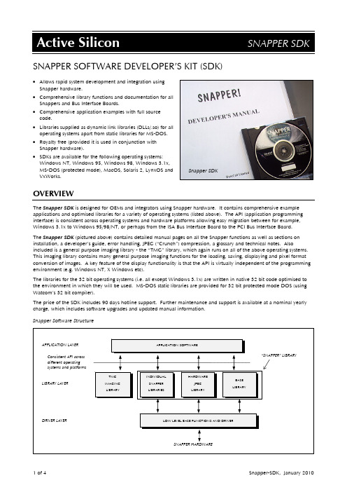
SNAPPER SOFTWARE DEVELOPER’S KIT (SDK)•Allows rapid system development and integration usingSnapper hardware.•Comprehensive library functions and documentation for allSnappers and Bus Interface Boards.•Comprehensive application examples with full sourcecode.•Libraries supplied as dynamic link libraries (DLLs/.so) for alloperating systems apart from static libraries for MS-DOS.•Royalty free (provided it is used in conjunction withSnapper hardware).•SDKs are available for the following operating systems:Windows NT, Windows 95, Windows 98, Windows 3.1x,MS-DOS (protected mode), MacOS, Solaris 2, LynxOS andSnapper SDKVxWorks.OVERVIEWThe Snapper SDK is designed for OEMs and integrators using Snapper hardware. It contains comprehensive example applications and optimised libraries for a variety of operating systems (listed above). The API (application programming interface) is consistent across operating systems and hardware platforms allowing easy migration between for example, Windows 3.1x to Windows 95/98/NT, or perhaps from the ISA Bus Interface Board to the PCI Bus Interface Board.The Snapper SDK (pictured above) contains detailed manual pages on all the Snapper functions as well as sections on installation, a developer’s guide, error handling, JPEG (“Crunch”) compression, a glossary and technical notes. Also included is a general purpose imaging library - the “TMG” library, which again runs on all of the above operating systems. This imaging library contains many general purpose imaging functions for the loading, saving, displaying and pixel format conversion of images. A key feature of the display functionality is that the API is virtually independent of the programming environment (e.g. Windows NT, X Windows etc).The libraries for the 32 bit operating systems (i.e. all except Windows 3.1x) are written in native 32 bit code optimised to the environment in which they will be used. MS-DOS static libraries are provided for 32 bit protected mode DOS (using Watcom’s 32 bit compiler).The price of the SDK includes 90 days hotline support. Further maintenance and support is available at a nominal yearly charge, which includes software upgrades and updated manual information.Snapper Software StructureSNAPPER SDK INFORMATIONSupported Operating Systems and Platforms:OS OS Level Platform CompilerWindows NT: v4.0 or above x86 Microsoft Visual C++ (v4.0 or above). Windows 95: - x86 Microsoft Visual C++ (v4.0 or above). Windows 98: - x86 Microsoft Visual C++ (v4.0 or above). Windows 3.1x: - x86 Microsoft Visual C++ (v1.0 , 1.5, 1.51),Microsoft Visual Basic (v3.0 or above). MS-DOS: - x86 Watcom C++ (v10.5 or above) usingWatcom’s 32 bit flat model and Flashtek’sX-32VM DOS extender.MacOS System 7.5 and above, orSystem 8 and aboveAny PCI Mac Metrowerks CodeWarrior Professional 3.Solaris 2: Solaris 2.6 or above. Sparc(SBus & PCI) SunSoft’s SPARCompiler C (v2.0 or above) and GNU C (v2.5 or above).LynxOS: LynxOS 2.5LynxOS Cetia Uni/RT 2.4 X86,PowerPC 603and aboveGCC v2VxWorks: Tornado 1.0.1 PowerPC 603and above.Tornado 1.0.1NOTE:1.The above compilers are fully supported and the example applications are all written with these compilers. Codegenerated on alternative compilers for the above operating systems will also work with the supplied libraries for that operating system.2.Solaris 2.3 is also available but does not include the latest library features and should NOT be used for new projects.SDK Contents:•Comprehensive application examples with full source code: Windows NT/95/98/3.1x are all written using the Microsoft MFC application framework.•Libraries for Windows NT/95/98/3.1x are provided as DLLs (dynamic link libraries). The libraries for Solaris 2 are provided as “.so” (shared object) libraries. Device drivers are provided for each operating system (capable of full DMA as appropriate) which provide the interface between the libraries and the hardware. All Snapper libraries are optimised for the operating system. In other words native 32 bit code is used for 32 bit operating systems.•TMG imaging library - A general purpose imaging library, which includes software JPEG compression and decompression - again optimised to the operating system. Example source code for custom TMG functions is also included.•ActiveX SDK for Windows NT/95/98 developers. The SnapperTool application is provided, not only as an example of an ActiveX program, but also as a simple image acquisition tool.•Comprehensive Developer’s Manual.•90 days telephone support and software upgrades.Support:Support is provided by telephone, fax, e-mail and web site. Yearly support contracts may be purchased which provide telephone support, access to the web-site/FTP site and typically several upgrades per year.TMG Imaging Library:The Snapper SDK is supplied with a general purpose image library referred to as the TMG library. This library provides general purpose imaging functions such as file loading, saving, pixel format conversion etc, as well as JPEG software compression and decompression and display functions. The display API is simple to use and virtually identical across alloperating systems. (Under MS-DOS, the Flash Graphics library from Flashtek is also required - Snapper part numberDOS-FG-LIB.) Other functions include chroma keying, colourmap/palette generation and LUT operations.32 Bit DOS Extenders:The X-32VM DOS extender is a pre-requisite when using the Watcom compiler (Snapper part number DOS-X32-LIB). This allows Flash Graphics compatibility and PCI DMA support.EXAMPLE APPLICATIONSThis example is a complete program that shows how an image is acquired from a Snapper module (Snapper-24 in this example), displayed, then saved as a TIFF file. (This code is written for MS-DOS, but it is identical for all other operating systems, apart from some additional TMG_display calls that may be required).#include <asl_inc.h>int main(ui16 argc, char** argv){Thandle hBase, hSnapper; /* handle to baseboard and Snapper */Thandle hSrcImage, hRGB24Image; /* handle to images */Thandle hDisplay; /* handle to display *//* Initialize the Bus Interface Board, Snapper and Display */hBase = ASL_get_ret(BASE_create(BASE_AUTO));hSnapper = BASE_get_parameter(hBase, BASE_MODULE_HANDLE);hSrcImage = TMG_image_create();hRGB24Image = TMG_image_create();hDisplay = TMG_display_init(hDisplay, TMG_800x600x24); /* 800 by 600, 24 bit *//* Initialize the Snapper in its default RGBX32 bit acquisition mode */SNP24_initialize(hSnapper, SNP24_CCIR_DEFAULT);SNP24_set_image(hSnapper, hSrcImage); /* set image parameters *//* Capture an image, display it and write it to a TIFF file */SNP24_capture(hSnapper, SNP24_START_AND_WAIT);SNP24_read_video_data(hSnapper, hSrcImage, TMG_RUN);TMG_display_image(hDisplay, hSrcImage, TMG_RUN);/* Convert from pixel format RGBX32 to RGB24 */TMG_image_convert(hSrcImage, hRGB24Image, TMG_RGB24, 0, TMG_RUN);TMG_image_set_outfilename(hRGB24Image, "rgb24.tif");TMG_image_write(hRGB24Image, TMG_NULL, TMG_TIFF, TMG_RUN);/* Free memory and exit */BASE_destroy(BASE_ALL_HANDLES);TMG_image_destroy(TMG_ALL_HANDLES);}ORDERING INFORMATIONPART NUMBER DESCRIPTIONSNP-SDK Snapper Software Development Kit.This includes a printed copy of the manual and a CD containing support forWindows 95/98/NT, ActiveX, MS-Dos, MacOS and Solaris 2.The CD contains on-line documentation, driver files, library executables (DLLs or SOs),all header files, as well as all the source code for the examples from the SNP-APPS-CDdetailed below.SNP-SDK-RT Snapper Software Development Kit for Real Time Operating Systems.This includes a printed copy of the manual and a CD containing support for LynxOSand VxWorks as well as Windows 95/98/NT, ActiveX, MS-Dos, MacOS and Solaris 2.The CD contains on-line documentation, driver files, library executables (DLLs or SOs),all header files, as well as all the source code for the examples from the SNP-APPS-CDdetailed below.SNP-SDK-MAN Snapper Software Development Kit printed manual only, as detailed above.SNP-SDK(-RT)-CD Snapper Software Development Kit CD only, as detailed above.SNP-SDK(-RT)-SUP 12 month support and upgrade contract for SDK.SNP-APPS-CD Snapper Application Examples. This consists of pre-compiled examples on a CD. DOS-FG-LIB Flashtek’s “Flash Graphics” library is required in addition to the SNP-SDK for imagingapplications under MS-DOS. This library is royalty free and works with the Watcomcompiler and the X-32VM DOS extender.DOS-X32-LIB Flashtek’s X-32VM 32 bit DOS extender. This is pre-requisite for use with the Watcomcompiler (it allows Flash Graphics and PCI DMA support).SNP-IG Snapper Installation Guide. This is included in the SDK manual, but is available as aseparate item free of charge.TMG-LIB-SW-LIC Software licence to use the TMG library (including its JPEG compression /decompression software and display software) without Snapper hardware. The use ofthe TMG library is free of charge as long as it is used in conjunction with Snapperhardware. If it is used independently (for example - software only JPEG decompressionand display) then a licence must be purchased.ORDERING NOTES•Further operating systems will be supported as PCI becomes available on other platforms - for example DEC Alpha workstations and PowerPC based systems.•Please contact Active Silicon for latest information on other Snappers, Bus Interface Boards, and supported operating systems.USAActive Silicon, Inc479 Jumpers Hole Road, Suite 301, Severna Park, MD 21146, USATel +1 410 696 7642Fax +1 410 696 7643**********************EuropeActive Silicon Limited Pinewood Mews, Bond Close, Iver Bucks, SL0 0NA, UKTel +44 (0) 1753 650600 Fax +44 (0) 1753 651661**********************All trademarks referred to in this datasheet are the property of their respective owners。
SNAPAV 产品维修指南说明书
page | 21.Read these instructions.2.Keep these instructions.3.Heed all warnings.4.Follow all instructions.5.Do not use this apparatus near water.6.Clean only with dry cloth.7.Do not block any ventilation openings. Install in accordance with the manufacturer’s instructions.8. Do not install near any heat sources such as radiators, heat registers, stoves, or other apparatus (including amplifiers) that produce heat.9. Do not defeat the safety purpose of the polarized or grounding-type plug. A polarized plug has two blades with one wider than the other. A grounding type plug has two blades and a third grounding prong. The wide bladed or the third prong are provided for your safety. If the provided plug does not fit into your outlet, consult an electrician for replacement of the obsolete outlet.10. Protect the power cord from being walked on or pinched particularly at plugs, convenience receptacles, and the point where they exit from the apparatus.11. Only use attachments/accessories specified by the manufacturer.12. Use only with the cart, stand, tripod, bracket, or table specified by the manufacturer, or sold with the apparatus. When a cart is used, use caution when moving the cart/apparatus combination to avoid injury from tip-over.13. Unplug this apparatus during lightning storms or when unused for long periods of time.14. Refer all servicing to qualified service personnel. Servicing is required when the apparatus has been damaged in any way, such as power-supply cord or plug is damaged, liquid has been spilled or objects have fallen into the apparatus, the apparatus has been exposed to rain or moisture, does not operate normally, or has been dropped.15. The equipment shall be used at maximum 35 degree C ambient temperature.16. To reduce the risk of electrical shock, do not open the equipment. For safety reasons it is only allow to the opened by qualified service personnel.17. WARNING: To reduce the risk of fire or electric shock, do not expose this apparatus to rain or moisture.Additionally, the apparatus shall not be exposed to dripping or splashing and no objects filled with liquids shall be placed on the apparatus.18. The MAINS plug is used as the disconnect device and shall remain readily operable.19. The product shall be used on open bench.20. No naked flame sources, such as lighted candles, should be placed on the apparatus.21. The apparatus should be connected to a mains socket outlet with a protective earthing connection. Support 866.838.5052page | 3 FEATURES1. POWERRed: Off/StandbyBlue: On/Operating2. RCA LINE LEVEL INPUTSLFE IN: Connects the left female RCA input to an LFE output connection on a receiver or pre-amp processor.L/R IN: Connects the left and right female RCA input to the left and right front output connections on a receiver or pre-amp processor.3. RCA LINE LEVEL OUTPUTSOUT: Connects additional amplifiers.4. 12V TRIGGER IN/OUT12V TRIGGER IN: Turns on the amp when a 12V signal is received from another 12V trigger device.12V TRIGGER OUT: Sends a 12V signal to another 12V trigger device.5. EQ SETTINGSEQ Preset A: +4dB (optimized for enclosures > 4 cu. ft.)EQ Preset B: +7dB (optimized for enclosures 1-4 cu. ft.)EQ Preset C: +10dB (optimized for enclosures < 1 cu. ft.)6. EQ MODEON: EQ SETTINGS are enabled, while CROSSOVER, PHASE and VOLUME also remain enabled.BYPASS: EQ SETTINGS are disabled, while CROSSOVER, PHASE and VOLUME remain enabled.7. POWER MODESTRIGGER: Amplifier turns on when 12V signal is detected and off when 12V signal is absent.AUTO: Auto sense enabled. Amplifier turns on when audio signal is detected. Unit enters standby mode if no signal is sensed after 15 minutes.ON: Always on. Amplifier does not turn off automatically. Unit turns on/off using the front panel power button.8. CROSSOVERAdjusts from 50 to 300 Hz.NOTE: When using the LFE input, set to LFE so the preamplifier or receiver can control the crossover frequency.9. PHASEAdjusts blending of the subwoofer with other speakers.10. VOLUMEAdjusts master volume to the desired listening level.11. SPEAKER OUTPUTSConnects the speaker wires to the binding posts.NOTE: Total impedance (SUB 1 + SUB 2) should not be less than 4Ω.12. VOLTAGE SELECTORSelects the appropriate input voltage setting: 100V or 230V.13. AC POWER INIEC power cord.© 2015 Episode®page | 4FEATURES (CONTINUED)14. FUSEAdditional fuse included for servicing.15. MASTER POWER SWITCHSwitch between on/off.SETUPAmplifier PositioningPlacing the amplifier can have a large impact on performance and longevity. Please take the following guidelines into consideration.• Ensure that the unit is in a well-ventilated area that provides adequate cooling.• A minimum of 5” should be allowed for optimum performance.Installation• Rack mount ears may be removed if the unit will not be installed in a rack.• Bottom feet on the amplifier chassis may be removed if necessary. Support 866.838.5052page | 5CONNECTCAUTION: All connections and switching must be done with the amplifier turned off. Connect the power cord last to ensure that the amplifier is off during all the connections and set up.RCA Line LevelUse high-quality RCA cables that feature low impedance with adequate shielding and high-quality connectors.Speaker OutputsUse 14-18 gauge stranded two-conductor speaker wire. Connect the appropriate conductor to each screw terminal, observing correct polarity.CAUTION: When two subwoofers are connected in parallel, the nominal impedance of each subwoofer should not be less than 8Ω.© 2015 Episode®page | 612V DC TriggerConnect the 12V trigger output of any other device with a 12V trigger cable to the input of the EA-AMP-SUB-1D-150 using a high-quality 3.5mm (1/8”) mono cable.If the receiver does not have a 12V trigger output, using a 12V power supply plugged into a switched outlet on the receiver provides the same functionality.(Tip) Support 866.838.5052page | 7FINE TUNEAfter making all connections and calibrating the speakers, fine tune the subwoofer as instructed below.NOTE: When using an AV receiver and the LFE input, set the subwoofer calibration level to the factory setting.1. Ensure that the subwoofer is plugged in.During initial setup, set the ‘POWER MODES’ switch to the ‘ON’ position. Once calibration is complete, switch to ‘AUTO’ to enable the automatic power-saving mode. For reference, the different modes are as follows:TRIGGER: Amplifier turns on when 12V signal is detected and off when 12V signal is absent.AUTO: Auto sense enabled. Amplifier turns on when audio signal is detected. Unit enters standby mode if no signal is sensed after 15 minutes.ON: Always on. Amplifier does not turn off automatically. Unit turns on/off using the front panel power button.2. If using one of the EQ presets, switch the ‘EQ MODE’ to the ‘ON’ position. Then select the desired setting.EQ PRESET A: +4dB (optimized for enclosures > 4 cu. ft.)EQ PRESET B: +7dB (optimized for enclosures 1 to 4 cu. ft.)EQ PRESET C: +10dB (optimized for enclosures < 1 cu. ft.)3. Set the controls to positions that will enable tuning for maximum performance.VOLUME set to 50%, or 12 o’clockCROSSOVER set to 175 Hz, or 12 o’clock – OR – set to ‘LFE’ if LFE input is usedPHASE set to 0º4. Play a movie scene or music track and set the system volume to an average level. Listen to the bass level fromthe preferred listening position. Adjust the ‘VOLUME’ control as desired.5. I f deeper bass is desired, adjust the ‘CROSSOVER’ control toward the lower frequencies. Experiment withdifferent frequency settings until finding one that sounds best.NOTE: When using the LFE input, set to LFE and make any crossover adjustments in the preamplifier or receiver crossover settings.6. Continue listening to music and movie sources using the settings chosen for volume and crossover.7. Experiment with the phase until finding the best setting. Depending on the subwoofer’s placement, the bassmay sound louder or deeper when the phase has been optimized. In some cases, adjusting phase will make no discernible difference.© 2015 Episode®SPECIFICATIONSContinuous Power Output80 watts RMS at 8 ohms150 watts RMS at 4 ohmsInput Sensitivity140 mV for full output (L/LFE only driven), 150 watts, with level control set to max Frequency Response30-200Hz (EQ MODE set to BYPASS)Distortion.10% THD+N 1W/2W 100 HzAuto On Sensitivity 4 mVExternal Trigger Voltage 2.0 V - 20 VDimensions16.9” W (19” including rack mounts)1.75" H (2.1" including feet)8.1" D (front switch to rear chassis)8.9" D (front switch rear speaker connector)Weight 5.9 lbsCertification TUV Listed and tested under UL/EN60065 for US and Canada TROUBLESHOOTINGEpisode amplifiers are designed to function trouble-free. Most problems that occur are due to simple issues. I f having trouble, check the list of simple fixes below. If the problem persists, contact Episode technical support at 866-838-5052.No audio output • Power cable to the amplifier is incorrectly connected or plugged into an outlet that does not have power. Check connections and verify power at the outlet.• Audio cable to the source component is not connected properly, connection to output or the cable is defective. Check connections or replace cable with one that has been verified as good.• Amplifier is in standby mode and needs to be turned on (blue LED).• Check the connections of the speaker wire at both the speaker and amplifier.• The level adjustment is turned down. Slowly turn the dial to the right to raise the volume.Hum or buzzing sound is heard • Check RCA input cables by removing them one at a time (powering down the amplifier before disconnecting) and verify connections.Amplifier will not turn on • Ensure the amplifier is plugged into a live outlet.• Ensure the power switch on the front panel is on (blue LED).• Fuse is blown. Replace with T3.15AL/250V fuse type.• The power mode may be set to the wrong mode for the system’s configuration or setup.WARRANTY2-Year Limited WarrantyEpisode® Amplifiers have a 2-Year Limited Warranty. This warranty includes parts and labor repairs on all components found to be defective in material or workmanship under normal conditions of use. This warranty shall not apply to products which have been abused, modified or disassembled. Products to be repaired under this warranty must be returned to the SnapAV or a designated service center with prior notification and an assigned Return Authorization (RA) number.CONTACTING TECHNICAL SUPPORTAs a thank you for purchasing Episode® Electronics products, direct technical support services are available via phone or e-mail. We encourage you to use this resource for any questions or concerns about our products. Visit our website for more support documentation.(866) 838-5052**********************© 2015 Episode®Rev: 15002-1510。
Snap-on ECO Xtreme 安装说明书
INSTALLATION OVERVIEW:______________________________________________The Installation Procedure listed is for the Snap-on ECO Xtreme™ (EEAC318A). The unit is shipped asa fully assembled unit, with the exception for the items listed in the Parts & Accessories.PLEASE READ THESE INSTRUCTIONS COMPLETELY BEFORE SETTING UP UNITPARTS & ACCESSORIES:________________________________________________PART NUMBER DESCRIPTION QTY1-15080 Adapter, Low Side 11-27180 Adapter, Vehicle, High Side 11-27280 Adapter, Vehicle, Low Side 11-05585A Bottle, Disposable 8oz. 15-1145 Plastic tie wrap 1Certificate 1 8-1163 Equipment8-1263 Technician Certificate 1EAA0275L05A Recovery Tank Assembly (R-134a) 1EAH0001C01A Red Hose 1Hose 1EAH0001C02A BlueTEEAC318A0 Installation Instructions 1Manual 1 ZEEAC318A User’sREQUIRED TOOLS:_____________________________________________________•Safety Goggles•R-134a Virgin Tank (Supplied by Customer)•GlovesPARTS & ACCESSORIES SETUP__________________________________________1. Remove the Blue and Red Hoses from the box, along with the plastic-tie-wrap. Remember toOIL the seals on each end of the hoses.2. Connect the high (red) and low (blue) couplers to their respective hoses. Rotate coupler knobsfully CCW (closed).3. Route both hoses in-between the master filter bracket and the hose that connects to the filter.4. Attach other end of the (red) hose to upper, red labeled (high side) port on the back panel of theEco Xtreme™ unit.5. Attach other end of the blue hose to lower, blue labeled (low side) port on the back panel of theEco Xtreme™ unit.6. The plastic-tie wrap will be used later, to secure the hoses to the master filter bracket. (Page 4,line 12).7. Install plastic oil bottle (1-05585A) to the white cap mounted in the front of the unit.8. Remove the User's Manual, MAC Form/Certification, Product Registration Form, and WarrantyRegistration from the box. Hand these items to the Owner or Manager.9. Remove Recovery Tank (EAA0275L05A) from its box. Remove cardboard wrap from RecoveryTank and set on floor.PREPARING RECOVERY TANK:__________________________________________1. Referring to FIGURE 1, open the BLUE valve onRecovery Tank to release ALL COMPRESSED AIR. 2. Gently set the Recovery Tank on the scale. 3. Place the strap around the recovery tank.4. Position the Temperature Probe between the tank andthe strap. 5. Install the supplied tank adapter 1-15080 on the Low(blue) side of the recovery tank. 6. Attach the blue vehicle hose w/adapter to the Low sideof the tank. 7. Plug AC Cord to a proper 115VAC outlet. And turn-onthe unit by the rear panel switch.NOTE: In the unlikely event, the LCD screen isunreadable upon power up, adjust LCD contrast. Refer to the users manual for contrast adjustment.8. Press the Down arrow, Arrow on display will be pointing to “VACUUM”.a. Press <ENTER>.b. Press the Down arrow until desired amount of vacuum time is displayed.c. Turn the front panel low panel valve to VACUUM.d. Press Start button, vacuum pump should turn ON in about 5 seconds. 9. The low side gauge shows vacuum increasing.10. Monitor low side gauge until a minimum of 25 inches has been reached.11. Once completed, close the Recovery Tank valve (BLUE). Close the R-134a Coupler. 12. Press EXIT button. The pump will shut-off. 13. Remove the blue service hose from the tank.NOTE: Remove the R-134a tank adapter, (1-15080) and place in the storage tray. 14. the yellow hose to the tank purge port. See figure to the right. 15. Identify the blue hose leading from the bottom of the unit.16. If you are going to continue with Gravity refrigerant transfer(found on page 4), leave the red hose disconnected.Otherwise identify the red hose leading from the bottom ofthe unit. Connect hose with the anti-blowback valve to the red (vapor) valve.17. Open both red and blue valves on tank unless continuing with Gravity Transfer method.18. If you are going to continue with Gravity refrigerant transfer, do not attach plastic –tie. Using theplastic-tie wrap (5-1145) route the tie through the hole in the bracket, wrap around the hoses and tie.Refer to the users manual for pre-charging tanks. Refer to next page for first time fast charge.INSTALLATION COMPLETEFIGURE 1 RECOVERY TANKPRE-CHARGING RECOVERY TANKS USING GRAVITY METHOD:NOTE: THIS PROCEDURE IS USED TO SETUP THE UNIT FOR CHARGING. RECOVERY TANKSHOULD HAVE AT LEAST A 25” VACUUM. THIS PROCEDURE IS DONE WHEN RECOVERY TANK IS ON THE SCALE1. Plug unit in and turn on, go into Charge screen tomonitor tank weight.2. Be sure Recovery Tank valves (B) are closed andtank is in vacuum on scale. Refer to FIGURE 2. 3. Disconnect the Red hose from the Recovery Tank. 4. Disconnect and Re-Oil both the seals on blue hose(C). Connect the one side of the blue Hose w/ adapter (1-15080) to the Virgin Tank (A). 5. Connect the other end of the blue Hose to the RedValve on the Recovery Tank (B). 6. Open the Red Valve on the Recovery Tank. 7. Raise the Virgin Tank to a higher level than theRecovery Tank. Invert the Virgin Tank (A) and open valve. 8. Gravity and vacuum will transfer the liquid refrigerantto the Recovery Tank faster than recovering it.NOTE: DO NOT OVER CHARGE TANK. THESAFE AMOUNT TO CHARGE IS AROUND 15 LBS. 9. After the desired amount of refrigerant has beentransferred, close valves on Virgin Tank first, pause to allow refrigerant to flow into tank, then close recovery tank valve. Set Virgin Tank on ground upright. 10. Disconnect blue hose, and adapter from both Tanks. 11. Re-Oil seals on anti-blow back valve on the RedHose from unit and connect to Recovery Tank. Open both Recovery Tank valves.12. Re-Oil seals on red and blue hoses. To connect thehoses, route both in-between the master filter bracket and the hose that connects to the filter. Connect the open end of the Blue hose to the Low side bulkhead fitting and Red Hose to the high side bulkhead fitting. Using the plastic-tie wrap route the tie through the hole in the bracket, wrap around the hoses and tie. 13. Unit is ready to recover and charge refrigerant.FIGURE 2 CHARGING TANKREMEMBER TO OIL O-RINGS AND SEALS WHEN ATTACHING HOSES OR FITTINGS。
美国尼特特尔摄影公司的美国产品说明书
2. Closing. (fig. 3)
Press with the left hand ,
0o 0------------------------------
-----------------00
o
Nettel [amerawerk G.:m. b. H., Sontheim a. N. \
111111111111111111111111111111111111111111111111 1111111111:lllllllllllllllllllilllllllllllllllllllllllllllll111111111111111111111111111111111111111111111111111111
or by some other means, (Heyde's ms.ter)
that for the object in question an exposure
of 1/120 second is necessary, in order to
obtain a thoroughly good negative, the
~- -~i-5-EJ.<l:H·t&- 0 ]3e n-uflti!.,th~ E. og0-~E t O U8::.~-"'B'i-±li3r?:'-''~'Ii''~),Ir---;'''''''~
Snap-on Equipment RFV 2000 工具箱配件说明书
WHEEL BALANCER
Parts Manual
1
TEEWB546B
All information contained or disclosed in this document is considered confidential and proprietary by Snap-on Equipment. All manufacturing, use, reproduction, and sales rights are reserved
11
3-03708A MONITOR-LCD 17W
13
1-1115
BOLT-HEX 5/16-18X3 UNC 2A TAP
16
EAA0247G21A
CALIPER-RIM WIDTH
17
EAA0307G54A
ACCY KIT-PWR CLAMP
18
EAA0369J08A
BALANCER ASSY -BFH 2000
29
EAL0343J76A LABEL-ELECTRICAL/SERIAL
30
EAL0349G87A LABEL-WHEEL #1
31
EAL0349G88A LABEL-WHEEL #2
32
EAL0349G89A LABEL-WHEEL #3
33
EAL0349G90A LABEL-WHEEL #4
PART NO EAS2116G12A 1-07824A 1-10041 1-11233 1-11744A 1-11961A 1-1248 1-13606A 1-14661A 1-14761A 1-16161A 1-16309 1-16509A1 1-17559A 1-17659a 1-17709 1-18359A 1-18523A1 1-03725A 1-20423 1-20504A 1-2676 1-3724 1-46809 1-51910A 1-9841 2-23201 2-28301A 2-48066A 2-732 3-05009A 3-60826AF1 6-08722A 6-08822A 6-09122A 6-09922A 6-10022A 8-7216 EAA0338G83B EAA0363G57A EAA0346J82A EAA0358G03A EAA0358G04A