安川伺服驱动器使用说明书
安川伺服驱动器PG-X2编码器反馈选件卡说明书

1. Part Number: PG-X2.2. Applicability: F7, G7, GPD515/G5, G5HHP.3. Introduction: The PG-X2 encoder feedback option card (Figure 1) is mounted on the drive’s Control Board and performs speed feedback using the pulse generator (PG) on the motor to correct speed fluctuation caused by motor slip. Motor rotation direction is detected by phase A and phase B PG pulse inputs. The terms encoder, PG (pulse generator), and pulse train are used interchangeably in this guide. The card can be used for flux vector control or V/Hz with PG feedback control.4. Receiving: All equipment is tested against defect at the factory. Report any damages or shortages evident when the equipment is received to the commercial carrier who transported the equipment.5. Cautions:a. Hazardous voltage can cause severe injury or death. Lock all power sources feeding the drive in the “OFF” position.b. This option card uses CMOS IC chips. Use proper electrostatic discharge (ESD) protective procedures whenhandling the card to prevent I.C. damage or erratic drive operation.c. If other option cards are to be installed at the Option C (2CN) or Option D (3CN) positions (See Figure 2), theirinstallation and wiring should be completed before installation of this option.d. Before installing this option, a technically qualified individual, who is familiar with this type of equipment and thehazards involved, should read this entire installation guide.Figure 1. PG-X2 Encoder Feedback CardFigure 2. PG-X2 Option Card installationMounting HoleConnector, Rear Side of Board to Control Bd., 4CNTerminal Block TA2Terminal Block TA1Variable Resistor,Adjusts +12V PG PowerVariable Resistor,Adjusts +5V PG PowerTerminal TA3 Connect ShieldHere2 Mounting HolesGround Lead Wire- Connects to Grounding Terminal on Control BoardFigure 3. Mounting Spacer 6. Precautions and Preliminary Installation:a. Remove contents from package. Verify that a mounting spacer(P/N 5RNT41028-9) is included with the card. See Figure 3. b. Disconnect all electrical power to the drive. c. Remove the drive’s front cover.d. Check that the “CHARGE” indicator lamp inside the drive is off.e. Use a voltmeter to verify voltage at incoming power terminals(L1, L2, L3) has been disconnected.f. Insert the spacer into the mounting hole in the base of the drive,just above the top edge of the control board. See Figure 2. g. Note: When re-installing the cover, please take care not to pinchany of the encoder wires.h. Important: GPD 515/G5 models 20P2 to 22P2 and 40P2 to 41P5 have two closely spaced mounting holes. Insertthe spacer into the hole closest to the control board’s connector 4CN. If inserted in the wrong hole, the spacer WILL NOT properly align with the PG-W2’s mounting hole.7. PG-X2 Installation: See Figure 2.a. Position the bottom edge of the option card into the mounting bracket on the control board’s terminal block. Align twomounting holes in the card with pins on the bracket.b. Then angle the top edge of the card into place, carefully aligning connector 4CN on the back of the card withconnector 4CN on the control board. Gently press the card into place until 4CN and the spacer click into place.8. Wiring: Refer to Figure 4 and Tables 1 & 2. Make wire connections between the PG-X2 card and encoder as well as any external monitoring circuits. Observe the following:a. The need for the marker Z (C) channel depends on the installed custom (CASE) software. Standard software doesnot use the marker pulse.b. Keep the PG-X2 (i.e. control circuit) wiring separate from main circuit input/output wiring. A separate metallicgrounded conduit with ONLY the PG wiring running through it is preferred.c. To prevent erroneous operation caused by noise interference, use shielded cable for control signal wiring, and limitthe distance to 50m (165 feet) or less.d. Recommended cable is twisted pair, 22AWG, with overall shield, such as Belden 9504. Refer to “ElectricalInstallation” in the drive technical manual for further information on use of shielded cable. The shielded sheath connection points on the PG-X2 card are terminal TA3.e. Strip back insulation for a distance of 0.22 in. on wire leads connected to the PG-X2 terminals.f. Connect the option card ground wire (E) to the drive’s ground terminal TB3 (12 for G5).9. Adjustment: The+12VDC and +5VDC outputs of the PG-X2 card are factory calibrated. No adjustment should be necessary.10. Cover: Reinstall and secure drive’s front cover.11. Programming: Table 3 lists all drive parameters related to encoder feedback. Ensure that all of these parameters are programmed to meet the requirements of the application.12. Start-up: Refer to Section 2 in the drive’s technical manual for testing and start-up information.13. IG Storage: Place this instruction guide with the drive’s technical manual.Table 1. Terminal FunctionsTerminal Block TerminalNumberFunction1 +12VDCPower supply for Pulse Generator (PG).Important: Use either +12V or +5V, but never both at the same time.2 0V +12VDC, 200mA max3 +5VDC +5VDC, 200mA max4 +5 -A Pulse6 +7 -B Pulse8 +9 -Z Pulse*TA110 0V CommonTerminalPG Signal Inputs RS-422 Level Input1 +2 -A Pulse3 +4 -B Pulse5 +6 - Z Pulse*TA27 IG5 Isolated Common Terminal Pulse Monitor Output RS-422 Level OutputTA3 Shield Drain for Encoder Wiring * Not required for standard software. May be required for custom software.Table 2. Terminal and Wire SpecificationsTerminal Symbol TerminalScrewClamping TorqueLb-in (N-m)Wire RangeAWG (mm 2)TA1, TA2 M21.8 to2.2(0.22 to 0.25)26 to 16(Stranded: 0.14 to 1)(Solid: 0.14 to 1.5)Notes:(1) Power Supply for PG (from PG-X2)TA1 1-2: +12VDC, 200mA max.Ta1 3-2: +5VDC, 200mA maxDo Not Use Both Supplies at theSame Time.(2) H20 Dynapar Encoder Connections ShownFigure 4. PG-X2 Interconnection Diagram14. Application: If the encoder’s power requirement is greater than 200mA, provide a separate power supply source as shown in Figure 5. If the momentary power loss ride thru function of the drive is to be used, include a backup capacitor in the PG power wiring or take other necessary precautions.Figure 5. Using Separate PG Power Supply15. Maximum Input Frequency: The maximum input frequency of the PG-W2 card is 300kHz. To find the output frequency of the encoder (PG) in Hertz, use the following formula. Please make sure a 20% safety margin is built-in.f PG (Hz) = Maximum Motor Speed (RPM) x Encoder PPR (Pulses/Rev)60Figure 6. Encoder (PG) Signals – Forward Direction16. Signal type / level requirements: The PG-X2 card requires a “quadrature line driver with compliments” signal type from the encoder (pulse generator). As shown in Figure 6, line driver signals include both a primary signal (Signal A+) and it’s compliment (Signal A-). The compliment is the inverse of the primary signal. This scheme is used to improve the noise immunity of the system. The encoder output signal voltage should be between +5VDC and +12VDC. An “open collector” signal type WILL NOT work with the PG-X2 card.A quadrature signal is one that lags the primary signal by 90 electrical degrees (1/2 of a pulse). The purpose of this is so that the drive can detect the direction of the encoder rotation. As shown in Figure 6, for “forward” rotation of the encoder, signal A+will lead signal B+ by 90o.If any one of the four signals is missing, the drive cannot accurately measure the encoder rotation speed or direction.17. Viewing Signals With An Oscilloscope: The PG-X2 option card has test points that can be used to connect anoscilloscope. Test points PA, PB, and PZ are after the compliment is subtracted out and the signals are buffered through the opto-isolators. See Figure 4. The voltage level on all test points varies between 0 and +5VDC (TTL).Caution: Always use an un-grounded oscilloscope so no noise is introduced into the common.Table 3. PG-X2 Test PointsTest Point DescriptionGNDAlthough labeled GND, it is NOT earth ground. This test point should only be used in conjunctionwith test points PA, PB, and PZ.PA Channel A (Terminals 4 & 5) PB Channel B (Terminals 6 & 7) PZ Channel Z (Terminals 8 & 8)Note: All signals shown are in relation to power supply common, Terminal 2 of the PG-X2.Table 3. GPD 515/G5, F7, and G7 Encoder Feedback Parameter List Control Method (2)D i g i t a l O p e r a t o rF u n c t i o nG r o u pD i g i t a l O p e r a t o r D i s p l a yP a r a m e t e r N u m b e rP a r a m e t e r N a m eS e t t i n g R a n g eF a c t o r y S e t t i n gC h a n g eD u r i n g O p e r a t i o n (1)D a t a S e l e c t i o nV /f w / P G F e e d b a c k F l u x V e c t o r PG Pulse/Rev F1-01 PG Constant 0 to 60000 1024 X O OPG Fdbk LossSel F1-02Operation at Open PG Circuit 0 to 31XOO PG OverspeedSel F1-03 Operation Selection at Overspeed 0 to 3 1 XO O PG DeviationSel F1-04 Operation Selection at Deviation0 to 3 3 X0: Ramp to Stop 1: Coast to Stop 2: Fast-Stop 3: Alarm OnlyO OPG RotationSel F1-05 PG Rotation0,1 0 X 0: Fwd = CCW1: Fwd = CW O OPG Ramp PI/ISel F1-07 IntegralControl during Accel/Decel 0,1 0 X 0: Disabled 1: EnableO XPG OverspeedLevel F1-08 Overspeed Detection Level 0 to 120% 115% XO OPG OverspeedTime F1-09 Overspeed Detection Delay Time 0 to 2.0s1.0s XO O PG DeviationLevelF1-10 Speed Deviation Detection Level 0 to 50% 10% XO O PG DeviationTime F1-11 Speed Deviation Detection Delay Time 0 to 10s 0.5s XO O PG# Gear Teeth 1 F1-12 Number of Gear Teeth 1 0 to 1000 0 X O X PG# Gear Teeth 2 F1-13 Number of Gear Teeth 2 0 to 1000 0 X O X PGO DetectTime F1-14 PGO DetectionTime 0 to 10s 2s XOOPGOption SetupSpeed Detection Filter SelectionF1-15Speed Detection Filter Selection0, 11X0: No Average 1: 2 Scan MovingAverageO OTable 3. GPD 515/G5, F7, and G7 Encoder Feedback Parameter List Control Method (2)D i g i t a l O p e r a t o rF u n c t i o nG r o u pD i g i t a l O p e r a t o r D i s p l a yP a r a m e t e r N u m b e rP a r a m e t e r N a m eS e t t i n g R a n g eF a c t o r y S e t t i n gC h a n g eD u r i n g O p e r a t i o n (1)D a t a S e l e c t i o nV /f w / P G F e e d b a c kF l u x V e c t o rASR P Gain 1 C5-01ASR Proportional Gain 1 0 to 300.00 0.00 O O OASR I Time 1 C5-02 ASR Integral Time 1 0 to 10.000s 0.00s O O O ASR P Time 2 C5-03 ASR Proportional Gain 2 0 to 300.00 0.00 O O O ASR I Time 2 C5-04 ASR Integral Time 2 0 to 10.000s 0.00s OO O ASR Limit C5-05 ASR Limit 0.0 to 20% 0.0% X O X ASR DelayTime C5-06 ASR Primary Delay Time 0.000 to 0.500s 0.000s X X O ASR Gain SWFreq C5-07 ASR Switching Frequency 0.0 to 400.00Hz 0.0Hz X X O ASRTuningASR IntegralLimitC5-08ASR IntegralLimit0 to 400%400% XX O(1) O = Yes, X = No.(2) O = Available, X = Hidden. The PG-X2 is not applicable for A1-02 = 0 (V/f Control) or 2 (Open Loop Vector).。
sanka伺服驱动器说明书

sanka伺服驱动器说明书安川伺服驱动器SGDV-2R8A01A报警代码7RB是什么回事安川伺服驱动器上电后运行10分钟后报警A32,断电又好了,10分钟后又是A32,850w的紧急安川伺服驱动器SGDV-2R8A01A报警410是什么原因?安川伺服驱动器A81报警怎么办?编码器是**值的,A81编码器备份报警安川伺服电机SGDM-01ADAA10报警是什么原因安川伺服驱动器_56。
“-08人。
人_报警A10维修安川SGDM-20ADA伺服驱动器机床运行时老是AC9报警就死机了重新上电又好再做又同样.请教,安川SGDM-20ADA伺服驱动器,AC9报警是什么内容?无锡安川SGDM-1**DA伺服驱动器报警说明与维修安川伺服驱动器显示AC9是什么意思?安川伺服驱动器报警维修、a.30故障代码维修SGDM-50ADA安川伺服驱动器维修报警A40质高**安川SGDH伺服报警A10怎么解决啊安川伺服驱动器偶尔报警C90的故障处理编码器沈阳数控CAK6150P,伺服是安川SERVOPACK.SGDB-0**DG伺服器报警,你要看伺服器上边的报警代码,只看数控上显示的代码一般无法确定伺服系统的报警原因的,一般伺服系统是过热或者过载等原因安川伺服驱动器报警A10维修SGDM-08ADA安川伺服驱动器先显示A91后显示AC9,是什么故障呢。
安川SGDB-3ZDD伺服驱动维修,A10报警,A81报警,A40报警安川伺服驱动器SGDM上电报A.F6故障安川伺服驱动器报警AEA0,是什么问题?能修吗?是那个元件坏了?安川伺服SGDS-02A12A报警AEA0故障,怎么维修?安川伺服驱动器参数表和功能表安川伺服驱动器出现A.71报警怎么解决。
安川(YASKAWA)伺服维修:可修复安川伺服驱动器报警:A.00,A.02,A.O4,A.10,A.30,A.31,A.40,A.51,A.71,A.72,A.80,A.81,A.82,A.83,A.84,A.85,A.A1,A.B1,A.C1,A.C2,A.C3,A.C4,A.C9,A.F1,A.F3,A.99等故障。
SGD7S~120A00A驱动器说明书手册
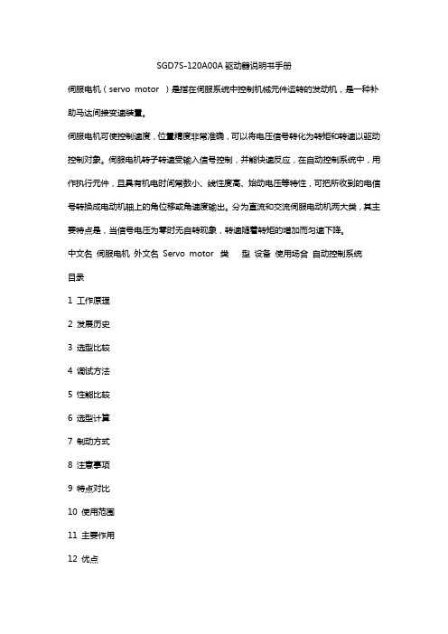
SGD7S-120A00A驱动器说明书手册伺服电机(servo motor )是指在伺服系统中控制机械元件运转的发动机,是一种补助马达间接变速装置。
伺服电机可使控制速度,位置精度非常准确,可以将电压信号转化为转矩和转速以驱动控制对象。
伺服电机转子转速受输入信号控制,并能快速反应,在自动控制系统中,用作执行元件,且具有机电时间常数小、线性度高、始动电压等特性,可把所收到的电信号转换成电动机轴上的角位移或角速度输出。
分为直流和交流伺服电动机两大类,其主要特点是,当信号电压为零时无自转现象,转速随着转矩的增加而匀速下降。
中文名伺服电机外文名Servo motor 类型设备使用场合自动控制系统目录1 工作原理2 发展历史3 选型比较4 调试方法5 性能比较6 选型计算7 制动方式8 注意事项9 特点对比10 使用范围11 主要作用12 优点工作原理编辑1、伺服系统(servo mechanism)是使物体的位置、方位、伺服电机状态等输出被控量能够跟随输入目标(或给定值)的任意变化的自动控制系统。
伺服主要靠脉冲来定位,基本上可以这样理解,伺服电机接收到1个脉冲,就会旋转1个脉冲对应的角度,从而实现位移,因为,伺服电机本身具备发出脉冲的功能,所以伺服电机每旋转一个角度,都会发出对应数量的脉冲,这样,和伺服电机接受的脉冲形成了呼应,或者叫闭环,如此一来,系统就会知道发了多少脉冲给伺服电机,同时又收了多少脉冲回来,这样,就能够很精确的控制电机的转动,从而实现精确的定位,可以达到0.001 mm。
直流伺服电机分为有刷和无刷电机。
有刷电机成本低,结构简单,启动转矩大,调速范围宽,控制容易,需要维护,但维护不方便(换碳刷),产生电磁干扰,对环境有要求。
因此它可以用于对成本敏感的普通工业和民用场合。
无刷电机体积小,重量轻,出力大,响应快,速度高,惯量小,转动平滑,力矩稳定。
控制复杂,容易实现智能化,其电子换相方式灵活,可以方波换相或正弦波换相。
安川伺服参数设定

安川伺服参数设定一、伺服参数设定的目的和重要性伺服参数设定的目的是通过调整伺服驱动器的参数,使驱动器能够更好地与传动机构和机械装置配合,确保系统的动态响应和控制精度,提高工作效率和精度。
伺服参数设定是伺服系统调试和性能优化的关键步骤,对于确保系统的正常运行和提高生产效率具有重要意义。
二、伺服参数设定的方法和步骤伺服参数设定的方法和步骤主要包括以下几个方面:1.前期工作准备在开始伺服参数设定之前,需要清楚地了解伺服系统的工作原理和性能要求。
同时,需要对伺服驱动器和伺服电机进行正确的接线和配置,确保驱动器和电机之间的通信和控制有效。
2.系统标定系统标定是指通过对伺服系统进行一系列测试和数据采集,获取系统的动态响应特性和传动机构的静态特性。
常见的系统标定参数包括位置环、速度环、加速环等。
3.参数优化通过对系统标定数据的分析和处理,可以优化伺服系统的参数,使其能够更好地适应实际应用需求。
参数优化主要包括位置环增益、速度环增益、加速环增益等。
4.参数设定在参数优化的基础上,根据具体应用需要,对伺服驱动器进行参数设定。
参数设定主要包括电机参数(如极数、电机额定转矩、电机最大转速等)、速度环参数(如速度环增益、速度环带宽等)、位置环参数(如位置环增益、位置环带宽等)。
5.测试和调试在完成伺服参数设定之后,需要对系统进行全面的测试和调试,以确保系统的性能和稳定性。
测试和调试主要包括对系统的速度响应、位置跟踪精度、扭矩输出等方面进行检验。
三、伺服参数设定的注意事项在进行伺服参数设定的过程中,需要注意以下几个方面:1.合理选取参考值在设定伺服参数时,需要根据实际应用需求合理选择参考值,确保系统能够达到预期性能。
参考值过小或过大都可能导致系统出现不稳定现象。
2.学习型自整定功能的应用安川伺服驱动器通常具有学习型自整定功能,可以通过学习系统的特性自动调整参数。
在使用学习型自整定功能时,需要确保系统运行在典型的工作状态下,避免因为特殊状态造成参数的不准确或过于保守。
安川伺服调试
FG
外壳接地
编码器线
注意:
动力线
电机端 C D H K J
驱动器端 1、 编 码 器 线 需 带 电机端
5
屏蔽双绞电缆 A
6
线,外屏蔽连端 B
2
需连接可靠; C
1
2、 动 力 线 电 机 端 D
端子外壳
D 端子线,请切 E
记连接接驱动 F
器外壳接地;
驱动器端 U V W 外壳接地 接刹车电 源端
安川伺服调试
FG
外壳接地
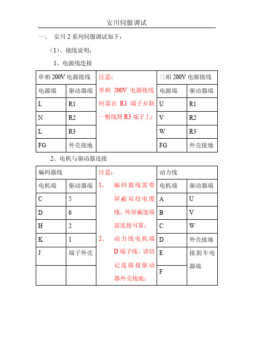
安川伺服调试
2、电机与驱动器连接
编码器线 电机端
小惯量 中惯量
4
1
注意:
动力线
驱动器 1、 端 5
编码器线需 带屏蔽双绞 电缆线,外 屏蔽与两端 端子外壳需 连接可靠;
电机端
小惯量
4
中惯量
A
驱动 器端 U
5
2
3
Байду номын сангаас
9
6
4
1 号端子 高而与
10
端子外
壳接地
6
2、
2
1 端子外
动力线电机 3
端 D 端子
线,请切记 2
连接接驱动
器外壳接 1
地;
5
壳
6
B
V
C
W
外壳接
D
地
E
接刹车 电源端
F
(2)参数设置
基本参数 增益参数
Pn000 Pn170 需将第 0 位设为 0
Pn200 Pn103 5 系列增益参数设置调试,需用伺服调试软件进行
Pn20E Pn100 整定,详细伺服软件调试请看下面附件说明;
安川伺服驱动器参数表和功能表精选文档

安川伺服驱动器参数表和功能表精选文档 TTMS system office room 【TTMS16H-TTMS2A-TTMS8Q8-安川伺服驱动器参数表安川伺服驱动器和凯恩帝数控系统相配时,只需设定以下参数(见参数表);其余参数,一般情况下,不用修改。
安川伺服驱动器和凯恩帝数控系统相配时,只需设定以下参数(见参数表);其余参数,一般情况下,不用修改。
Pn000 功能选择 (设定值) 第0位:设定电机旋转方向;设“1”改变电机旋转反向。
第1位:设定控制方式为:“1”位置控制方式。
Pn200 指令脉冲输入方式功能选择 (设定值)? “1”正反双路脉冲指令(正逻辑电平)(设定从控制器送给驱动器的指令脉冲的类型)Pn202 电子齿轮比(分子)Pn203 电子齿轮比(分母)根据不同螺距的丝杆与带轮比计算确定,计算方法如下:Pn202/Pn203=编码器条纹数(32768)X4 / 丝杠螺距×带轮比×1000参数设置范围: 1/100≤分子/分母≤100注:1. KND 系统内的电子齿轮比需设置为:CMR/CMD=1:1 (确保的分辨率);2. 如果是数控车床,X 轴用直径编程,则以上计算公式中,分母还应乘以2,即:丝杠螺距×带轮比×1000×2。
Pn50A 功能选择 (设定值) 1-使用/S-ON 信号(伺服启动信号)。
4-伺服驱动器上,“正向超程功能无效”。
Pn50B 功能选择 (设定值) 1-伺服驱动器上,“负向超程功能无效”。
Pn50E 功能选择 (设定值)? 配KND 系统时,设置为“0000”,详细见安川手册Pn50F 功能选择 (设定值)?3-伺服驱动器上,CN1 插头的27 和28 脚用作控制刹车用的24V 中间继电器的控制信号/BK。
(注:当电机带刹车时需设置)Pn506 伺服关时,在电机停止情况下,刹车延时时间根据具体要求设定注:设定单位以“10ms”为单位。
SGD7S120A00A驱动器说明书手册分解
SGD7S-120A00A驱动器说明书手册伺服电机(servo motor )是指在伺服系统中控制机械元件运转的发动机,是一种补助马达间接变速装置。
伺服电机可使控制速度,位置精度非常准确,可以将电压信号转化为转矩和转速以驱动控制对象。
伺服电机转子转速受输入信号控制,并能快速反应,在自动控制系统中,用作执行元件,且具有机电时间常数小、线性度高、始动电压等特性,可把所收到的电信号转换成电动机轴上的角位移或角速度输出。
分为直流和交流伺服电动机两大类,其主要特点是,当信号电压为零时无自转现象,转速随着转矩的增加而匀速下降。
中文名伺服电机外文名Servo motor 类型设备使用场合自动控制系统目录1 工作原理2 发展历史3 选型比较4 调试方法5 性能比较6 选型计算7 制动方式8 注意事项9 特点对比10 使用范围11 主要作用12 优点工作原理编辑1、伺服系统(servo mechanism)是使物体的位置、方位、伺服电机状态等输出被控量能够跟随输入目标(或给定值)的任意变化的自动控制系统。
伺服主要靠脉冲来定位,基本上可以这样理解,伺服电机接收到1个脉冲,就会旋转1个脉冲对应的角度,从而实现位移,因为,伺服电机本身具备发出脉冲的功能,所以伺服电机每旋转一个角度,都会发出对应数量的脉冲,这样,和伺服电机接受的脉冲形成了呼应,或者叫闭环,如此一来,系统就会知道发了多少脉冲给伺服电机,同时又收了多少脉冲回来,这样,就能够很精确的控制电机的转动,从而实现精确的定位,可以达到0.001 mm。
直流伺服电机分为有刷和无刷电机。
有刷电机成本低,结构简单,启动转矩大,调速范围宽,控制容易,需要维护,但维护不方便(换碳刷),产生电磁干扰,对环境有要求。
因此它可以用于对成本敏感的普通工业和民用场合。
无刷电机体积小,重量轻,出力大,响应快,速度高,惯量小,转动平滑,力矩稳定。
控制复杂,容易实现智能化,其电子换相方式灵活,可以方波换相或正弦波换相。
安川5系列耐环境型伺服接线及基本参数设置说明
一、 安川5系列伺服调试如下:(1)接线说明: 1、电源线连接 单相200V 电源接线三相200V 电源接线电源端 驱动器端 电源端 驱动器端L L1 R L1N L2 S L2L3 T L3FG 外壳接地 FG 外壳接地 L L1C R L1CN L2C注意:1、SGMJV 、SGMA V 系列伺服供电电源为单相AC200V 时,电源接线时L3端子上不需接线,只需将驱动器Pn00B 参数默认0000改成0101即可;2、SGMGV 、SGMSV 系列伺服供电电源为三相AC200V 供电;3、控制电源L1C 与L2C 接AC200V 电源;4、供电电源允许偏差±10%;T L2C2、电机与驱动器连接接线图:(此部分连接线与标准型号不同) SGMJV 系列伺服接线图 (单位mm )动力线相与相、相与地之间不允许短路,如因短路造成伺服损坏,后果自负!电机侧插头端子1 U2 V3 W4 FG5 +24 接刹车6 0V编码器线(可用4×0.2带屏蔽线)电机端驱动器端1 +5V 12 0V 2 5 PS 5 6 /PS 6 外壳 FG 外壳注意:1、编码器线需带屏蔽双绞电缆线,外屏蔽与两端端子外壳需连接可靠;2、动力线电机侧4号端子,请切记连接驱动器外壳接地;3、动力线相与相、相与地线之间不允许短路,如由于用户接线错误或短路引起伺服损坏,后果自负;(2)参数设置: 1、增益参数调整设置参数No.名称 设定单位 出厂值 设定值 设定说明 Pn100 速度环增益0.1Hz 400 1000 加大数字增益增强,增益越强电机响应性越好,但增益过大电机会有震动Pn101 速度环积分时间参数0.01ms 2000 1500 减小数字增益增强,增益越强电机响应性越好,但增益过大电机会有震动 Pn102 位置环增益0.1/s 400 1000 加大数字增益增强,增益越强电机响应性越好,但增益过大电机会有震动Pn103 转动惯量比% 100 150 先使用安川调试软件进行自动整定,再进行手动微调Pn401 扭矩指令滤波器时间参数0.01ms10030 减小数字增益增强,增益越强电机响应性越好,但增益过大电机会有震动1、将Pn170第0位设置为0,使免调整功能无效;2、使用安川调试软件进行转动惯量及增益自整定;3、手动进行在线增益微调2、位置控制模式参数设置参数No.名称 设定单位 出厂值 设定值 设定说明 Pn000功能选择 ——00000010位置控制(脉冲序列指令),正转指令时正转Pn170免调整类开关 ——14012201使免调整功能有效,根据负载大小进行参数调整Pn200位置控制指令形态选择开关 ——00000001默认是符号+脉冲,正逻辑;例上位机提供指令形态为CW+CCW,正逻辑的设置Pn20E电子齿轮比(分子) 148192设定值以13位编码器为例,即为电机编码器分辨率Pn210电子齿轮比(分母)115000设定电机转一圈所需的脉冲数Pn212编码器分频脉冲数 1P/Rev20481250设定编码器每圈脉冲数经伺服驱动器倍频反馈给上位机Pn50A输入信号选择1——21008100内部参数设置允许正转侧驱动Pn50B输入信号选择2——65436548内部参数设置允许反转侧驱动3、速度控制模式参数设置参数No.名称 设定单位 出厂值 设定值 设定说明 Pn000功能选择 ——00000000速度控制(模拟量指令)正转指令时正转Pn170免调整类开关 ——14012101使免调整功能有效,根据负载大小进行参数调整Pn212编码器分频脉冲数 1P/Rev20481250设定编码器每圈脉冲数经伺服驱动器倍频反馈给上位机Pn300速度指令输入增益 0.01v/额定转速6001000例:以指令为DC10V时,电机以额定转速运行Pn50A输入信号选择1——21008100内部参数设置允许正转侧驱动Pn50B输入信号选择2——65436548内部参数设置允许反转侧驱动4、带刹车伺服需要设置的参数:参数No.名称 设定单位 出厂值 设定值 设定说明 Pn50E输出信号选择1——32110000设置为所对应的输出信号无效Pn50F输出信号选择2——00000100例:从CN1-25、26输出端子输出制动器信号(/BK)二、 输入输出信号的连接:1、位置控制的连接示例:2、速度控制的连接示例:三、部分参数一览:。
安川伺服应用说明及交流
SigmaWin+调试软件要求使用Window7操作系统,32位或 64位均可,安川官网提供32位和64位USB驱动文件下载。
调试软件基本操作
1、连接伺服驱动器
如果显示的伺服单元和伺服电机的型号和实际的不符,请点击再 次检索。
进入主画面后,点击“菜单”图标选择相应功能
2、参数编辑功能
伺服驱动器,也叫伺服放大器、伺服单元
• 功能:接收来自上位控制器的指令并提供伺服电机的电力;是伺服的处理 机构
• 分类:按照接收指令的不同,分成模拟量、脉冲指令型和通讯型 • 有的型号还能一台带动两个电机
模拟量、脉冲指令型
通讯型
双轴通讯型
安川伺服驱动器的型号
SGD7S - 2R8 A 00 A 002
记忆位置和 须配置
圈数
电池
描述编码器规格时所说的“位”或“bit”单位,为2的指数幂的意思, 即20位就是2的20次方。
SGM7J -01 A 7 A 2 1
• 符号为6:直轴,带键和螺纹孔 国内销售标准规格。
• 符号为2:光滑直轴
SGM7J -01 A 7 A 2 1
符号
规格
影响
1
无
无
C
制动器(24V) 转动惯量增大
6m/min
三、安川伺服参数调整说明
原则:伺服增益(刚性)调整,需根据实际的机械刚性情况和 实际工况对伺服的具体要求(如响应性)进行调整。
1)关于机械刚性的选择
2)关于负载惯量大小的影响
负载惯量比越大,伺服的响应性越差。对于SGMGV系列伺服电机, 推荐最大惯量比在5倍以内。
在机械设计时,需要考虑负载实际惯量的大小,如要求伺服发挥高响应性能,
安川伺服参数操作器操作方法
通常参数设定
1MODE/SET切换选择设定方式[(=bb–状态显示)—(Cn-00—参数设定)--(Un—00--
监示方式)--(0—R99—报警显示)]
显示窗口为Cn--00
2按up或down选择目标参数例电子齿轮比分母—CN-25调大伺服进给变小相反
3按DATA键显示2步骤参数当前值
4按up或down变更要设的数据值
5按DATA键,保存数据该数据将闪烁
6再按DATA键,返回用户常数号码
内存开关设置例[Cn—02的0位0以ccw方向为正转1以cw方向为正转]
1按MODE/SET切换选择设定方式[Cn—00]
2按up或down选择目标参数[Cn—02]
3按DATA键显示(2步)存储器当前各位的开关的状态(位不亮是0位亮是1)
上表0235位ON(1)146789 ABCDEF位off(0)
4按up或down选要设定的位
5按MODE/SET反复设置当前位的[0off〈——〉1on]值
6再按பைடு நூலகம்ATA键,返回用户常数号码显示状态
;\