土木工程专业英语翻译
土木工程常用英语翻译
土木工程常用翻译工程结构 building and civil engineering structures房屋建筑和土木工程的建筑物、构筑物及其相关组成部分的总称。
工程结构设计 design of building and civil engineeringstructures在工程结构的可靠与经济、适用与美观之间,选择一种最佳的合理的平衡,使所建造的结构能满足各种预定功能要求。
房屋建筑工程 building engineering一般称建筑工程,为新建、改建或扩建房屋建筑物和附属构筑物所进行的勘察、规划、设计、施工、安装和维护等各项技术工作和完成的工程实体。
土木工程 civil engineering除房屋建筑外,为新建、改建或扩建各类工程的建筑物、构筑物和相关配套设施等所进行的勘察、规划、设计、施工、安装和维护等各项技术工作和完成的工程实体。
公路工程 highway engineering为新建或改建各级公路和相关配套设施等而进行的勘察、规划、设计、施工、安装和维护等各项技术工作和完成的工程实体。
铁路工程 railway engineering为新建或改建铁路和相关配套设施等所进行的勘察、规划、设计、施工、安装和维护等各项技术工作和完成的工程实体。
港口与航道工程 port ( harbour ) and waterway engineering为新建或改建港口与航道和相关配套设施等所进行的勘察、规划、设计、施工、安装和维护等各项技术工作和完成的工程实体。
水利工程 hydraulic engineering为修建治理水患、开发利用水资源的各项建筑物、构筑物和相关配设施等所进行的勘察、规划、设计、施工、安装和维护等各项技术工作和完成的工程实体。
水利发电工程(水电工程) hydraulic and hydroelectricengineering以利用水能发电为主要任务的水利工程。
建筑物(构筑物) construction works房屋建筑或土木工程中的单项工程实体。
土木工程专业英语(Civil Engineering)课件-翻译

It is this kind of steel that the construction worksite
needs most urgently.
建筑工地最急需的正是这种钢。
111/137
It is these drawbacks which need to be eliminated and which have led to the search for new methods of construction.
它们主要用于大型水坝,在大坝中他们能减少水泥硬化时 释放出的热量。
94/137
95/137
限定性定语从句有时在翻译时可压缩成宾语、谓 语、表语和同位语。
Soft-rock tunnel has its main characteristic as the tunnel process which need no explosives.
42/137
43/137
44/137
45/137
46/137
47/137
48/137
49/137
50/137
51/137
52/137
英语中有大量从动词派生的名词和具有动作意味的名
词,这类名词在英译汉时常能转译成动词。
In spite of the growth of other kinds of transport,
34/137
35/137
36/137
37/137
1.句子的结构: c.英语复合句结构→汉语不同的复合结构。
This place is really beautiful, and many people
土木工程专业英语(带翻译)

State-of-the-art report of bridge health monitoring AbstractThe damage diagnosis and healthmonitoring of bridge structures are active areas of research in recent years. Comparing with the aerospace engineering and mechanical engineering, civil engineering has the specialities of its own in practice. For example, because bridges, as well as most civil engineering structures, are large in size, and have quite lownatural frequencies and vibration levels, at low amplitudes, the dynamic responses of bridge structure are substantially affected by the nonstructural components, unforeseen environmental conditions, and changes in these components can easily to be confused with structural damage.All these give the damage assessment of complex structures such as bridges a still challenging task for bridge engineers. This paper firstly presents the definition of structural healthmonitoring system and its components. Then, the focus of the discussion is placed on the following sections:①the laboratory and field testing research on the damage assessment;②analytical developments of damage detectionmethods, including (a) signature analysis and pattern recognition approaches, (b) model updating and system identification approaches, (c) neural networks approaches; and③sensors and their optimum placements. The predominance and shortcomings of each method are compared and analyzed. Recent examples of implementation of structural health monitoring and damage identification are summarized in this paper. The key problem of bridge healthmonitoring is damage automatic detection and diagnosis, and it is the most difficult problem. Lastly, research and development needs are addressed.1 IntroductionDue to a wide variety of unforeseen conditions and circumstance, it will never be possible or practical to design and build a structure that has a zero percent probability of failure. Structural aging, environmental conditions, and reuse are examples of circumstances that could affect the reliability and the life of a structure. There are needs of periodic inspections to detect deterioration resulting from normal operation and environmental attack or inspections following extreme events, such as strong-motion earthquakes or hurricanes. To quantify these system performance measures requires some means to monitor and evaluate the integrity of civil structureswhile in service. Since the Aloha Boeing 737 accident that occurred on April28, 1988, such interest has fostered research in the areas of structural health monitoring and non-destructive damage detection in recent years.According to Housner, et al. (1997), structural healthmonitoring is defined as“the use ofin-situ,non-destructive sensing and analysis of structural characteristics, including the structural response, for detecting changes that may indicate damage or degradation”[1]. This definition also identifies the weakness. While researchers have attempted the integration of NDEwith healthmonitoring, the focus has been on data collection, not evaluation. What is needed is an efficient method to collect data from a structure in-service and process the data to evaluate key performance measures, such as serviceability, reliability, and durability. So, the definition byHousner, et al.(1997)should be modified and the structural health monitoring may be defined as“the use ofin-situ,nondestructive sensing and analysis of structural characteristics, including the structural response, for the purpose of identifying if damage has occurred, determining the location of damage, estimatingthe severityof damage and evaluatingthe consequences of damage on the structures”(Fig.1). In general, a structural health monitoring system has the potential to provide both damage detection and condition assessment of a structure.Assessing the structural conditionwithout removingthe individual structural components is known as nondestructive evaluation (NDE) or nondestructive inspection. NDE techniques include those involving acoustics, dye penetrating,eddy current, emission spectroscopy, fiber-optic sensors, fiber-scope, hardness testing, isotope, leak testing, optics, magnetic particles, magnetic perturbation, X-ray, noise measurements, pattern recognition, pulse-echo, ra-diography, and visual inspection, etc. Mostof these techniques have been used successfullyto detect location of certain elements, cracks orweld defects, corrosion/erosion, and so on. The FederalHighwayAdministration(FHWA, USA)was sponsoring a large program of research and development in new technologies for the nondestructive evaluation of highway bridges. One of the two main objectives of the program is to develop newtools and techniques to solve specific problems. The other is to develop technologies for the quantitative assessment of the condition of bridges in support of bridge management and to investigate howbest to incorporate quantitative condition information into bridge management systems. They hoped to develop technologies to quickly, efficiently, and quantitatively measure global bridge parameters, such as flexibility and load-carrying capacity. Obviously, a combination of several NDEtechniques may be used to help assess the condition of the system. They are very important to obtain the data-base for the bridge evaluation.But it is beyond the scope of this review report to get into details of local NDE.Health monitoring techniques may be classified as global and local. Global attempts to simultaneously assess the condition of the whole structure whereas local methods focus NDE tools on specific structural components. Clearly, two approaches are complementaryto eachother. All such available informationmaybe combined and analyzed by experts to assess the damage or safety state of the structure.Structural health monitoring research can be categorized into the following four levels: (I) detecting the existence of damage, (II) findingthe location of damage, (III) estimatingthe extentof damage, and (IV) predictingthe remaining fatigue life. The performance of tasks of Level (III) requires refined structural models and analyses, local physical examination, and/or traditional NDE techniques. To performtasks ofLevel (IV) requires material constitutive information on a local level, materials aging studies, damage mechanics, and high-performance computing. With improved instrumentation and understanding of dynamics of complex structures, health monitoring and damage assessment of civil engineering structures has become more practical in systematic inspection and evaluation of these structures during the past two decades.Most structural health monitoringmethods under current investigation focus on using dynamic responses to detect and locate damage because they are global methods that can provide rapid inspection of large structural systems.These dynamics-based methods can be divided into fourgroups:①spatial-domain methods,②modal-domain methods,③time-domain methods, and④frequency- domain methods. Spatial-domain methods use changes of mass, damping, and stiffness matrices to detect and locate damage. Modal-domain methods use changes of natural frequencies, modal damping ratios, andmode shapesto detect damage. In the frequency domain method, modal quantities such as natural frequencies, damping ratio, and model shapes are identified.The reverse dynamic systemof spectral analysis and the generalized frequency response function estimated fromthe nonlinear auto-regressive moving average (NARMA) model were applied in nonlinear system identification. In time domainmethod, systemparameterswere determined fromthe observational data sampled in time. It is necessaryto identifythe time variation of systemdynamic characteristics fromtime domain approach if the properties of structural systemchangewith time under the external loading condition. Moreover, one can use model-independent methods or model-referenced methods to perform damage detection using dynamic responses presented in any of the four domains. Literature shows that model independent methods can detect the existence of damage without much computational efforts, butthey are not accurate in locating damage. On the otherhand, model-referencedmethods are generally more accurate in locating damage and require fewer sensors than model-independent techniques, but they require appropriate structural models and significant computational efforts. Although time-domain methods use original time-domain datameasured using conventional vibrationmeasurement equipment, theyrequire certain structural information and massive computation and are case sensitive. Furthermore, frequency- and modal-domain methods use transformed data,which contain errors and noise due totransformation.Moreover, themodeling and updatingofmass and stiffnessmatrices in spatial-domain methods are problematic and difficult to be accurate. There are strong developmenttrends that two or three methods are combined together to detect and assess structural damages.For example, several researchers combined data of static and modal tests to assess damages. The combination could remove the weakness of each method and check each other. It suits the complexity of damage detection.Structural health monitoring is also an active area of research in aerospace engineering, but there are significant differences among the aerospace engineering, mechanical engineering, and civil engineering in practice. For example,because bridges, as well as most civil engineering structures, are large in size, and have quite lownatural frequencies and vibration levels, at lowamplitudes, the dynamic responses of bridge structure are substantially affected by the non-structural components, and changes in these components can easily to be confused with structural damage. Moreover,the level of modeling uncertainties in reinforced concrete bridges can be much greater than the single beam or a space truss. All these give the damage assessment of complex structures such as bridges a still challenging task for bridge engineers. Recent examples of research and implementation of structural health monitoring and damage assessment are summarized in the following sections.2 Laboratory and field testing researchIn general, there are two kinds of bridge testing methods, static testing and dynamic testing. The dynamic testing includes ambient vibration testing and forcedvibration testing. In ambient vibration testing, the input excitation is not under the control. The loading could be either micro-tremors, wind, waves, vehicle or pedestrian traffic or any other service loading. The increasing popularity of this method is probably due to the convenience of measuring the vibrationresponse while the bridge is under in-service and also due to the increasing availability of robust data acquisition and storage systems. Since the input is unknown, certain assumptions have to be made. Forced vibration testing involves application of input excitation of known force level at known frequencies. The excitation manners include electro-hydraulic vibrators, force hammers, vehicle impact, etc. The static testing in the laboratory may be conducted by actuators, and by standard vehicles in the field-testing.we can distinguish that①the models in the laboratory are mainly beams, columns, truss and/or frame structures, and the location and severity of damage in the models are determined in advance;②the testing has demonstrated lots of performances of damage structures;③the field-testing and damage assessmentof real bridges are more complicated than the models in the laboratory;④the correlation between the damage indicator and damage type,location, and extentwill still be improved.3Analytical developmentThe bridge damage diagnosis and health monitoring are both concerned with two fundamental criteria of the bridges, namely, the physical condition and the structural function. In terms of mechanics or dynamics, these fundamental criteria can be treated as mathematical models, such as response models, modal models and physical models.Instead of taking measurements directly to assess bridge condition, the bridge damage diagnosis and monitoring systemevaluate these conditions indirectly by using mathematical models. The damage diagnosis and health monitoring are active areas of research in recentyears. For example, numerous papers on these topics appear in the proceedings of Inter-national Modal Analysis Conferences (IMAC) each year, in the proceedings of International Workshop on Structural HealthMonitoring (once of two year, at Standford University), in the proceedings of European Conference on Smart materials and Structures and European Conference on Structural Damage AssessmentUsing Advanced Signal Processing Procedures, in the proceedings ofWorld Conferences of Earthquake Engineering, and in the proceedings of International Workshop on Structural Control, etc.. There are several review papers to be referenced, for examples,Housner, et al. (1997)provided an extensive summary ofthe state of the art in control and health monitoring of civil engineering structures[1].Salawu (1997)discussed and reviewed the use of natural frequency as a diagnostic parameter in structural assessment procedures using vibration monitoring.Doebling, Farrar, et al. (1998)presented a through review of the damage detection methods by examining changes in dynamic properties.Zou, TongandSteven (2000)summarized the methods of vibration-based damage and health monitoring for composite structures, especially in delamination modeling techniques and delamination detection.4Sensors and optimum placementOne of the problems facing structural health monitoring is that very little is known about the actual stress and strains in a structure under external excitations. For example, the standard earthquake recordings are made ofmotions of the floors of the structure and no recordings are made of the actual stresses and strains in structural members. There is a need for special sensors to determine the actual performance of structural members. Structural health monitoring requires integrated sensor functionality to measure changes in external environmental conditions, signal processing functionality to acquire, process, and combine multi-sensor and multi-measured information. Individual sensors and instrumented sensor systems are then required to provide such multiplexed information.FuandMoosa (2000)proposed probabilistic advancing cross-diagnosis method to diagnosis-decision making for structural health monitoring. It was experimented in the laboratory respectively using a coherent laser radar system and a CCD high-resolution camera. Results showed that this method was promising for field application. Another new idea is thatneural networktechniques are used to place sensors. For example,WordenandBurrows (2001)used the neural network and methods of combinatorial optimization to locate and classify faults.The static and dynamic data are collected from all kinds of sensorswhich are installed on the measured structures.And these datawill be processed and usable informationwill be extracted. So the sensitivity, accuracy, and locations,etc. of sensors are very important for the damage detections. The more information are obtained, the damage identification will be conducted more easily, but the price should be considered. That’s why the sensors are determined in an optimal ornearoptimal distribution. In aword, the theory and validation ofoptimumsensor locationswill still being developed.5 Examples of health monitoring implementationIn order for the technology to advance sufficiently to become an operational system for the maintenance and safety of civil structures, it is of paramount importance that new analytical developments are ultimately verified with appropriate data obtained frommonitoring systems, which have been implemented on civil structures, such as bridges.Mufti (2001)summarized the applications of SHM of Canadian bridge engineering, including fibre-reinforced polymers sensors, remote monitoring, intelligent processing, practical applications in bridge engineering, and technology utilization. Further study and applications are still being conducted now.FujinoandAbe(2001)introduced the research and development of SHMsystems at the Bridge and Structural Lab of the University of Tokyo. They also presented the ambient vibration based approaches forLaser DopplerVibrometer (LDV) and the applications in the long-span suspension bridges.The extraction of the measured data is very hard work because it is hard to separate changes in vibration signature duo to damage form changes, normal usage, changes in boundary conditions, or the release of the connection joints.Newbridges offer opportunities for developing complete structural health monitoring systems for bridge inspection and co ndition evaluation from“cradle to grave”of the bridges. Existing bridges provide challenges for applying state-of-the-art in structural health monitoring technologies to determine the current conditions of the structural element,connections and systems, to formulate model for estimating the rate of degradation, and to predict the existing and the future capacities of the structural components and systems. Advanced health monitoring systems may lead to better understanding of structural behavior and significant improvements of design, as well as the reduction of the structural inspection requirements. Great benefits due to the introduction of SHM are being accepted by owners, managers, bridge engineers, etc..6 Research and development needsMost damage detection theories and practices are formulated based on the following assumption: that failure or deterioration would primarily affect the stiffness and therefore affect the modal characteristics of the dynamic response of the structure. This is seldom true in practice, because①Traditional modal parameters (natural frequency, damping ratio and mode shapes, etc.) are not sensitive enough to identifyand locate damage. The estimation methods usually assume that structures are linear and proportional damping systems.②Most currently used damage indices depend on the severity of the damage, which is impractical in the field. Most civil engineering structures, such as highway bridges, have redundancy in design and large in size with low natural frequencies. Any damage index should consider these factors.③Scaledmodelingtechniques are used in currentbridge damage detection. Asingle beam/girder models cannot simulate the true behavior of a real bridge. Similitude laws for dynamic simulation and testing should be considered.④Manymethods usually use the undamaged structural modal parameters as the baseline comparedwith the damaged information. This will result in the need of a large data storage capacity for complex structures. But in practice,there are majority of existing structures for which baseline modal responses are not available. Only one developed method(StubbsandKim (1996)), which tried to quantify damagewithout using a baseline, may be a solution to this difficulty. There is a lot of researchwork to do in this direction.⑤Seldommethods have the ability to distinguish the type of damages on bridge structures. To establish the direct relationship between the various damage patterns and the changes of vibrational signatures is not a simple work.Health monitoring requires clearly defined performance criteria, a set of corresponding condition indicators and global and local damage and deterioration indices, which should help diagnose reasons for changes in condition indicators. It is implausible to expect that damage can be reliably detected or tracked by using a single damage index. We note that many additional localized damage indiceswhich relate to highly localized properties ofmaterials or the circumstances may indicate a susceptibility of deterioration such as the presence of corrosive environments around reinforcing steel in concrete, should be also integrated into the health monitoring systems.There is now a considerable research and development effort in academia, industry, and management department regarding global healthmonitoring for civil engineering structures. Several commercial structural monitoring systems currently exist, but further development is needed in commercialization of the technology. We must realize that damage detection and health monitoring for bridge structures by means of vibration signature analysis is a very difficult task. Itcontains several necessary steps, including defining indicators on variations of structural physical condition, dynamic testing to extract such indication parameters,defining the type of damages and remaining capacity or life of the structure, relating the parameters to the defined damage/aging. Unfortunately, to date, no one has accomplished the above steps. There is a lot of work to do in future.桥梁健康监测应用与研究现状摘要桥梁损伤诊断与健康监测是近年来国际上的研究热点,在实践方面,土木工程和航空航天工程、机械工程有明显的差别,比如桥梁结构以及其他大多数土木结构,尺寸大、质量重,具有较低的自然频率和振动水平,桥梁结构的动力响应极容易受到不可预见的环境状态、非结构构件等的影响,这些变化往往被误解为结构的损伤,这使得桥梁这类复杂结构的损伤评估具有极大的挑战性.本文首先给出了结构健康监测系统的定义和基本构成,然后集中回顾和分析了如下几个方面的问题:①损伤评估的室内实验和现场测试;②损伤检测方法的发展,包括:(a)动力指纹分析和模式识别方法, (b)模型修正和系统识别方法, (c)神经网络方法;③传感器及其优化布置等,并比较和分析了各自方法的优点和不足.文中还总结了健康监测和损伤识别在桥梁工程中的应用,指出桥梁健康监测的关键问题在于损伤的自动检测和诊断,这也是困难的问题;最后展望了桥梁健康监测系统的研究和发展方向.关键词:健康监测系统;损伤检测;状态评估;模型修正;系统识别;传感器优化布置;神经网络方法;桥梁结构1概述由于不可预见的各种条件和情况下,设计和建造一个结构将永远不可能或无实践操作性,它有一个失败的概率百分之零。
土木工程 专业英语

土木工程专业英语English:Civil engineering is a professional engineering discipline that deals with the design, construction, and maintenance of the physical and naturally built environment, including works such as roads, bridges, canals, dams, and buildings. As a civil engineer, one needs to have a strong foundation in mathematics, physics, and mechanics to understand the principles behind construction and structural design. Knowledge of materials science and geotechnical engineering is also important to ensure the long-term stability and safety of the structures being built. In addition, civil engineers need to have strong communication and collaboration skills as they often work alongside architects, urban planners, and other engineering professionals to bring projects to fruition. A good understanding of environmental regulations and sustainable design practices is also critical in modern civil engineering to ensure that projects are not only functional and safe, but also environmentally responsible.中文翻译:土木工程是一个专业的工程学科,涉及物理与自然建成环境的设计、建设和维护,包括道路、桥梁、运河、水坝和建筑等工程。
高等教育土木工程专业英语上册翻译苏小卒编同济大学
[高等教育]土木工程专业英语上册翻译苏小卒编同济大学本课程介绍在学习普通英语(包括常用词汇和语法结构)的基础上,接合前几个学期已经掌握的关于土木工程的专业知识,本课程节选了《土木工程专业英语》上册中的内容,涉及建筑材料、材料力学、结构力学、钢筋混凝土结构、钢结构、测量、土力学、招投标、建筑施工等九个方面的专业英语知识,从而使大家对土木工程领域内的专业词汇以及科技类文献中的常用句型有个初步的、基本的学习和了解,为以后查阅专业文献和参与国际交流打好基础。
第三单元The principal construction materials of earlier times were wood and masonry-brick, stone, or tile, and similar materials. The courses or layers(砖层)were bound together with mortar or bitumen, a tarlike substance, or some other binding agent. The Greeks and Romans sometimes used iron rods or clamps to strengthen their building. The columns of the Parthenon in Athens(雅典的帕台农神庙), for example, have holes drilled(钻孔) in them for iron bars that have now rusted away(锈蚀殆尽). The Romans also used a natural cement called pozzolana, made from volcanic ash, that became as hard as stone under water.早期主要的建筑材料是木材和砌体,如砖、石、瓦以及类似的材料。
土木工程专业英语原文及翻译
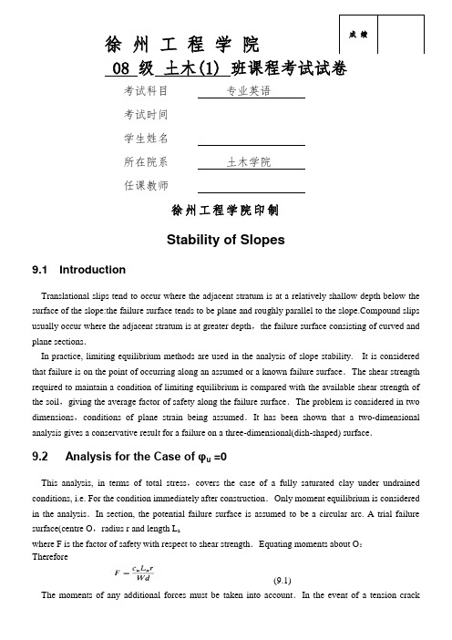
成绩徐州工程学院08 级土木(1) 班课程考试试卷考试科目专业英语考试时间学生姓名所在院系土木学院任课教师徐州工程学院印制Stability of Slopes9.1 IntroductionTranslational slips tend to occur where the adjacent stratum is at a relatively shallow depth below the surface of the slope:the failure surface tends to be plane and roughly parallel to the pound slips usually occur where the adjacent stratum is at greater depth,the failure surface consisting of curved and plane sections.In practice, limiting equilibrium methods are used in the analysis of slope stability. It is considered that failure is on the point of occurring along an assumed or a known failure surface.The shear strength required to maintain a condition of limiting equilibrium is compared with the available shear strength of the soil,giving the average factor of safety along the failure surface.The problem is considered in two dimensions,conditions of plane strain being assumed.It has been shown that a two-dimensional analysis gives a conservative result for a failure on a three-dimensional(dish-shaped) surface.9.2 Analysis for the Case of φu =0This analysis, in terms of total stress,covers the case of a fully saturated clay under undrained conditions, i.e. For the condition immediately after construction.Only moment equilibrium is considered in the analysis.In section, the potential failure surface is assumed to be a circular arc. A trial failure surface(centre O,radius r and length L awhere F is the factor of safety with respect to shear strength.Equating moments about O:Therefore(9.1)The moments of any additional forces must be taken into account.In the event of a tension crackdeveloping ,as shown in Fig.9.2,the arc length L a is shortened and a hydrostatic force will act normal to the crack if the crack fills with water.It is necessary to analyze the slope for a number of trial failure surfaces in order that the minimum factor of safety can be determined.Based on the principle of geometric similarity,Taylor[9.9]published stability coefficients for the analysis of homogeneous slopes in terms of total stress.For a slope of height H the stability coefficient (N s) for the failure surface along which the factor of safety is a minimum is(9.2)For the case ofφu =0,values of N ss depends on the slope angleβand the depth factor D,where DH is the depth to a firm stratum.Gibson and Morgenstern [9.3] published stability coefficients for slopes in normally consolidated clays in which the undrained strength c u(φu =0) varies linearly with depth.Example 9.1A 45°slope is excavated to a depth of 8 m in a deep layer of saturated clay of unit weight 19 kN/m3:the relevant shear strength parameters are c u =65 kN/m2 andφuIn Fig.9.4, the cross-sectional area ABCD is 70 m2.Weight of soil mass=70×19=1330kN/mThe centroid of ABCD is 4.5 m from O.The angle AOC is 89.5°and radius OC is 12.1 m.The arc length ABC is calculated as 18.9m.The factor of safety is given by:This is the factor of safety for the trial failure surface selected and is not necessarily the minimum factor of safety.The minimum factor of safety can be estimated by using Equation 9.2.From Fig.9.3,β=45°and assuming that D is large,the value of N s9.3 The Method of Slicesαand the height, measured on the centre-1ine,is h. The factor of safety is defined as the ratio of the available shear strength(τf)to the shear strength(τm) which must be mobilized to maintain a condition of limiting equilibrium, i.e.The factor of safety is taken to be the same for each slice,implying that there must be mutual support between slices,i.e. forces must act between the slices.The forces (per unit dimension normal to the section) acting on a slice are:1.The total weight of the slice,W=γb h (γsat where appropriate).2.The total normal force on the base,N (equal to σl).In general thisforce has two components,the effective normal force N'(equal toσ'l ) and the boundary water force U(equal to ul ),where u is the pore water pressure at the centre of the base and l is the length of the base.3.The shear force on the base,T=τm l.4.The total normal forces on the sides, E1 and E2.5.The shear forces on the sides,X1 and X2.Any external forces must also be included in the analysis.The problem is statically indeterminate and in order to obtain a solution assumptions must be made regarding the interslice forces E and X:the resulting solution for factor of safety is not exact.Considering moments about O,the sum of the moments of the shear forces T on the failure arc AC must equal the moment of the weight of the soil mass ABCD.For any slice the lever arm of W is rsinα,therefore∑Tr=∑Wr sinαNow,For an analysis in terms of effective stress,Or(9.3)where L a is the arc length AC.Equation 9.3 is exact but approximations are introduced in determining the forces N'.For a given failure arc the value of F will depend on the way in which the forces N' areestimated.The Fellenius SolutionIn this solution it is assumed that for each slice the resultant of the interslice forces is zero.The solution involves resolving the forces on each slice normal to the base,i.e.N'=WCOSα-ulHence the factor of safety in terms of effective stress (Equation 9.3) is given by(9.4)The components WCOSαand Wsinαcan be determined graphically for each slice.Alternatively,the value of αcan be measured or calculated.Again,a series of trial failure surfaces must be chosen in order to obtain the minimum factor of safety.This solution underestimates the factor of safety:the error,compared with more accurate methods of analysis,is usually within the range 5-2%.For an analysis in terms of total stress the parameters C u andφu are used and the value of u in Equation 9.4 is zero.If φu=0 ,the factor of safety is given by(9.5)As N’ does not appear in Equation 9.5 an exact value of F is obtained.The Bishop Simplified SolutionIn this solution it is assumed that the resultant forces on the sides of theslices are horizontal,i.e.X l-X2=0For equilibrium the shear force on the base of any slice isResolving forces in the vertical direction:(9.6)It is convenient to substitutel=b secαFrom Equation 9.3,after some rearrangement,(9.7)The pore water pressure can be related to the total ‘fill pressure’ at anypoint by means of the dimensionless pore pressure ratio,defined as(9.8)(γsat where appropriate).For any slice,Hence Equation 9.7 can be written:(9.9)As the factor of safety occurs on both sides of Equation 9.9,a process of successive approximation must be used to obtain a solution but convergence is rapid.Due to the repetitive nature of the calculations and the need to select an adequate number of trial failure surfaces,the method of slices is particularly suitable for solution by computer.More complex slope geometry and different soil strata can be introduced.In most problems the value of the pore pressure ratio r u is not constant over the whole failure surface but,unless there are isolated regions of high pore pressure,an average value(weighted on an area basis) is normally used in design.Again,the factor of safety determined by this method is an underestimate but the error is unlikely to exceed 7%and in most cases is less than 2%.Spencer [9.8] proposed a method of analysis in which the resultant Interslice forces are parallel and in which both force and moment equilibrium are satisfied.Spencer showed that the accuracy of the Bishop simplified method,in which only moment equilibrium is satisfied, is due to the insensitivity of the moment equation to the slope of the interslice forces.Dimensionless stability coefficients for homogeneous slopes,based on Equation 9.9,have been published by Bishop and Morgenstern [9.2].It can be shown that for a given slope angle and given soil properties th e factor of safety varies linearly with γu and can thus be expressed asF=m-nγu(9.10)where,m and n are the stability coefficients.The coefficients,m and n arefunctions ofβ,φ’,the dimensionless number c'/γand the depth factor D.Example 9.2Using the Fellenius method of slices,determine the factor of safety,in terms of effective stress,of the slope shown in Fig.9.6 for the given failure surface.The unit weight of the soil,both above and below the water table,is 20 kN/m 3 and the relevant shear strength parameters are c’=10 kN/m2andφ’=29°. W) of each slice is given byW=γbh=20×1.5×h=30h kN/mThe height h for each slice is set off below the centre of the base and thenormal and tangential components hcosαand hsinαWcosα=30h cosαW sinα=30h sinαThe pore water pressure at the centre of the base of each slice is taken to beγw z w,where z w is the vertical distance of the centre point below the water table (as shown in figure).This procedure slightly overestimates t he pore water pressure which strictly should be) γw z e,where z e is the vertical distance below the point of intersection of the water table and the equipotential through the centre of the slice base.The error involved is on the safe side.The arc length (L a) is calculated as 14.35 mm.The results are given inTable 9.1∑Wcosα=30×17.50=525kN/m∑W sinα=30×8.45=254kN/m∑(wcos α-ul)=525—132=393kN/m9.4 Analysis of a Plane Translational SlipIt is assumed that the potential failure surface is parallel to the surface of the slope and is at a depth that is small compared with the length of the slope. The slope can then be considered as being of infinite length,with end effects being ignored.The slope is inclined at angle βmz (0<m<1)above the failure plane.Steady seepage is assumed to be taking place in a direction parallel to the slope.The forces on the sides of any vertical slice are equal and opposite and the stress conditions are the same at every point on the failure plane.In terms of effective stress,the shear strength of the soil along the failure plane isand the factor of safety isThe expressions forσ,τandμare:The following special cases are of interest.If c’=0 and m=0 (i.e. the soilbetween the surface and the failure plane is not fully saturated),then(9.11)If c’=0 and m=1(i.e. the water table coincides with the surface of the slope),then:(9.12)It should be noted that when c’=0 the factor of safety is independent ofthe depth z.If c’ is greater than zero,the factor of safety is a function of z, and βmay exceedφ’ provided z is less than a critical value.For a total stress analysis the shear strength parameters c u andφu are used with a zero value of u. Example 9.3A long natural slope in a fissured overconsolidated clay is inclined at 12°to the horizontal.The water table is at the surface and seepage is roughly parallel to the slope.A slip has developed on a plane parallel to the surface at a depth of 5 m.The saturated unit weight of the clay is 20 kN/m3.The peak strength parameters are c’=10 kN/m2andφ’=26°;the residual strength parameters are c r’=0 andφr’=18°.Determine the factor of safety alo ng the slip plane(a)in terms of the peak strength parameters (b)in terms of the residual strength parameters.With the water table at the surface(m=1),at any point on the slip plane,Using the peak strength parameters,Then the factor of safety is given byUsing the residual strength parameters,the factor of safety can beobtained from Equation 9.12:9.5 General Methods of AnalysisMorgenstern and Price[9.4]developed a general analysis in which all boundary and equilibrium conditions are satisfied and in which the failure surface may be any shape,circular,non-circular or compound.The soil mass above the failure plane is divided into sections by a number of vertical planes and the problem is rendered statically determinate by assuming a relationship between the forces E and X on the vertical boundaries between each section.This assumption is of the formX=λf(x)E (9.13)where f(x)is an arbitrary function describing the pattern in which the ratio X/E varies across the soil mas s andλis a scale factor.The value ofλis obtained as part of the solution along with the factor of safety F.The values of the forces E and X and the point of application of E can be determined at each vertical boundary.For any assumed function f(x) it is necessary to examine the solution in detail to ensure that it is physically reasonable (i.e. no shear failure or tension must be implied within the soil mass above the failure surface). The choice of the function f(x) does not appear to influence the computed value of F by more than about 5% and f(x)=l is a common assumption.The analysis involves a complex process of iteration for the values ofλ and F,described byMorgenstern and Price[9.5],and the use of a computer is essential.Bell [9.1] proposed a method of analysis in which all the conditions of equilibrium are satisfied and the assumed failure surface may be of any shape.The soil mass is divided into a number of vertical slices and statical determinacy is obtained by means of an assumed distribution of normal stress along the failure surface.Sarma [9.6] developed a method,based on the method of slices,in which the critical earthquake acceleration required to produce a condition of limiting equilibrium is determined.An assumed distribution of vertical interslice forces is used in the analysis.Again,all the conditions of equilibrium are satisfied and the assumed failure surface may be of any shape.The static factor of safety is the factor by which the shear strength of the soil must be reduced such that the critical acceleration is zero.The use of a computer is also essential for the Bell and Sarma methods and all solutions must be checked to ensure that they are physically acceptable.References[9.1]Bell,J,M.(1968):’General Slope Stability Analysis’, Journal ASCE,V01.94,No.SM6.:‘Stability Coefficients for Earth Slopes Geotechnique,.’,Vo1.1 5,No.1.‘A Numerical Method for Solving the Equations of Stability of General Slip Surfaces’Computer Journal,Voi.9,P.388.[9.6]Sarma,S.K. (1973):’Stability Analysis of Embankments and Slopes’,Geotechnique,Vo1.23,No.2.[9.7]Skempton,A.W.(1970):’First-Time Slides in Overconsolidated Clays’(Technical Note),[9.8]Spencer,E.(1 967):‘A Method of Analysis of the Stability of Embankments Assuming Parallel Inter-SliceForces’,Geotechnique,.[9.9]Taylor,D.W.(1937):’Stability of Earth Slopes’,Journal of the Boston Society of Civil Engineers,Vo1.24,No.3边坡稳定9.1 引言重力和渗透力易引起天然边坡、开挖形成的边坡、堤防边坡和土坝的不稳定性。
土木工程专业英语翻译

⼟⽊⼯程专业英语翻译第⼀单元Fundamentally, engineering is an end-product-oriented discipline that is innovative, cost-conscious and mindful of human factors. It is concerned with the creation of new entities, devices or methods of solution: a new process, a new material, an improved power source, a more efficient arrangement of tasks to accomplish a desired goal or a new structure. Engineering is also more often than not concerned with obtaining economical solutions. And, finally, human safety is always a key consideration.从根本上,⼯程是⼀个以最终产品为导向的⾏业,它具有创新、成本意识,同时也注意到⼈为因素。
它与创建新的实体、设备或解决⽅案有关:新⼯艺、新材料、⼀个改进的动⼒来源、任务的⼀项更有效地安排,⽤以完成所需的⽬标或创建⼀个新的结构。
⼯程是也不仅仅关⼼获得经济的解决⽅案。
最终,⼈类安全才是⼀个最重要的考虑因素。
Engineering is concerned with the use of abstract scientific ways of thinking and of defining real world problems. The use of idealizations and development of procedures for establishing bounds within which behavior can be ascertained are part of the process.⼯程关⼼的是,使⽤抽象的科学⽅法思考和定义现实世界的问题。
土木工程专业英语词汇

土木工程专业英语词汇土木工程专业英语词汇大全土木工程专业培养掌握各类土木工程学科的基本理论和基本知识,能在房屋建筑、地下建筑(含矿井建筑)、道路、隧道、桥梁建筑、水电站、港口及近海结构与设施、给水排水和地基处理等领域从事规划、设计、施工、管理和研究工作的高级工程技术人才。
以下是土木工程专业的专业英语词汇,一起来看看吧。
geotechnical engineering综合类大地工程back analysis method综合类反分析法foundation engineering综合类基础工程critical state soil mechanics综合类临界状态土力学numerical geomechanics综合类数值岩土力学soil, earth综合类土soil dynamics综合类土动力学soil mechanics综合类土力学geotechnical engineering综合类岩土工程stress path综合类应力路径stress path method综合类应力路径法metamorphic rock工程地质及勘察变质岩standard frost penetration工程地质及勘察标准冻深glacial deposit工程地质及勘察冰川沉积glacial deposit工程地质及勘察冰积层(台)eluvial soil, residual soil工程地质及勘察残积土beding工程地质及勘察层理feldspar工程地质及勘察长石sedimentary rock工程地质及勘察沉积岩confined water工程地质及勘察承压水secondary mineral工程地质及勘察次生矿物geological age工程地质及勘察地质年代geological map工程地质及勘察地质图groundwater工程地质及勘察地下水fault工程地质及勘察断层fracture structure工程地质及勘察断裂构造engineering geological exploration工程地质及勘察工程地质勘察marine deposit工程地质及勘察海积层(台)marine deposit工程地质及勘察海相沉积granite工程地质及勘察花岗岩landslide工程地质及勘察滑坡fossil工程地质及勘察化石chemical sedimentary rock工程地质及勘察化学沉积岩terrace工程地质及勘察阶地joint工程地质及勘察节理cleavage工程地质及勘察解理karst工程地质及勘察喀斯特hardness of minerals工程地质及勘察矿物硬度conglomerate工程地质及勘察砾岩flow slide工程地质及勘察流滑continental sedimentation工程地质及勘察陆相沉积mud flow, debris flow工程地质及勘察泥石流clay minerals工程地质及勘察年粘土矿物tuff工程地质及勘察凝灰岩ox-bow lake工程地质及勘察牛轭湖hypabyssal rock工程地质及勘察浅成岩ground water工程地质及勘察潜水intrusive rock工程地质及勘察侵入岩geotome工程地质及勘察取土器sandstone工程地质及勘察砂岩spit, sand spit工程地质及勘察砂嘴rock pressure工程地质及勘察山岩压力plutionic rock工程地质及勘察深成岩limestone工程地质及勘察石灰岩quartz工程地质及勘察石英rickle工程地质及勘察松散堆积物confined ground water工程地质及勘察围限地下水(台) lagoon工程地质及勘察泻湖rock burst工程地质及勘察岩爆attitude of rock工程地质及勘察岩层产状magmatic rock, igneous rock工程地质及勘察岩浆岩dike, dgke工程地质及勘察岩脉degree of rock weathering工程地质及勘察岩石风化程度structure of rock工程地质及勘察岩石构造texture of rock工程地质及勘察岩石结构rock mass工程地质及勘察岩体shale工程地质及勘察页岩primary mineral工程地质及勘察原生矿物mica工程地质及勘察云母rock-forming mineral工程地质及勘察造岩矿物fold, folding工程地质及勘察褶皱bore hole columnar section工程地质及勘察钻孔柱状图saturated soil土的分类饱和土overconsolidated soil土的分类超固结土dredger fill土的分类冲填土frozen soil, tjaele土的分类冻土unsaturated soil土的分类非饱和土dispersive soil土的分类分散性土silt, mo土的分类粉土silty clay土的分类粉质粘土kaolinite土的分类高岭石overconsolidated soil土的分类过压密土(台)red clay, adamic earth土的分类红粘土loess, huangtu(China)土的分类黄土montmorillonite土的.分类蒙脱石peat, bog muck土的分类泥炭clay土的分类年粘土cohesive soil, clayey soil土的分类年粘性土expansive soil, swelling soil土的分类膨胀土underconsolidated soil土的分类欠固结粘土zonal soil土的分类区域性土fill, artificial soil土的分类人工填土soft clay, mildclay, mickle土的分类软粘土sand土的分类砂土collapsible loess, slumping loess土的分类湿陷性黄土plain fill土的分类素填土plasticity chart土的分类塑性图stone, break stone, broken stone, channery, chat, crushed stone, deritus土的分类碎石土underconsolidated clay土的分类未压密土(台)cohesionless soil, frictional soil, non-cohesive soil土的分类无粘性土。
- 1、下载文档前请自行甄别文档内容的完整性,平台不提供额外的编辑、内容补充、找答案等附加服务。
- 2、"仅部分预览"的文档,不可在线预览部分如存在完整性等问题,可反馈申请退款(可完整预览的文档不适用该条件!)。
- 3、如文档侵犯您的权益,请联系客服反馈,我们会尽快为您处理(人工客服工作时间:9:00-18:30)。
土木工程专业英语翻译Ch 2 Overview of Engineering MechanicsAs we look around us we see a world full of ‘things’: machines, devices, tools; things that we have designed, 当我们环顾四周,我们可以看到充满物质的世界:机器,仪器,工具:这些被我设计、建造和使用过built and used; things made of wood, metals, ceramics, and plastics. We know from experience that some 的东西:这些东西是由木头,金属,陶瓷和塑料做成。
我们从经验可以知道一些东西比别的东things are better than others; they last longer, cost less, are quieter, look better, or are easier to use.比别的东西好:他们比较耐用,低成本,安静,看起来好点,或者使用比较简单。
Ideally, however, every such item has been designed according to some set of ‘functional requirements; as 不管怎么样,最理想的是这样一个东西都是被设计者所认为的那样根据某些“使用要求”设计出来的。
perceived by the designers—that is, it has been designed so as to answer the question, ‘Exactly what function也就是说他的设计是为了回答这些问题,确切的说它应该执行怎么样的功should it perform?’ In the world of engineering, the major function frequently is to support some type of 能?在工程的领域里,最主要的功能是经常支持一些由于重力,惯性,压力等作用产loading due to weight, inertia, pressure etc. From the beams in our homes to the wings of an airplane, there 生的荷载。
从我们家里的梁柱要飞机的双翼,这些都是由材料尺寸和must be an appropriate melding of materials, dimensions, and fastenings to produce structures that will紧固件适当的组合,从而生产的结构在合理成本和使用周期的基础上可靠的履行它的职责。
perform their functions reliably for a reasonably cost over a reasonable lifetime.In practice, engineering mechanics methods are used in two quite different ways:在实践中,工程力学方法用于两种完全不同的方式。
1. The development of any new device requires an interactive, iterative consideration of form, size, materials,任何新设计的发展要求都在尺寸,材料,荷载,耐久度,安全性和成本等方面进行交互、反复的考虑。
loads, durability, safety, and cost.。
2. When a device fails (unexpectedly) it is often necessary to carry out a study to pinpoint the cause of failure当一个设计以外的失败的时候,必须经常的展开研究去查明失败的原因和确定可能的校正措施。
and to identify potential corrective measures. Our best designs often evolve through a successive elimination of 我们最好的设计是经常通过逐渐的消除缺点来实现的。
weak points.To many engineers, both of the above processes can prove to be absolutely fascinating and enjoyable, not to 对于许多工程师,上述的过程被证明它是极具吸引力和令人愉悦的,更不用说(有时)是有利可图的。
mention (at times) lucrative.In any ‘real’ problem there is never sufficient good, useful information; we seldom know the actual loads and 在任何真正的问题当中从未有足够好的,有用的信息,我们很少知道实际的荷载和任何精确的工作条operating conditions with any precision, and the analyses are seldom exact. While our mathematics may 件。
并且分析的结构很少是精确的。
虽然我们的数学可以很精确,precise, the overall analysis is generally only approximate, anddifferent skilled people can obtain different 所有的分析结果一般仅仅是近似的,和不同掌握技术的人可以获得不同的解决方案。
solutions. In the study of engineering mechanics most of the problems will be sufficiently ‘idealized’ to 在工程力学的研究当中,大多数的问题都将被足够的理想化,以便允许得到唯一的答案。
permit unique solutions, but it should be clear that the ‘real world’ is far less idealized, and that you usually但是我们应该清楚意识到“真实的世界”远不是理想化的,你通常不得不执行will have to perform some idealization in order to obtain a solution.一些理想化以便获得答案。
The technical areas we will consider are frequently called ‘statics’ and ‘strength of materials’, ‘statics’我们将考虑的技术领域通常叫做“静力学”和“材料力学”。
静力学是指力作用于静止物体上的一种referring to the study of forces acting on stationary devices, and ‘strength of materials’ referring to the effects 研究,“材料力学”是指那些力作用在结构上的of those forces on the structure (deformation, loading limits, etc.).影响(变形,荷载极限等)。
While a great many devices are not, in fact, static, the methods developed here are perfectly applicable to然而在实际上许多的设备并不是静力学的问题,如果额外的荷载被考虑,这里的研究方法完全适用于dynamic situations if the extra loadings associated with the dynamics are taken into account (we shall briefly 动力学情形,以至于在动力的情况下也被考虑在内(我们应该简单的提一下是怎么样被做到的)mention how this is done). Whenever the dynamic forces are small relative to the static loadings, the system只要动力学的力相对于静力荷载来说很小,这个系统通常可以考虑为静力学is usually considered to be static.的问题。
In engineering mechanics, we will begin to appreciate the various types of approximations that are inherent在工程力学里,我们将开始正确评价各种类型在实际问题中本身就存在的近似方法。
in any real problem:Primarily, we will be discussing things which are in ‘equilibrium’, i.e., not accelerating. However, if we look 首先,我们将会讨论处于平衡及不产生加速度的物体。
然而如果我们看的够仔细,所有东西是运动的。
closely enough, everything is accelerating.We will consider many structural members to ‘weightless’ but they never are.我们会把一些结构构件考虑成失重,但他们从来都不是。
We will deal with forces that act at a ‘point’—but all forces act over an area.我们要处理的力作用在一个点上——但是所有的力作用在一个区域上。
We will consider some parts to be ‘rigid’—but all bodies will deform under load.我们会认为一些结构是刚性的——但是所有的构件都在何在下变形。