Intl'2000系统说明书(f)
第3册__2000TA连接说明1215
CASNUC 2000TA数控系统用户手册连接维修说明(PLC版本V14.0.0.X标准版)北京航天数控系统有限公司BEIJING AEROSPACE NUMERICAL CONTROL SYSTEM Co ,L td.北京航天数控系统有限公司质量方针:追求顾客满意,持续改进创新,严格过程控制,全员质量管理,打造航天品质产品,创“航天数控”名牌。
企业精神:诚信、团队、图强、变革。
联系我们:公司地址:北京市海淀区永定路甲51号邮政地址:北京142信箱86分箱邮政编码:100854电话:************公司网址:售后服务电话:************产品销售中心:************、************服务质量投诉:************传真:************、************E-mail:*****************.cn请仔细阅读并妥善保存本手册注意事项:操作者必须在完全熟悉本套说明书及由机床制造厂提供的相关说明的内容后,才能操作机床或编制加工程序。
用户在使用中必须遵守说明书中的规定,这是安全、正确使用CNC装置必需的准备工作。
CASNUC 2000TA车床数控系统,简称2000TA。
2000TA用户手册概述(第四版)本用户手册共分3册:第一册:2000TA操作说明第二册:2000TA编程说明第三册:2000TA连接、维修说明关于本手册的声明:手册及产品的规格如果发生变化,公司不作另行通知;在本说明书中我们将对涉及到的各个方面尽力叙述。
尽管如此,还是不能对所有不必做的和不能做的事情全部进行叙述,因此不能将本书中没有特别指明为“可能”的事件视为“不可能”的事件。
请仔细阅读本说明,并妥善保存。
概述本章描述了CASNUC 2000TA数控系统的CNC控制单元与伺服驱动装置、主轴驱动装置以及机床电气相连接所需的机械结构、电气接口的结构和规格。
请在动手实施连接之前详细阅读本章,以避免产生意外问题。
RCP-2000系列2000W前置电源系统说明书
RCP-2000系列
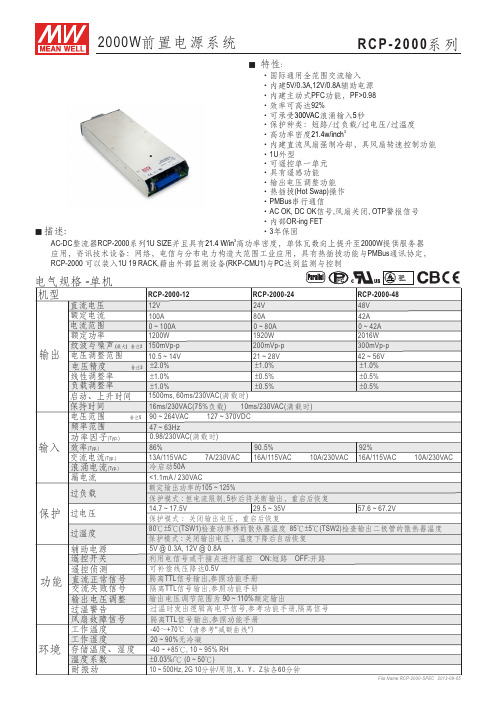
2000W 前置电源系统
‧国际通用全范围交流输入‧内建5V/0.3A,12V/0.8A 辅助电源‧内建主动式PFC 功能,PF>0.98‧效率可高达92%
‧可承受浪涌输入秒
‧保护种类:短路/过负载/过电压/过温度
‧高功率密度‧内建直流风扇强制冷却,具风扇转速控制功能‧1U 外型
‧可遥控单一单元‧具有遥感功能‧输出电压调整功能‧热插拔(Hot Swap)操作‧PMBus 串行通信
‧AC OK, DC OK 信号,风扇关闭, OTP 警报信号‧内部OR-ing FET ‧3年保固300VAC 53
21.4w/inch
■ 特性:
■ 描述:
AC-DC 整流器RCP-2000系列1U SIZE 并且具有高功率密度,单体瓦数向上提升至2000W 提供服务器应用,资讯技术设备:网络,电信与分布电力构造大范围工业应用,具有热插拔功能与PMBus 通讯协定, RCP-2000 可以装入1U 19 RACK,籍由外部监测设备(RKP-CMU1)与PC 达到监测与控制
3
21.4 W/in
File Name:RCP-2000-SPEC 2013-08-05。
UT-2000使用说明书-6

第二章操作UT-2000型微机综合操作系统,是用于电力系统防误倒闸操作,实现变电站综合自动化的一种新型装置。
实现了监控系统、五防闭锁系统和操作系统等多方面的统一,具有对电气设备进行集中监测、控制、操作、遥信遥测量显示、报警等功能。
该系统简单、实用、可靠,具有较好的性能价格比。
特别适合无人或少人值班的发电厂、变电站、工矿企业的单元控制室和网控室。
UT-2000 型微机综合操作系统是由综合操作屏、TXJ-1型通讯管理机、WJBS-5F型工控主机、KBQE-1型开关闭锁控制器、DNBS-1B型电脑钥匙、DNBS-2A电编码锁、DNBS-3型机械编码锁和其它部件组成。
其操作界面为综合操作屏,通过屏面控制开关,可置该系统于返回屏工作方式、模拟屏工作方式和操作屏工作方式。
下面就介绍一下UT-2000 型微机综合操作系统在不同工作方式下的使用方法。
1.返回运行方式当综合操作系统没有操作票时,UT-2000型微机综合操作系统自动进入返回运行方式,此时该系统相当于一套实时显示的返回屏。
根据微机监控系统通过TXJ-1通讯管理机传给UT-2000型微机综合操作系统的遥信、遥测量利用灯开关和数码显示表头在屏面上实时显示相关设备状态和电量数据(同地调屏类似)。
当全站检修时,可将总解锁开关扳至合位,此时显示器显示“全站总解锁”,同时所有由开关闭锁控制器控制的断路器均解锁,如为KBQD-1型运行人员可以直接在控制屏上操作,如为KBQE-1型运行人员可以直接在综合操作屏上进行操作。
2.模拟运行方式在返回运行(反馈)状态下按模拟开关,UT-2000型微机综合操作系统进入模拟运行方式,此时该系统相当于一套五防闭锁模拟屏。
操作步骤如下:2.1接通启动开关,依次显示“UT-2000型微机综合操作系统版本X.X”,“装置自检”,自检正确后显示“装置自检结束”。
2.2接着显示“开关对位态”,向监控系统请求遥信,并按遥信量,系统记忆及KBQ 状态进行操作屏开关对位。
FDS-2000电子测试仪操作手册说明书
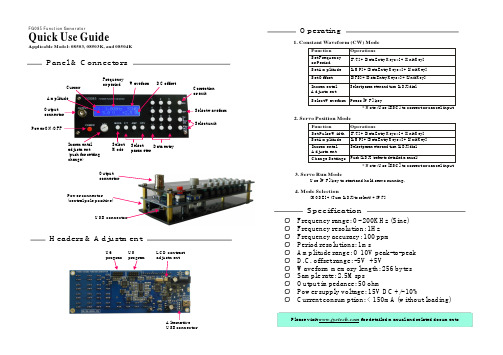
Function Set Pulse Width Set Amplitude Incremental Adjustment Change Settings
Operations
[F/T] + [Data Entry Keys *] + [Unit Key] [AMP] + [Data Entry Keys *] + [Unit Key] Select parameter and turn [ADJ] dial
Incremental adjustment (push for setting change)
Select Select Data entry Mode parameter
Output connector
Power connector (central pole positive)
USB connector
Correction or exit
Select waveform Select unit
Headers & Adjustment
U6
U5
program program
LCD conBconnector
Operating
1. Constant Waveform (CW) Mode
Please visit for detailed manual and related documents
[MODE] + {Turn [ADJ] to select} + [WF]
Specification
Ø Frequency range: 0 - 200KHz (Sine) Ø Frequency resolution: 1Hz Ø Frequency accuracy: 100 ppm Ø Period resolutions: 1ms Ø Amplitude range: 0 10V peak-to-peak Ø D.C. offset range: -5V +5V Ø Waveform memory length: 256 bytes Ø Sample rate: 2.5Msps Ø Output impedance: 50 ohm Ø Power supply voltage: 15V DC +/- 10% Ø Current consumption: < 150mA (without loading)
IMU2000配电终端产品说明书
PIMU2000配电终端产品说明书V2.0浙江智拓智能技术有限公司2012-02目录1. 概述 (3)1.1. 概述 (3)1.2. 硬件结构 (3)2. 模件功能介绍 (5)2.1. 模件类型和装置配置图 (5)2.2. CPU模件 (5)2.3. DSP模件 (7)2.4. 显示模件 (9)2.5. 电源模件 (10)2.6. 母线模件 (10)2.7. 模拟量输入接口模件1(YC板) (11)2.8. 模拟量输入接口模件2(YC板) (11)2.9. 信号量输入接口模件(YX板) (11)2.10. 开关量输出接口模件(YK板) (12)2.11. CPU模件 (12)2.12. DSP模件 (14)1.3. 显示模件:M404-LCD (15)2.13. 电源模件:M400-PWR (16)2.14. 模拟量输入接口模件(YC板) (17)2.15. 信号量输入接口模件(YX板) (19)2.16. 开关量输出接口模件(YK板):M400-DO (20)1.概述1.1. 概述PIMU2000配电终端采用模块化设计,能够完成对配电开关的信息采集和控制;完成配电线路的遥测采集;实现配网线路故障检测;通过远程通信通道,如光纤、电缆、载波、GPRS/CDMA等,将信息传送至配电自动化系统子站或主站,同时接收来自子站或主站的控制命令,对配电开关进行遥控操作,从而实现对配电网的实时监控、故障识别故障隔离、网络重构等,减少配电网地停电时间,提高配网的供电可靠性。
1.2. 硬件结构(1) PIMU2000配电终端一般配置➢测控单元:交采、开入、开出、通讯、显示、存储等功能。
➢机柜:各地区要求不同机柜结构也不同。
➢电池充放电管理模块:各地区要求不同,型号也不同。
➢备用电池:各地区要求不同,型号也不同。
➢远程通讯单元:一般由用户根据情况配置,要求提供电源、通讯及安装位置,GPRS方式时由厂家配备。
➢双路电源切换器:两路主电源输入,切换输出一路至电池充放电管理模块,同时产生24V直流电源至远程通讯装置➢其它辅助元件,如端子、空气开关、压板、连接电缆等(2) PIMU2000配电终端测控单元一般配置➢电源模件:产生终端其它功能模件需要的DC3.3V、DC5V、DC12V、-DC12V、DC24V电源;同时集成了24路YX输入。
Perten Glutomatic 2000系统:国际标准糕面测试说明书

GLUTEN
QUANTITY AND
QUALITY
Perten Glutomatic ® 2000 System
The International Standard Gluten Test
WORLD STANDARD TEST FOR GLUTEN IN FLOUR, WHEAT, DURUM, AND SEMOLINA
Size H x D x W and weight
Glutomatic 2000: 378 x 353 x 288 mm,18 kg Centrifuge 2010: 203 x 270 x 224 mm, 7 kg Glutork 2020: 90 x 255 x 200 mm, 2 kg
GM 2000 touch screen 7 inches, capacitive
SPECIFICATIONS
Products
Wheat meal, wheat flour, durum meal, semolina, durum flour and vital wheat gluten
Parameters
Wet Gluten Content, Gluten Index, Dry Gluten Content and Gluten Water Binding
• Segregation: Identify and separate high quality grain and flour to maximize its value.
• Easy Sample Preparation: No sample conditioning or chemicals required.
For a complete listctUs
InterChangeVS 2000产品简介说明书

Product OverviewThe InterChangeVS 2000 is an analog multimodem virtual server that can be stacked or mounted in a rack. This VS2000 contains eight 33.6K bps modem ports. VS2000 features include:•Eight RJ11 modem ports ready to connect to yourphone lines•Diagnostic LEDsVS-Link software provides the following features, which are discussed in the VS2000 VS-Link Installation and Configuration Guide :•Backup server •“Hot-swapping”•Individual modem reset capability •Terminal program (WCOM32)•Port Monitor program (PORTMON)See the VS2000 VS-Link ™ Installation andConfiguration Guide for information about installing the software for this product and for reference information for the AT command set.Installing VS2000 HardwareUse the following procedure to connect the VS2000.1.Record the model and serial numbers of the VS2000.2.Optionally , mount the VS2000 into the rack usingthe enclosed mounting brackets. The unit isdesigned to install in the rack with the front or back of the unit facing the front of the rack.Warning:If mounting the VS2000 into a rack mountunit, make sure the rack is not top heavy.3.Connect the cable from the appropriate Ethernetconnection (10Base-T or AUI) on the VS2000 to your server or Ethernet hub.Note:If connecting the VS2000 directly to the server, anEthernet crossover cable is required.Note:4.Connect the power cord.5.Go to the Power-On Diagnostics discussion.Power-On DiagnosticsWhen you switch a VS2000 on, it performs a self-diagnostic. The results are displayed via the LED lights on the back panel. If the unit is working correctly, the following events should take place:1.Turn the power switch to the On position.2.All LEDs should light up briefly , to show that theyare working.3.Both 10Base-T lights should remain lit after theport LEDs go out, while the unit establishes the Ethernet connection and polarity .4.If using 10Base-T cabling, the lower LED remainslit to indicate that the Ethernet connection is established and polarity is correct.5.The Port 2 LED begins flashing, to indicate that theVS2000 is waiting for the server to initiate VS-Link communications.Note:The following steps only occur after you haveinstalled the VS-Link software. Use the VS2000 VS-Link Installation and Configuration Guide for software installation information.After installing the software, turn off the VS2000 and verify the full diagnostics sequence.6.The upper 10Base-T LED flashes briefly , as theserver acquires control of the VS2000.7.The port LEDs begin flashing in a “sweeping”sequence, to indicate that the unit is operating normally .Note:See the following tables if you are not seeing theLED sweeping sequence activity.Serial Number*VS2000 Network Address*00 C0 4E* Identification tags are located on the back panel. You can write this information on the blank sticker shipped with the VS2000.Server RunningVS-LinkEthernet Connectionto Server or Ethernet HubInterChangeVS™ 2000 V .34 North AmericaHardware Installation CardNote:If using an AUI connection to the server, you candetermine proper polarity by using an AUI to 10Base-T converter box.Modem CablesThe VS2000 modem ports use standard telephone-type unshielded twisted-pair cables with RJ11 modular connectors. These cables can be purchased anywhere commercial or consumer telephone products are sold.If you choose to build your own cables, use the following information:The connector pinouts are as shown below:When building cables, use Category 3 (or better) unshielded wiring.Ethernet Crossover CableIf you are connecting from the VS2000 10Base-T connector directly to the NIC card in the server, you need a crossover cable, wired as follows:Remote ConnectorThe DB9 port labeled “Remote” is reserved for Comtrol Corporation repair and maintenance use. No user-accessible signals are present on this port.Operating ConditionsThis table illustrates VS2000 operating conditions:Electromagnetic ComplianceThis table lists electromagnetic compliance certifications:LEDLight 10Base-T LED DescriptionU p p e rFlashes Briefly During the power on cycle (first fewseconds after the power is turned on), this LED flashes briefly to display linkpolarity on the 10Base-T connection.U p p e rFlashing The light flashes briefly duringtransmissions as a general indicator ofactivity.L o w e r On VS2000 is correctly attached to the LAN by the RJ45 10Base-T connector. L o w e r OffVS2000 is not connected to the LAN properly or it is connected to the AUI port.Indicator Ports 1 through 8 LED Description Flash BrieflyAll LEDs light briefly during the power-on sequence and then turn off.1 LED Lit*RAM self-test failure or mainboard error.2 LEDs Lit*Ethernet hardware initialization failure.3 LEDs Lit*A hardware self-test failure.4 LEDs Lit*A flash memory configuration error.AllFlashing/Individual Flashing All LEDs on for about 0.5 seconds then one or more individual port LEDs on for about 0.5 seconds indicates that the individual port or ports, whose LED is flashing, encountered a problem duringport/modem initialization.*The LEDs light up for a about a minute and then the hardware resets and the same cycle repeats.Pins RJ11 Connector Signals1Not used 2Ring 3Tip 4Not usedPin 1Pin 4Table 1. Ethernet Crossover CablePin Connects to Pin13263162Environmental Condition Value Air temperature:System on System off 0 to 40o C -20 to 85o C Altitude0 to 10,000 feet Humidity (non-condensing):System on System off8% to 80%20% to 80%Electromagnetic Compliance Status Canadian EMC requirements Yes FCC Class A certification Yes FCC Part 68 certification Yes Ringer Equivalency Number 0.8B UL Listed YesSurge protectionESD surge protection exceeding 20 KVPin 1Pin 8ReceptaclePin 1Hardware SpecificationsThe following table illustrates hardware specifications:Safety NoticesInstallation of inside wire may bring you close to electrical wire, conduit, terminals and other electrical facilities. Extreme caution must be used to avoid electrical shock from such facilities. Avoid contact with electrical current by following these guidelines:•Use tools with insulated handles.•Do not place telephone wiring or connections in any conduit, outlet or junction box containing electrical wiring.Note:Do not work on your telephone wiring at all if you wear a pacemaker. Telephone lines carryelectrical current.•Telephone wiring must be at least 6 feet from bare power wiring or lightning rods and associated wires, and at least 6 inches from other wire (antennawires, doorbell wires, wires from transformers toneon signs), steam or hot water pipes, and heating ducts.•Before working with existing inside wiring, check all electrical outlets for a square telephone dial lighttransformer and unplug it from the electrical outlet.Failure to unplug all telephone transformers cancause electrical shock.•Do not place a jack where it would allow a person to use the telephone while in a bathtub, shower,swimming pool, or similar hazardous location.•Protectors and grounding wire placed by the service provider must not be connected to, removed, ormodified by the customer.CAUTION:Do not touch telephone wiring duringlightning!FCC NoticesRadio Frequency Interference (RFI) (FCC 15.105) The VS2000 has been tested and found to comply with the limits for Class A digital devices pursuant to Part 15 of the Federal Communications Commission rules.The VS2000 generates, uses, and can radiate radio frequency energy, and if not installed and used in accordance with this card, may cause harmful interference to radio communications. However, there is no guarantee that interference will not occur in a particular installation. If this equipment does cause harmful interference to radio or television reception, which can be determined by turning the equipment off and on, you are encouraged to try and correct the interference by one or more of the following measures:•Reorient or relocate the receiving antenna.•Increase the distance between the equipment and the receiver.•Connect the equipment into an outlet on a circuit different from that to which the receiver isconnected.•Consult the dealer or an experienced radio/TV technician for help.Labeling Requirements (FCC 15.19)The VS2000 complies with part 15 of FCC rules. Operation is subject to the following two conditions: •This device may not cause harmful interference, and •This device must accept any interference received, including interference that may cause undesiredoperation.Modifications (FCC 15.21)Changes or modifications to this equipment not expressly approved by Comtrol Corporation may void the user's authority to operate this equipment.Cables (FCC 15.27)This equipment is certified for Class A operation when used with unshielded cables.FCC Part 68 Notice1.This equipment complies with Part 68 of FCC rules.On the bottom panel of the unit is a label containing the FCC registration number, ringer equivalencenumber, and the USOC jack code.2.The VS2000 uses FCC compliant modular plugs, itis designed to be connected to the telephone network or premises wiring using a compatible modular jack which is FCC Part 68 compliant.3.If this equipment causes harm to the telephonenetwork, the telephone company will notify you inadvance that temporary discontinuance of servicemay be required. But, if advance notice is notpractical, the telephone company will notify you as soon as possible. Also you will be advised of yourright to file a complaint with the FCC, if you believe it is necessary.4.The telephone company may make changes in itsfacilities, equipment, operations, or procedures that could affect the operation of the equipment. If this happens, the telephone company will provideadvance notice in order for you to make necessarymodifications in order to maintain uninterruptedservice.5.If the equipment is causing harm to the network,the telephone company may request you to remove the equipment from the network until the problem is resolved. If so, contact Comtrol Corporation at651-631-7654.Topic HardwareSpecifications Modems/VS20008Number of VS2000/server Dependent on operatingsystemTelco connector RJ11Baud rate 33.6K bps (Maximum)Device driver control: Data bitsParityStop bits7 or 8 Odd, Even, None1 or 2Heat output81.84 BTU/Hr Mean time between failures7 years Power consumption24 W Current consumption200 mA (at 120 VAC) Line voltage100 - 240 VACEthernet host interface AUI or10Base-T (10 MB/sec) Weight 5 lbs Dimensions (without feet orbrackets)16.75” x 11” x 1.75”6.No repairs are to be made by you. Repairs are to bemade only by Comtrol or its licensees.Unauthorized repairs void the warranty and theregistration.7.This equipment cannot be used for public coinservice provided by the telephone company.Connection to Party Line Service is subject to state tariffs. (Contact the state public utility commission, public service commission, or corporationcommission for information.)VS2000 - CanadaThe VS2000 connects directly to off-premises Common Carrier facilities using the standard two-wire telephone connection. In some cases, the building’s inside wiring associated with a single line individual server may be extended by means of a certified connector assembly (telephone extension card).NOTICE: The Industry Canada label identifies certified equipment. This certification means the equipment meets telecommunications network protective, operational, and safety requirements as prescribed in the appropriate Terminal Equipment Technical Requirements document(s). The Department does not guarantee the equipment will operate to the user’s satisfaction.Before installing this equipment, users should ensure that it is permissible to be connected to the facilities of the local telecommunications company. The equipment must also be installed using an acceptable method of connection. The customer should be aware that compliance with the above conditions may not prevent degradation of service in some situations.Repairs to certified equipment should be coordinated by a representative designated by the supplier. Any repairs or alterations made by the user to this equipment, or equipment malfunctions, may give the telecommunications company cause to request the user to disconnect the equipment.Users should ensure for their own protection that the electrical ground connections of the power utility, telephone lines, and internal metallic water pipe system, if present, are connected together. This precaution may be particularly important in rural areas. CAUTION: Users should not attempt to make such connections themselves, but should contact the appropriate electric inspection authority or electrician, as appropriate.NOTICE: The Ringer Equivalence Number (REN) assigned to each terminal device provides an indication of the maximum number of terminals allowed to be connected to a telephone interface. The termination on an interface may consist of any combination of devices, subject only to the requirement that the sum of the Ringer Equivalence Numbers of all the devices does not exceed 5.This digital apparatus meets the Class A limits for radio noise for digital apparatus set out in the interference-causing equipment standard entitled: “Digital Apparatus,” ICES-003 of Industry Canada.When connecting the VS2000 to the telephone service, avoid contact with the telecommunications lead wire. Grasp the insulated part of the jack, and do not contact the back of the circuit board. Telephone wiring can carry dangerous voltages from electrical faults or lightning.External WiringAny external communications wiring you may install needs to be constructed to all relevant electrical codes. In the United States this is the National Electrical Code Article 800. Contact a licensed electrician for details. Canada - Return CenterIn Canada, contact the following Return Center: Gandacar Consulting, Ltd189 Lake Avenue EastCarlton Place, OntarioCanada K7C 1J7 Phone: 800-563-5102 Technical SupportIf you need technical support, contact Comtrol using one of the following methods.• email: *******************• FAX: (651) 631-8117• Phone: (651) 631-7654• FTP Site: ftp://• Web Site: Comtrol has a staff of technical support representatives to help you.First Edition, July 7, 1998Copyright © 1998. Comtrol Corporation.All Rights Reserved.Comtrol Corporation makes no representations or warranties with regard to the contents of this document or to the suitability of the Comtrol product for any particular purpose. Specifications subject to change without notice. Some software or features may not be available at the time of publication. Contact your reseller for current product information.Trademark NoticesComtrol, InterChangeVS, and VS-Link are trademarks of Comtrol Corporation.Other product names mentioned herein may be trademarks and/or registered trademarks of their respective owners.6631。
PCS2000系列微机变电站综合自动化系统技术说明书

第一章.系统概述PCS-2000型分层分布式变电站综合自动化系统是在总结以往成功投运200多个变电站的5000多个单元设备的基础上,吸取国内外微机保护和综合自动化技术之长,开发的新一代高性价比的变电站综合自动化系统。
该系统安照分层、分布式控制系统的设计原则,符合国际电工委员会IEC/TC-57电力系统控制与通信技术委员会对变电站监控系统的分层建议,符合我国无人值班变电站设计技术规程(DL/T5103-1999)和变电站监控系统技术规范要求。
PCS-2000型分层分布式变电站综合自动化系统广泛适用于110Kv及以下电压等级变电站的新建及改造工程。
1.1 PCS-2000系统的分层、分布、分散式结构如下:分层:该系统分成两层:间隔层和站控层。
层与层之间相对独立,通过具有冗余结构的前置层设备连接通信。
间隔层设备包括保护设备、数据采集、控制设备及指示/显示部分等。
PCS-2000系统的间隔层由独立的保护测控单元装置组成,通过CAN网络互联,并与站控层通信。
PCS-2000系统的站控层由站级计算机构成,也可由多机组成网络,站控层通过通信管理机与间隔层通信,实现站级协调、优化控制和当地监控功能;同时实现与远方调度中心的通信。
由于采用了先进的当地监控系统,取代了模拟控制屏,使所有操作更安全、可靠。
同时也取消了中央信号控制屏,在相应单元装置上加上相应开关的就地操作和位置指示信号,作为开关后备操作与监视。
分布:PCS-2000的间隔层以站内一次设备(如一台主变或一条线路)间隔为对象,面向对象,综合分析变电站对信息的采集控制要求,分布式配置小型化、高可靠性的微机保护测控单元装置。
各间隔单元完全独立,通过先进的CAN网络互联。
在功能分配上,凡可以在本间隔单元就地完成的功能,不依赖通信网。
由于采用保护、测控一体化、小型化设计,屏柜的数量较传统设计大为减少。
分散:PCS-2000系统对35KV及以下电压等级的二次保护和监控单元设备,可选择就地分散安装在开关柜上,做到地理位置上的分散。
- 1、下载文档前请自行甄别文档内容的完整性,平台不提供额外的编辑、内容补充、找答案等附加服务。
- 2、"仅部分预览"的文档,不可在线预览部分如存在完整性等问题,可反馈申请退款(可完整预览的文档不适用该条件!)。
- 3、如文档侵犯您的权益,请联系客服反馈,我们会尽快为您处理(人工客服工作时间:9:00-18:30)。
INTL’2000电梯控制系统调试维护说明书Intl’2000 电梯控制系统调试维护说明书Elevator Control System User Guide目录序言第一章控制系统的功能 (1)1.1 基本功能 (1)1.2 特殊功能 (3)1.3 安全保护功能 (5)1.4 可选功能 (5)第二章控制系统的组成与安装 (6)2.1 控制系统的组成 (6)2.2 控制系统的安装 (11)第三章液晶界面操作及参数说明 (18)3.1 概述 (18)3.2 键操作说明 (18)3.3 液晶显示流程图及参数说明 (19)3.4 窗口及操作说明 (27)第四章系统的调试与运行 (47)4.1 通电前的检查 (49)4.2 通电和检查 (50)4.3 系统参数设定 (50)4.4 慢车试运行 (51)4.5 井道自学习运行 (51)4.6 快车试运行 (52)4.7 电梯舒适感调整 (52)4.8 平层精度的调整 (58)4.9 端站安装位置的确认 (58)附录一异步电机控制柜安川G7A变频器参数设置表 (59)附录二同步电机控制柜安川676GL5-IP变频器参数设置表 (61)附录三同步电梯控制柜西威变频器参数设置表 (63)附录四同步电机控制柜CT-ES变频器参数设置表 (68)附录五故障代码及说明 (71)附录六井道自学习故障码表 (72)序言INTL’2000电梯控制系统是我公司推出的智能化更高、功能更强、调试与维护更方便的高技术产品。
它除了具有一般电梯控制系统的基本功能外,在系统参数设置、电梯功能选择、电梯调试与维护、现场适应能力等各方面有独到之处。
本系统的基本控制方式为串行通讯(CAN总线)与变频调速;可满足电梯楼层64层以下,电梯速度小于4米/秒,包括永磁同步电机在内的各种电梯电机的控制要求。
INTL’2000型电梯电脑控制器的主板、操纵盘板、呼梯板的核心芯片是国际著名工业用单片机制造商FUJITSU的内部具有32位处理器的高端产品,集成度、可靠性堪称世界一流;软件设计充分体现了功能齐备,参数设置界面层次分明,调试及故障诊断信息充分,抗干扰能力强及干扰强度评价独具匠心的技术特点。
对电梯控制系统以外的电气元件设计了诊断与检测界面。
使电梯故障判断有的放矢,真正使该电梯控制系统做到了高性能与可靠性的完美统一,高水平与实用性的完美统一,高科技与应用简便的完美统一。
警告用户在使用本系统时应严格按照国家电梯标准的要求进行作业,并且详细阅读本系统所使用的《变频器》说明书。
上述文件中涉及人身安全的部分均作为本系统对使用者的警告。
注意说明书中的符号与框图可能有更改,用户应以随机原理图为准。
第一章控制系统的功能1.1 基本功能1.1.1 检修运行系统具有三个检修开关。
优先级别由高至低分别为:轿顶检修开关,轿内检修开关,控制柜检修开关。
优先级别高的检修开关置位后,优先级别低的检修开关将不起作用。
将系统设置为检修状态后,按下相应位置的“上行”或“下行”按钮,电梯会以检修速度向上或向下运行,松开按钮后停止。
系统在检修状态时开关门为点动方式。
1.1.2 自动运行(无司机运行)将控制柜上的开关设置为“正常”、操纵盘上的开关设置为“自动”、在另外两个检修开关没有动作的情况下,电梯将工作在自动状态。
登记外呼梯信号按照顺向截车、反向最高(低)截车的原则运行;平层停车后自动开门,延时一段时间(可以通过“开门保持时间”设置)后自动关门,如果自动关门时间未到,也可按手动关门按钮提前关门;本层呼梯自动开门;所有登记指令服务完毕后,电梯将自动延时返回待梯层。
1.1.3 有司机运行将控制柜上的开关设置为“正常”、操纵盘上的开关设置为“司机”、在另外两个检修开关没有动作的情况下,电梯将工作在司机状态。
在司机状态下,系统只登记内选信号。
如有外呼信号,操纵盘内对应层的内选灯闪动;顺向外呼自动截车;平层停车后自动开门,但不自动关门,须由司机按动关门按钮。
1.1.4 上电自动开门每次电梯上电,如轿厢正在门区,轿门将自动打开。
1.1.5 自动关门延时(开门保持时间)设置自动运行时,电梯到站自动开门,延时后自动关门。
延时时间通过“开门保持时间”参数设定。
当只有内选信号停车时,延时时间为T(所设时间)当只有外呼信号停车时,延时时间为T-2秒,当既有内选又有外呼信号停车时,延时时间为2T 秒。
1.1.6 本层呼梯开门如电梯未起动且门已关上或正在关闭,按本层呼梯,轿门自动打开。
延时时间通过“开门保持时间”参数设定。
1.1.7 安全触板或光幕保护关门时安全触板或光幕动作,关门动作马上停止,开门后重新关门;如安全触板或光幕动作不消除则不关门。
1.1.8 满载直驶及超载不关门若电梯装有称重装置,满载时电梯只响应内选,不响应外呼。
如电梯超载,则电梯门打开、超载灯亮、蜂鸣器响、操纵盘显示“OVER LOAD”并且关门按钮无效,超载消除后自动恢复正常。
1.1.9 司机控制直驶有司机状态运行时,按下直驶按钮则电梯只响应内选,不响应外呼。
1.1.10 运行状态显示电梯运行的状态、方向、所处楼层、轿门的状态、负载状况及故障等信息可通过液晶显示器显示。
1.1.11 自动开关照明如15分钟电梯无人使用,轿厢内照明将自动熄灭。
接到任何召呼命令后自动打开。
1.1.12 消防消防开关闭合后系统进入消防运行:系统将清除所有外呼及内选信号,自动返回消防基站,常开门。
如电梯正在反方向运行,则就近层停车不开门返回消防基站,常开门。
当电梯返回消防基站后,输出消防联动信号。
具有两种消防运行模式供用户选择:一、当设置为消防模式1时,电梯返回消防基站并处于停用状态不再运行。
二、当设置为消防模式0时:1.外呼梯失效。
2。
电梯在消防层时处于开门状态。
当需要运行时,消防人员应首先选中目的楼层的内指令,然后按住关门按钮,直至门关好电梯运行。
如在门关好前松开,电梯立即开门。
3.当电梯到达目的楼层不自动开门,需按住开门按钮直至门开到位。
在门未开到位时松开,门立即关闭。
4.每次运行只能选定一个目的楼层。
1.1.13 故障时自动靠站如果电梯快车运行时发生故障停止在非门区,那么在安全回路接通及变频器工作正常的条件下,电梯向中间楼层方向爬行至平层位置后开门。
1.1.14 驻停关闭电锁后,电梯进入驻停状态:若此时电梯正在运行且已有内选登记,则电梯不再响应任何外呼梯,将所登记的内选服务完毕后自动返回锁梯层(可设置);若无内选登记,则电梯直接返回锁梯层。
返回锁梯层后,若显示窗口有“ZT ”字符则呼梯盒及操纵盘显示驻停符号“ZT ”,电梯不再响应任何内选及外呼;10秒钟后,电梯自动关门、切断轿内照明并且厅外及轿内层显熄灭。
若此时有人员留在轿厢内,只需按下任一内选或开/关门按钮,轿内照明立即恢复;按动开/关门按钮开门后可以使轿内人员离开轿厢,并且10秒后,电梯重新自动关门并切断轿内照明。
若关闭电锁时电梯处于检修状态,则电梯不能自动返回驻停层,其余与上述相同。
电梯处于驻停状态时,CPU始终处在工作状态。
一旦打开电锁,电梯会立即退出驻停状态, 投入正常运行。
1.1.15并联控制用随机提供的电缆将两台电梯并联接口连接起来并正确设置并联参数,就可以实现两台电梯并联运行。
其特点是:当有外呼梯信号时,两台电梯可同时应答,根据各自的位置及运行方向按照快速与节能的原则做出判断,使其中一台电梯做出响应,从而提高电梯的运行效率。
当两台电梯都处于待梯状态时,其中一台自动返回待梯层(通常是一楼),另一台原地待命。
1.1.16群控运行INTL’2000系统可控制多达8台的电梯群控运行。
1.2 特殊功能1.2.1 井道参数自学习通过自学习运行,系统将测出各楼层的门区位置及井道开关位置的数据,并永久保存。
1.2.2 误操作消除若乘客误按了某层内选按钮并已登记(内选灯亮),则在电梯未运行状态下,只须再按一次该层内选按钮即将该登记取消(内选灯灭)。
1.2.3 防捣乱当电梯运行至最远端楼层换速时,清除所有的内选登记。
若电梯有负载检测装置,当轻载时,内选最多可登记3个,多选无效。
1.2.4 呼梯按钮嵌入自诊断若某一呼梯按钮按下时间超过20s而未断开,则系统认为该按钮嵌入。
以后对该层呼梯不予登记,且该按钮对应的呼梯应答不断闪烁报警。
当该按钮断开时,退出上述状态。
1.2.5 重复关门若执行关门指令后,在规定的时间内门联锁回路没有接通,则电梯重新开门后再关门。
若如此反复5次,门联锁回路仍未接通则停梯待修,并在显示单元给出相应的故障显示。
1.2.6 机房选层/开关门可通过液晶显示器的操作,进行电梯的内选登记,开/关门命令输入。
1.2.7 不停层站的任意设定该功能可使电梯用户根据需要任意设定不停层站。
1.2.8 待梯层的任意设定所谓待梯层即当电梯在无司机状态下,并且在一定时间内既无内选也无外呼服务,电梯自动运行到待命层站。
注意:待梯层只能设置一个楼层。
1.2.9 楼层显示字符的任意设定可通过液晶显示器的操作,任意设置各楼层的显示字符。
(英文字母或有符号的数字)1.2.10 司机选择定向在有司机状态下,司机可通过按上、下方向按钮优先确定运行方向。
1.2.11 自动定时开关梯该功能可使电梯用户根据需要灵活设置电梯的自动开、关时间。
其时间的表示方法为24小时制。
若要取消该功能,则只需将自动开、关梯时间均设为00即可。
此设置只在电锁开关处于接通状态时有效,若电锁开关置于断开状态,则以电锁优先为原则,电梯处于驻停状态。
若电梯处于自动关梯时间段内,欲使其运行则可进行如下操作: 将电锁开关由接通状态转至断开状态1秒钟后再重新使电锁转至接通状态,此时电梯处于强制运行状态可正常运行。
电梯使用完毕后,欲退出强制运行状态,可再将电锁由接通状态转至断开状态1秒钟后, 重新使电锁转至接通状态,此时电梯重新进入定时关梯状态。
1.2.12 专用运行电梯配有专用开关时,系统可进入专用运行状态。
此状态下外呼召唤按钮无效,电梯运行完全由轿厢内司机控制,开关门方式同有司机状态。
1.2.13 自动关门时间延长(开门延长时间)设置电梯须配有关门延时按钮。
在无司机状态下,开门后按下此按钮,则本次电梯自动开门保持时间延长为设置的开门延长时间。
此功能一般在病床电梯上使用。
1.2.14 贯通门控制通过对贯通门模式的设置,可控制贯通门在相应楼层的正确开、关动作,贯通门模式的定义及设置参见第三章。
1.2.15 电梯故障及诊断当电梯运行发生故障时,INTL’2000系统能自动诊断出故障产生的原因,并在液晶显示屏上显示故障信息。
同时,还可将最近10次故障发生的时间、类型及故障楼层等信息保存在“故障报告”菜单中以供维修人员查看。
故障代码参见附录四。
1.2.16 干扰评价电磁干扰对微机控制变频调速的电梯来讲是一个潜在的威胁,接触器的吸合与释放,PWM斩波驱动会使电梯控制系统中的微机单元及串行通讯线受到较强烈的高频干扰,严重时可造成死机、误动作等故障的发生。