Operator Configuration Guide for VIP Aircraft - Oxygen
20110404_Seat_Configuration_Drivers
Carriers operating the A380:
1
But how many passengers can it hold?
1 First delivery expected May, 2011
© Oliver Wyman
2
Passenger airline route maps: Where does the A380 fly? The A380 flies between five different continents and crosses four major oceans
© Oliver Wyman
3
Seats on the A380: Carriers vary significantly on number of seats Different seating configurations are available on the A380 and vary by carrier, with a maximum of 840 seats available in an all economy configuration
Intercontinental Network Full domestic market penetration Hub-and-spoke network with multiple hubs Routes to multiple global markets Global Luxury Connector Luxury service and product Long-haul with one primary hub and select 5th Freedom routes Alternative to non-stop service Geo-Focused Network Concentrate operations in a limited geographic region Limited flights to other areas Network Extender Primarily extends reach of partner carriers into smaller markets Operate under co-brand, code share, or pro-rate agreements
Tenergy Spider 飞线无人遥控飞行器说明书

Instruction GuideSTUNT DRONEAges: 14+Item: 61360Keep the Instruction Guide for future reference. Do not discard.SpiderRead this disclaimer and instructions thoroughly before operating this device. THE USE OF THIS PRODUCT IS A SIGN OF YOUR COMPLIANCE WITH THIS DISCLAIMER. You are responsible for your own actions, behavior, and conduct while using this device. You agree to use this product in such a way that you will comply with all local and federal regulations, including, but not limited to, personal privacy laws. Tenergy Corporation will not be held liable for any damages or legal responsibilities resulting from the use of this product. This product is NOT suitable for anyone under the age of 14. For more information and guidance, please visit Safety guidelines for sUAS recreational users- Follow community-based safety guidelines, as developed by organizations such as the Academy of Model Aeronautics (AMA).- Fly no higher than 400 feet and remain below any surrounding obstacles when possible.- Keep your sUAS in eyesight at all times, and use an observer to assist if needed.- Remain well clear of and do not interfere with manned aircraft operations, and you must see and avoid other aircraft and obstacles at all times.- Do not intentionally fly over unprotected persons or moving vehicles, and remain at least 25 feet away from individuals and vulnerable property.- Contact the airport and control tower before flying within five miles of an airport or heliport.- Do not fly in adverse weather conditions such as in high winds or reduced visibility.- Do not fly under the influence of alcohol or drugs.- Ensure the operating environment is safe and that the operator is competent and proficient in the operation of the sUAS.- Do not fly near or over sensitive infrastructure or property such as power stations, water treatment facilities, correctional facilities, heavily traveled roadways, government facilities, etc.- Check and follow all local laws and ordinances before flying over private property.- Do not conduct surveillance or photograph persons in areas where there is an expectation of privacy without the individual’s permission (see AMA’s privacy policy).- Before each flight, check and ensure the drone and controller are not damaged, and that all components are working in accordance with the user instruction .- If you want to use unmanned aircraft systems for a commercial purpose: you can apply for an exemption from the FAA to operate commercially. For more information about how to apply for an exemption, visit the FAA’s “Section 333”.ADULT SUPERVISION REQUIREDAn adult should check the unit and LiPo battery for damages prior to each use. Drones have rotating blades that move at high speeds, posing a danger of damage and injury. Pilots are responsible for any action that results in damages or injury from improper operation of the drone. Adequate flying space is required. Avoid flying near interior fans and/or vents as they may affect your ability to control the drone. Keep a safe distance from streets, public thoroughfares, and power lines. Never attempt to retrieve the drone from any location higher than your reach (rooftops, trees, etc) or any location that poses a safety hazard. Never fly the drone at night. Keep drone in sight at all times during operation. Discontinue operation immediately if the drone flies out of your field of view. Do not fly near spectators. Keep away from pets, as they may become excited over R/C vehicles. Keep spinning rotors away from fingers, hair, eyes, and other body parts. Always launch from a flat surface. Never leave Drone unattended while it is turned on. Read all enclosed information before operating.LITHIUM BATTERY CAUTIONSLiPo batteries pose a serious hazard when used improperly and may result in overheating, fire, or explosions. Read all precautions and instructions regarding the care and use of LiPo batteries prior to use. The enclosed LiPo battery is to be used only with the vehicle and charger included in this package.- Keep away from flammable materials- Do not expose to direct sunlight- Do not expose to extreme heat- Do not drop or make subject to strong impact- Keep dry and away from moisture- Remove exhausted batteries as soon as possible and discard properly- Remove all batteries when toy is inactive for long periods- The supply terminals are not to be short circuitedLiPo Battery Disposal: LiPo batteries must be recycled and disposed of properly. LiPo batteries should not be disposed of with household waste. Check your local laws and regulations for information on proper battery disposal. If you are unable to identify the applicable rules in your area, please reference the instructions of the battery manufacturer.WARNING: Batteries are harmful if swallowed. Please keep away from children.6-axis Flight Control SystemAdvance Headless Flight Mode3D 360º Rolls2.4 Ghz RC TransmissionOne-Key Stunts: Tornado, Book flip and Triple Flips.Inverted FlightAuto ReturnFront Blades (Black)LEDMain FrameRear Blades (Red)Battery ChamberThrottle/Rudder StickMFB (Multi-Function Button)Short Press: 360°/180° Roll Switch Long Press + Direction: Tornado StuntShort Press: Auto Return (Headless Mode Only)Trimming ButtonHeadless Mode (Press Down)360°/180° Roll (Press Down +Direction)One-Key Stunt:Book FlipOne-Key Stunt:Triple FlipsPower On/OffSwitchElevator/Aileron StickCharge the battery for the drone1. Connect the battery to USB charging cable.2. Connect the USB charging cable to USB power source.3. The LED light will be on while charging, and off once charging completed.4. Insert the battery in to the battery chamber of the drone and connect the connector terminal.LED Charging Status Indicators On - Charging the battery Off - Charging completeCharging Time: approx 60min Fly Time: approx 5min per charge1. Unscrew the screws on the battery chambers behind the controller.2. Slide out the battery chamber cover.3. Insert 4 pieces of AAA batteries (2 for each side).4. Close the battery chamber, put the screw back on.After blinding, you can push the Throttle Stick up slightly to start the motors for takeoff. To land, push the Throttle Stick down slowly until the drone lands and motors stop.Basic operation:Left stick controls altitude and direction.Right stick controls the rotation forward, backward, left or right movement.360° Roll1. Bring the drone to a mid-air hover without flying towards any direction.2. While hovering, press the 360° Roll button. The remote will start beeping rapidly as the drone will enter rolling-ready mode.3. While in the rolling-ready move, tap the direction stick in the direction you want the drone to roll.While hovering, press and hold the Multi-Funtion Button (MFB), press the left stick while holding MFB:Holding MFB + Left = Counterclockwise Tornado Stunt.Holding MFB + Right = Clockwise Tornado Stunt.Backward rollRight roll1. Bring the drone to a mid-air hover without flying towards any direction.2. While hovering, short press the MFB once to switch the 360° Rolling mode to 180° Rolling mode.3. While hovering, press the 360° Roll button. The remote will start beeping rapidly as the drone will enter rolling-ready mode.4. While in the rolling-ready move, tap the direction stick inthe direction you want the drone to flip.Note:The One-Key Stunt function can not be used when:(1) Battery power is low (2) The drone is in 360° Rolling modeAuto ReturnIn headless mode, short press the Auto Return button during the flight, the drone will trace the shortest way flying back to the takeoff point.Headless ModeIn headless mode, the drone flies from your viewpoint no matter which direction the drone is flying.Eg: If you push the controller to the left the drone will fly to your left - regardless of which direction the drone is facing/pointing. In headless mode there is no need to worry about the orientation of the drone.To enter/exit headless mode:1) Before taking off, position the drone in such a way that "its front is your front".2) Press down the Headless Mode button (the Elevator/Aileron stick) to enter headless mode.3) Press the button again to get out of headless mode.Blades must be installed as shown:Front: use Black Blade A and Black Blade B Rear: use Red Blade A and Red Blade BNote:The letters A and B are printed on top side of blades.To disassemble the blade:upward.To install the blade:Match blade with the blade socket and press down.Front (Black Blades)Rear (Red Blades)BBlackABlackBRedARedGyroscope CalibrationThe built-in gyroscopic sensor measures the angular velocity and the orientation of the drone. A calibration may be necessary after shipping or a hard landing. It's a good idea to calibrate you drone if it is veering off to one side or not flying properly.Factory ResetPerforming a factory reset will reset all the current settings, including the trim and thegyroscope calibration, back to the factory settings.1. Bind the drone to the controller.2. Place drone on a flat and level surface On the controller, spin the right stick 360°, clockwise.3. All 4 LED lights on the drone will flash for a few seconds, notifying you that calibration was successful.1. Bind the drone to the controller2. Place the drone on a flat and level surface.3. Short press the trim button.4. Spin the right stick 360° clockwise5. Once complete, all settings will be factoryreset.ControllerLWH 12.7*8.9*5.7 cm / 5*3.5*2.2 inch Weight95 g / 3.4 oz Operating temperature 0°C to 40°C Control distance 50 m / 164 ftBattery4x AAA batteries (not included)DroneLWH 12.5*12.5*4 cm / 5*5*1.6 inch Weight40 g / 1.4 oz Operating Temperature 0°C to 40°C Control Distance 50 m / 164 ft Battery Capacity 380 mAhFlight Timeapprox. 5~8 minutesWhen launching the drone, face the same direction as the drone. The black blades should be in front.Practice launching, hovering, and landing before attempt to learn other moves.Flying 2 to 3 feet above the ground will reduce ground turbulence and make flying easier.When first attempting to fly in a different direction, start by tapping the Direction Stick until you get the hang of it. Always move controls slowly until you become comfortable operating the drone.Once you’ve mastered flying in different directions, practice rotational controls. Keeping the drone facing the same direction as you makes flying easier and more intuitive.Stay 2 to 3 feet away from walls and ceilings, as the drone will be drawn towards them if you fly too close.If the propeller blades come in contact with another object, or you crash, throttle down immediately to prevent further damage.If anything prevents the drone’s blades from spinning, or they become jammed, THROTTLE DOWN IMMEDIATELY. Do not attempt to fly until obstruction has been removed and damage fixed.Over time, debris such as loose hair or carpet fibers may get wound in the blades and motors. The debris should be regularly removed and cleaned to prevent buildup, and to avoid poor flying performance.。
艾顿Rynglok管道修复系统说明书
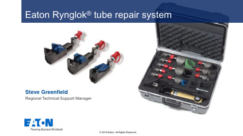
Eaton Rynglok tube repair system Steve GreenfieldAgenda•Metal/Metal swaged permanent repair - no elastomers - typical problems•Titanium repair fittings•Mates with multiple materials•Original design•Aftermarket•8000 psi limit•Titanium repair fittings•Mates with multiple materials•Similar design, weight optimized for OEM •Differentiated by color•Production and aftermarket•5000 psi limit•Over 1,000 tool kits in use•Used by most airlines, cargo & helicopter Operators •Military Aerospace, Land & Marine•Product launched in 1988•Well over 1,000,000 fittings in service•No reported failures•Fedex Memphis typically save $100K to 200K per useRepairs all tubes with few exceptions •Always refer to the AMM•Repair on wing rather than replace•Fully approved axial swage - not a radial swage •Compact tooling does not require 360 degrees access •Wide size range from 4 to 24 (1/4” to 1½” )•Repairs all damaged tubes for fluid* & pneumatic•Not used on landing gear or thrust reverser•Not used on potable waterPut fitting in tool Swage the fittingInspect finished swageHow to - repair in 6 simple steps Mark the tubeCheck the marksHow to- repair Fitting in useOnce rings areadvanced, aconstant loadis applied tomaintainswage•Simple-Reliable-Repeatable-Permanent. •Quick repairs, only requires 180 degree access •Long lasting tools, no assembly required •Low probability of incorrect swageCommercial OEM approvals•Airbus (all Including A350* A380*) 1997•Boeing (all except B787**) 1997•Lockheed (L1011) 1991•Cessna (Citation models) 1992•ATR 42/72 (all models) 2000•de Havilland (DASH 8) 1994•Embraer (all models) 2003•Bombardier CRJ 2004•* approved for repairs not SB implementation•** Imminent•Airbus Production & Repairs (A350 & A380)•Boeing Production & Repairs (B737, B747-8, B787)Solution kits and tooling options •Available in ranges specific to your needs up tofull & flyaway kits•Tooling for cutting and deburringInstalled repairTypical tube damageInstalled by OEM A380Video Presentation Live DemonstrationRynglok Information /Eaton/ProductsServices/Aerosp Array ace/LiteratureLibrary/index.htm?litlibtarget=979679288135TF100-1 Rynglok bulletin, R5 systemTF100-17 Rynglok bulletin, R8 systemTF100-75 R5 cross ref to AS standardsand fittingsTF100-20 R8 wall chart, configurationoptionsTF100-67 Installation guideDS100-53 Installation sequenceKits & Fittings Stocked by SatairQuestions/CommentsHerber Aircraft are official distributor for Military, General aviation, OtherOne more thing……Additive Manufactured Rynglok ® R5 Tool (5,000 psi)Highlights•Lower operator inventory costs.•Universal tools for all sizes – 3 less tools per kit (48% weight reduction per kit) •Updated geometry and removal of ball detents to increase tool lifeQualification and Reliability•Qualified to AS5959•Long Service life designed for OEM•Burst Pressure tested up to 20,750 psi for safetyTimeline•Size -16 to be introduced on 9/18 •Sizes -10 and -12 expected end of 2019Features & Benefit:•Designed for 5K Rynglok Lightweight Fittings•Tools designed to reduce total assembly time and fatigue •Requires only 180 degree access to complete fitting installation •Allows easy installation in limited space•Swivel quick connect hose fitting for increased maneuverabilityMaterial•Made from stainless steel 15-5 PH•Age hardened to increase strength and ductility/aerospace。
中国航行资料汇编
GEN 1.2ݴॢఖ֥ೆaݖބԛGEN 1.2 ENTRY, TRANSIT AND DEPARTUREOF AIRCRAFT1.ሹᄵ 1.General1.1外国民用航空器根据其国籍登记国政府与中华人民共和国政府签订的协定、协议的规定,或者经中国民用航空局批准或者接受,方可飞入、飞出中华人民共和国领空和在中华人民共和国境内飞行、降落。
1.1 A foreign civil aircraft may enter or leave the airspace of the People’s Republic of China, and operate or land in the territory of the People’s Republic of China only in accordance with the air transport agreement concluded between the Government of the People’s Republic of China and the government of the State in which the aircraft nationality is registered, or in accordance with the approval or clearance of the Civil Aviation Administration of China.1.2在中华人民共和国境内飞行的航空器,必须具有国籍标志和登记标志。
没有国籍标志和登记标志的航空器,禁止在中华人民共和国境内飞行。
1.2An aircraft operating in the territory of the People's Republic of China shall bear its nationality and registration marks. No aircraft without nationality and registration marks shall fly within the territory of the People's Republic of China.1.3外国民用航空器国籍登记国发给或者核准的民用航空器适航证书、机组人员合格证书和执照,中华人民共和国政府承认其有效;但是,发给或者核准此项证书或者执照的要求,应当等于或者高于国际民用航空组织制定的最低标准。
海伦工具22吨杠杆杆压力栅栏说明书

Visit our website at: Emailourtechnicalsupportat:********************************When unpacking, make sure that the product is intactand undamaged. If any parts are missing or broken,please call 1-888-866-5797 as soon as possible.. All rights reserved.Read this material before using this product.Failure to do so can result in serious injury.IMPORTANT SAFETY INFORMATION1. Study, understand, and follow all instructionsbefore operating this device.2. Do not exceed rated capacity.3. Use only on hard, level surfaces.4. Lifting device only. Immediately after lifting,support the vehicle with appropriate means.5. Do not move or dolly the vehicle while on the jack.6. Failure to heed these markings may result inpersonal injury and/or property damage.7. Lift only areas of the vehicle as specifiedby the vehicle manufacturer.8. No alterations shall be made to this product.9. Never work on, under or around a loadsupported only by this device.10. Do not adjust safety valve.11. Wear ANSI-approved safety goggles andheavy-duty work gloves during use.12. Keep clear of load while lifting and lowering.13. Lower load slowly.14. Apply parking brake and chocktires before lifting vehicle. 15. Lift vehicle only at manufacturerrecommended locations.16. Inspect before every use; do not useif parts are loose or damaged.17. Do not use for aircraft purposes.18. The warnings, precautions, and instructionsdiscussed in this manual cannot cover allpossible conditions and situations that may occur.The operator must understand that common sense and caution are factors, which cannot be built into this product, but must be supplied by the operator.19. WARNING: The brass components of this productcontain lead, a chemical known to the Stateof California to cause cancer and birth defectsor other reproductive harm. (California Health& Safety Code § 25249.5, et seq.)IMPORTANT! Before first use:Check hydraulic oil level and fill to 1/4″ belowthe fill port as needed as stated on page 5. Thoroughly test the Jack for proper operation.If it does not work properly, bleed air from its hydraulic system as stated on page 5.Air Sourcea. Never connect to an air source thatis capable of exceeding 200 psi.Over pressurizing the tool may causebursting, abnormal operation, breakageof the tool or serious injury to persons.Use only clean, dry, regulated compressed air at the rated pressure or within the rated pressure range as marked on the tool. Always verify prior to using thetool that the air source has been adjusted to the rated air pressure or within the rated air-pressure range.b. Never use oxygen, carbon dioxide, combustiblegases or any bottled gas as an air sourcefor the tool. Such gases are capable ofexplosion and serious injury to persons.Symbol DefinitionsSymbol Property or statementPSI Pounds per square inch of pressureCFM Cubic Feet per Minute flowSCFM Cubic Feet per Minute flowat standard conditionsNPT National pipe thread, taperedChart continued in next column.SAVE THESE INSTRUCTIONS.Read the ENTIRE IMPORTANT SAFETY INFORMATION section at the beginning of this document including all text under subheadings therein before set up or use of this product.Note: For additional information regarding the parts listed in the following pages, refer to the Assembly Diagram near the end of this manual.Note: This air tool may be shipped with a protective plug covering the air inlet. Remove this plug before set up.Assembly1. Attach Adapter Holder (40) to the Lower Handle (18)with two U-Bolts (39) and Nuts (23). Refer to Figure A.Saddle Adapters (41– 43)U-Bolts (39)Nuts (23)Adapter Holder (40)R-Pin (44)Lower Handle (18)Figure A2. Tighten Nuts to secure Adapter Holder to Handle.3. Put height adjustment Saddle Adapters (41– 43)into the Adapter Holder (40) and lock each with an R-Pin (44). Refer to Figure A.5. Put the Handle Assembly into Handle Socketand secure with Bolt (6). Refer to Figure B.Bolt (6)Handle AssemblyFigure BAir SupplyTO PREVENT SERIOUS INJURY FROM EXPLOSION:Use only clean, dry, regulated, compressed air to power this tool. Do not use oxygen,carbon dioxide, combustible gases, or any other bottled gas as a power source for this tool.1. Incorporate a filter, regulator with pressure gauge,oiler, in-line shutoff valve, and quick coupler forbest service, as shown on Figure C on page 6and Figure D on page 7. An in-line shutoffball valve is an important safety device because it controls the air supply even if the air hoseis ruptured. The shutoff valve should be aball valve because it can be closed quickly. Note: If an automatic oiler system is not used,add a few drops of Pneumatic Tool Oil tothe airline connection before operation.Add a few more drops after each hour of continual use.2. Attach an air hose to the compressor’s air outlet.Connect the air hose to the Jack’s Air Inlet.Other components, such as a connectorand quick coupler, will make operationmore efficient, but are not mandatory.Do not install a female quick coupler on the tool. Such a coupler contains an air valve that willallow the air tool to retain pressure and operate accidentally after the air supply is disconnected. Note: Air flow, and therefore tool performance, canbe hindered by undersized air supply components. The air hose must be long enough to reachthe work area with enough extra length toallow free movement while working.3. Turn the tool’s throttle or switch to the off position;refer to Operation section for description of controls.4. Close the in-line shutoff valve betweenthe compressor and the tool.5. Turn on the air compressor according tothe manufacturer’s directions and allow itto build up pressure until it cycles off.6. Adjust the air compressor’s output regulatorso that the air output is enough to properlypower the tool, but the output will not exceedthe tool’s maximum air pressure at any time.Adjust the pressure gradually, while checking theair output gauge to set the right pressure range. 7. Inspect the air connections for leaks.Repair any leaks found.8. If the tool will not be used at this time, turn offand detach the air supply, safely discharge anyresidual air pressure, and release the throttleand/or turn the switch to its off positionto prevent accidental operation.Note: Residual air pressure should not be present after the tool is disconnected from the air supply. However, it is a good safety measure to attempt to discharge the tool in a safe fashion after disconnecting to ensure that the tool is disconnected and unpowered.Bleeding InstructionsBefore each use or if Bottle Jack performance decreases,check for excessive air and proper hydraulic oil level in Bottle Jack. If Jack appears not to be working properly, it may be necessary to purge its hydraulic system of excessive air as follows:1. Turn Knob completely clockwise.2. Release the Air Lever Lock and depress the Air Levercompletely for a few seconds. Then turn the Knob1-1/2 turns counterclockwise, releasing pressure.3. Remove the Filler Plug (22a), and fill theReservoir (21a) with hydraulic oil (not included).4. Depress the Air Lever completely fora few seconds to purge air.5. Turn Knob clockwise until snug to hold pressure.6. Top off the reservoir with hydraulicoil. Then replace the Filler Plug. IMPORTANT: After bleeding the Bottle Jack, test the Jack for proper operation prior to its actual use. Note: To prevent damage to the Bottle Jack, checkfor excessive air and/or low hydraulic oil regularly.F i g u r e C : P o r t a b l e A i r S u p p l y S e t u pAD e s c r i p t i o nF u n c t i o nA A i r H o s e C o n n e c t s a i r t o t o o lB F i l t e r P r e v e n t s d i r t a n d c o n d e n s a t i o n f r o m d a m a g i n g t o o l o r w o r k p i e c eC R e g u l a t o r A d j u s t s a i r p r e s s u r e t o t o o lD L u b r i c a t o r (o p t i o n a l )F o r a i r t o o l l u b r i c a t i o nE C o u p l e r a n d P l u g P r o v i d e s q u i c k c o n n e c t i o n a n d r e l e a s eF L e a d e r H o s e (o p t i o n a l )I n c r e a s e s c o u p l e r l i f eG A i r C l e a n e r / D r y e r (o p t i o n a l )P r e v e n t s w a t e r v a p o r f r o m d a m a g i n g w o r k p i e c eH A i r A d j u s t i n g V a l v e (o p t i o n a l )F o r f i n e t u n i n g a i r f l o w a t t o o lF i g u r e D : S t a t i o n a r y A i r S u p p l y S e t u pD e s c r i p t i o nF u n c t i o nA V i b r a t i o n P a d s F o r n o i s e a n d v i b r a t i o n r e d u c t i o nB A n c h o r B o l t s S e c u r e s a i r c o m p r e s s o r i n p l a c eC B a l l V a l v e I s o l a t e s s e c t i o n s o f s y s t e m f o r m a i n t e n a n c eD I s o l a t i o n H o s e F o r v i b r a t i o n r e d u c t i o nE M a i n A i r L i n e - 3/4″ m i n i m u m r e c o m m e n d e d D i s t r i b u t e s a i r t o b r a n c h l i n e sF B a l l V a l v e T o d r a i n m o i s t u r e f r o m s y s t e mG B r a n c h A i r L i n e -1/2″ m i n i m u m r e c o m m e n d e d B r i n g s a i r t o p o i n t o f u s eH A i r H o s e C o n n e c t s a i r t o t o o lI F i l t e r P r e v e n t s d i r t a n d c o n d e n s a t i o n f r o m d a m a g i n g t o o l o r w o r k p i e c eJ R e g u l a t o r A d j u s t s a i r p r e s s u r e t o t o o lKL u b r i c a t o r (o p t i o n a l )F o r a i r t o o l l u b r i c a t i o n L C o u p l e r a n d P l u g P r o v i d e s q u i c k c o n n e c t i o n a n d r e l e a s eM L e a d e r H o s e (o p t i o n a l )I n c r e a s e s c o u p l e r l i f eN A i r C l e a n e r / D r y e r (o p t i o n a l )P r e v e n t s w a t e r v a p o r f r o m d a m a g i n g w o r k p i e c eO A i r A d j u s t i n g V a l v e (o p t i o n a l )F o r f i n e t u n i n g a i r f l o w a t t o o lRead the ENTIRE IMPORTANT SAFETY INFORMATION section at the beginning of this manualincluding all text under subheadings therein before set up or use of this product.Park vehicle on a flat, level, solid, surface safely away from oncoming traffic. Turn off the vehicle’s engine. Place the vehicle’s transmission in “PARK” (if automatic) or in its lowest gear (if manual).Set the vehicle’s emergency brake. Then, chock the wheels that are not being lifted.Raising a VehicleNote: Safety shutoff prevents liftingin excess of rated load.1. Pull Handle Lever to reposition handle as desired.2. Turn Knob completely clockwise to itslocked position. Then connect an air hose(not included) to the Air Inlet.3. Depress the Air Lever until the Saddle of the BottleJack has nearly reached the vehicle lifting point.Position the Jack at 90° to the vehicle’s lifting point to ensure the Bottle Jack’s Saddle and vehiclelifting point are in alignment. If not, remove andthen reposition the Bottle Jack before lifting.4. To lift the vehicle, continue to depress the Air Lever.Once the vehicle is lifted, place theAir Lever Lock in its locked position.5. Set properly-rated jack stands (not included) tothe same minimum practical height accordingto the manufacturer’s instructions, makingsure they lock securely into position.6. Position the jack stand saddles under the vehiclemanufacturer’s recommended support points. WARNING! Ensure that the vehicle supportpoints are fully seated in the saddles of bothjack stands. Use a matched pair of jack standsper vehicle to support one end only.7. Slowly turn the Knob counterclockwise toease the vehicle onto the jack stands. Lowering a Vehicle1. Remove all tools, old vehicle parts, etc.from under the vehicle.2. Turn Knob completely clockwise.3. Release the Air Lever Lock and depress theAir Lever to raise the vehicle slightly abovethe jack stand saddles. Carefully removethe jack stands from under the vehicle.4. Slowly turn Knob counterclockwise(not more than one full turn) to lower the vehicle. 5. To prevent accidents, lower the Jack completelyand disconnect its air supply after use. Clean, thenstore the Jack indoors out of children’s reach. KnobHandleLeverAir InletAir LeverAirLeverLockSaddleSaddleAdaptersFigure E: ControlsProcedures not specifically explained in this manual must be performed only by a qualified technician.TO PREVENT SERIOUS INJURY FROM TOOL FAILURE:Do not use damaged equipment. If abnormal noise or vibration occurs, have the problem corrected before further use.1. BEFORE EACH USE, inspect the generalcondition of the tool. Check for:• loose hardware or housing• misalignment or binding of moving parts • damaged air hose • cracked or broken parts • any other condition that may affect its safe operation.2. AFTER USE, clean external surfaces of the Jackwith a clean, moist cloth and a mild detergent. Do not use solvents.3. WHEN STORING, turn Release Valvecounterclockwise to its open position. Store the Jack and its accessories in a clean, dry, safe location out of reach of children and other unauthorized people.4. DAILY - Air Supply Maintenance:Every day, maintain the air supply according to the component manufacturers’ instructions. Drain the moisture filter regularly.Performing routine air supply maintenance will allow the tool to operate more safely and will also reduce wear on the tool.5. Periodically, check the condition of the hydraulic fluid.Change the hydraulic fluid as needed through the Fill Plug. Thoroughly bleed Jack after changing fluid.TroubleshootingTO PREVENT SERIOUS INJURY AND DEATH:Use caution when troubleshooting a malfunctioning jack. Stay well clear of the supported load.Completely resolve all problems before use. If the solutions presented in the Troubleshooting guide do not solve the problem, have a qualified technician inspect and repair the jack before use.After the jack is repaired : Test it carefully without a load by raising and lowering it fully, checking for proper operation, BEFORE RETURNING THE JACK TO OPERATION .DO NOT USE A DAMAGED OR MALFUNCTIONING JACK!POSSIBLE SYMPTOMSPROBABLE SOLUTION (Make certain that the jack is not supportinga load while attempting a solution.)Jack will not lift at its weight capacitySaddle lowers under loadPump stroke feels spongy Saddle will not lift all the way Handlemoves upwhen jack isunder loadOil leaking from filler plugX X Check that Release Valve is fully closed. Bleed air from the system.XXXValves may be blocked and may not close fully. To flush the valves:1. Lower the Saddle and securely close the Knob.2. Manually lift the Saddle several inches.3. Open the Knob and force the Saddle down as quickly as possible.X X XJack may be low on oil.Check the oil level and refill if needed.Jack may require bleeding - see instructions.XUnit may have too much hydraulic oil inside, check fluid level and adjust if needed.Part Description Qty 1Bolt10 2Bolt2 3Right Side Plate1 4Circlip2 5Wheel2 6Bolt5 7Adjustable Frame1 8Base Plate1 9Left Side Plate1 10Handle Socket1 11Washer1 12Screw1 13Nut1 14Connector1 15Tie Rod-11Part Description Qty16Tie Rod-2117Screw118Lower Handle119Screw220Handle Connector121Slotted Pin122R-Pin123Nut524Spring125Tie Rod-3126Screw227Pin128Handle Lever129Handle Sleeve230Pin1Part Description Qty31Knob132Upper Handle133Pump Assembly134Washer235Air Hose136Valve Body Assembly137Quick Coupler-Male138Plate139U-Bolt240Adapter Holder141Saddle Adapter A142Saddle Adapter B143Saddle Adapter C144R-Pin345Saddle Adapter D1Main Parts List and DiagramPage 11For technical questions, please call 1-888-866-5797.Item 6327332a30a29a28a 27a26a25a22a 21a 20a 24a23a 18a15a13a 19a 16a 10a13a13a35a 34a 33a14a 15a12a 11a1a9a 8a 7a 6a 5a 4a3a2a16a16a 16a17a31a31a31a 31aParts List and Diagram A - Hydraulic UnitPLEASE READ THE FOLLOWING CAREFULLYTHE MANUFACTURER AND/OR DISTRIBUTOR HAS PROVIDED THE PARTS LIST AND ASSEMBLY DIAGRAM IN THIS DOCUMENT AS A REFERENCE TOOL ONLY . NEITHER THE MANUFACTURER OR DISTRIBUTOR MAKES ANY REPRESENTATION OR WARRANTY OF ANY KIND TO THE BUYER THAT HE OR SHE IS QUALIFIED TO MAKE ANY REPAIRS TO THE PRODUCT, OR THAT HE OR SHE IS QUALIFIED TO REPLACE ANY PARTS OF THE PRODUCT. IN FACT, THE MANUFACTURER AND/OR DISTRIBUTOR EXPRESSLY STATES THAT ALL REPAIRS AND PARTS REPLACEMENTS SHOULD BE UNDERTAKEN BY CERTIFIED AND LICENSED TECHNICIANS, AND NOT BY THE BUYER. THE BUYER ASSUMES ALL RISK AND LIABILITY ARISING OUT OF HIS OR HER REPAIRS TO THE ORIGINAL PRODUCT OR REPLACEMENT PARTS THERETO, OR ARISING OUT OF HIS OR HER INSTALLATION OF REPLACEMENT PARTS THERETO.Record Serial Number Here:Note: If product has no serial number, record month and year of purchase instead.Note: Some parts are listed and shown for illustration purposes only, and are not available individually as replacement parts.Harbor Freight Tools Co. makes every effort to assure that its products meet high quality and durability standards, and warrants to the original purchaser that this product is free from defects in materials and workmanship for the period of 90 days from the date of purchase. This warranty does not apply to damage due directly or indirectly,to misuse, abuse, negligence or accidents, repairs or alterations outside our facilities, criminal activity, improper installation, normal wear and tear, or to lack of maintenance. We shall in no event be liable for death, injuriesto persons or property, or for incidental, contingent, special or consequential damages arising from the use ofour product. Some states do not allow the exclusion or limitation of incidental or consequential damages, so the above limitation of exclusion may not apply to you. THIS WARRANTY IS EXPRESSLY IN LIEU OF ALL OTHER WARRANTIES, EXPRESS OR IMPLIED, INCLUDING THE WARRANTIES OF MERCHANTABILITY AND FITNESS. To take advantage of this warranty, the product or part must be returned to us with transportation charges prepaid. Proof of purchase date and an explanation of the complaint must accompany the merchandise.If our inspection verifies the defect, we will either repair or replace the product at our election or we mayelect to refund the purchase price if we cannot readily and quickly provide you with a replacement. We willreturn repaired products at our expense, but if we determine there is no defect, or that the defect resultedfrom causes not within the scope of our warranty, then you must bear the cost of returning the product.This warranty gives you specific legal rights and you may also have other rights which vary from state to state.3491 Mission Oaks Blvd. • PO Box 6009 • Camarillo, CA 93011 • 1-888-866-5797。
缓勃茵斯大气航线虚拟运营手册说明书

BUFFALO AIRWAYS VIRTUAL Operations Manual Nov 2019Our HistoryBuffalo Airways Virtual was created in early 2010 by Thomas Emms & Randy Kearnes. Inspired by the television show Ice Pilots NWT and our love of vintage aircraft, we contacted Buffalo Airways for permission and a few days later, the good news arrived!After receiving permission from Buffalo Airways we decided to design a simple, unique website. We also decided to create our own version of the Buffalo Airways logo which can be seen on the header. Buffalo Airways Virtual is the Official VA of Buffalo Airways. This means that we are able to be in close contact with the staff at Buffalo Airways and they may join us from time to time on Teamspeak, the forums and in the air on VATSIM.All pilots joining Buffalo Airways have to complete at least 10 hours on Flight Simulation software. They are now required to fly those 10 hours with Buffalo Airways Virtual. Through our strong partnership with the “Real World Buffalo Airways” we will bring exciting features not currently provided by other Virtual Airlines. These will include features such as a direct link to the Buffalo Airways Satellite System, meaning we can view & track the Buffalo Airways aircraft in real time! We also provide a 10% discount code on all Buffalo Air Wear products.Buffalo Airways Virtual's official launch date was the 1st of August 2010 however we were accepting registrations before this. Pilots who registered before this date have been given a special "Founding Member" award. Our launch event was taking the CL‐215's from Red Deer, Over Canada then Onwards to Europe! Since allowing registrations, Buffalo Airways Virtual has been growing by leaps and bounds. We had over 50 pilots in less than 8 weeks! We also have a steady number of flights being flown each day!Membership Requirements & Application InformationTo join Buffalo Airways Virtual you must be at least 16 years old. This is to comply with the worldwide Children’s Online Privacy Protection Act (COPPA) of 1998. You must own a legal, working copy of Microsoft® Flight Simulator 2002, 2004 or Microsoft FlightSimulatorX. You must have a valid e‐ma il address. You also agree to file your first PIREP (Flight Report) within 14 days of your registration being accepted, you will be mature, not use any sort of bad language, racism or abusive comments. You will not submit any false information when submitting application(s) or representing Buffalo Airways Virtual in any way. You will allow Buffalo Airways Virtual to send you NOTAMS via E‐Mail (Max 3 per Week).I understand that my application can be rejected at the discretion of Buffalo Airways Virtual or Buffalo Airways Ltd without prejudice. There are no payments required to join Buffalo Airways Virtual and therefore no refund will be given.Please note there is a maximum of 2 accounts, If your 2nd account gets deleted any further applications will be rejected. If there are 2 further registrations, 4 in total, your IP and email may be blocked from our web server for spamming.Applications can be denied for any of the following reasons:Buffalo Airways Virtual Operations Manual•Full/Part of my real name is written in capital (CAPITAL) letters only.•Invalid Birth Date, eg; Under 16 YOA, Partial or No birth date given.•Invalid e‐mail account, eg; gives an error message.•False location given on application.•Any other valid reason given by staff.DownloadsBuffalo Airways Virtual has a variety of downloads available in the “Download Centre”. These include Scenery, Aircraft and Textures. There are freeware aircraft available and also a range of textures for Pay ware aircraft. Most downloads include instructions. Please note that we are not responsible for any 3rd party website links or downloads. All files are copyright to their original owners.Flight OperationsBuffalo Airways Virtual does not assign flights. You can view a full list of our flights on the‘Schedules’ page or the forum section, “Flight Schedules & Routes”. View Flights:/index.php/Schedules/viewAll of our flights are created to be as realistic as possible, most of the flight information is provided to us by Buffalo Airways flight crews.ACARS ProgramsFreeware ACARS Programs; SmartCars (preferred), BFL ACARS, XACARS & FSACARS, VATAWARE Flight Log.Payware ACARS Programs; FS Passengers, FS Flight Keeper, FSCaptain.All ACARS Configuration files can be found on your Profile Page.All Pireps must contain a flight log from one of the sources listed above.Jump seatingPilots are not required to fly from the last airport they landed at. You can fly any flight at any time as long as you have enough hours to fly the aircraft used for that flight.Inactive PolicyNew Pilots: After your registration is accepted, you must file one (1) PIREP within 14 days otherwise your account will be deleted.After First Flight: Pilots are required to file at least one PIREP every 30 days. If a PIREP is not filed within 30 days the pilot will be set to inactive. If after 90 days a PIREP has not been filed, the pilot will be deleted.If your account is set to inactive you can re‐activate yourself by filing a valid PIREP.Once an account has been deleted, you can re‐apply to join however there are no guarantees your 2nd application will be accepted. The hours, awards, and flights you had on your previous account will not be added to your new account, nor will you receive your previous pilot number.If you are unable to fulfil this commitment, please contact your hub manager to make an alternative arrangement.Leave Of Absence (LOA) If a Pilot wishes to take a Leave Of Absence of longer than 30 days you must contact your Hub Manager to ensure your account is not set to inactive or deleted.Hub Manager contact information can be found here:/index.php/pages/staffPIREPSTime AccelerationFlying greater than 1x speed is not allowed. Pilots who submit PIREPS with any speed greater than 1x will have their PIREP rejected.Pausing All PIREPs with pausing in them will be accepted, regardless for how long.AFK (Away From Keyboard) ChecksTotal AFK time must not exceed 60 minutes for any flight. AFK time in excess of 60 minutes on any individual Pirep will be rejected. Once an AFK is activated, pausing does not stop the AFK time. Please check your ACARS for an AFK prior to pausing for extended periods.Aircraft Flights must be flown using the correct aircraft. Flight flown with a different aircraft will be rejected.Slewing Flights using slew will be rejected, even if activated on the ground.Touchdown Rates The acceptable touchdown rate must be between -500 fpm and +50fpmAltitude/Flight Level Flights in the Electras and Orions must be flown between flight level 180 (18,000 feet) & flight level 240 (24,000 feet) unless otherwise indicated in the flight schedule.Fuel DataPIREPS may also be rejected if the fuel usage / flight data is wrong or there is none at all. There must also be no mid‐air refuelling. This is at the staff’s discretion.Manual PIREPSManual PIREPS are accepted at the Hub Manager’s discretion and are only to be used if an error with the Acars system is encountered during flight, all manual PIREPS must contain a flight a log.Multiplayer FlyingBuffalo Airways Virtual encourages pilots to use the Virtual Air Traffic SimulationNetwork™ (VATSIM™, https:///) or the International Virtual Aviation Organisation™ (IVAO™, https://www.ivao.aero/ ). Both networks offer worldwide Air Traffic Control (ATC) coverage and real time flying with fellow pilots. You can connect to such networks using either Squawk box or FSInn for Vatsim or IVAO’s own program, IVAP.Buffalo Airways Virtual also organizes “New Pilot Nights” on these networks, see forum for details.RanksUpon joining Buffalo Airways Virtual pilots are assigned the rank of “Ramp HandTransfer HoursBuffalo Airways Virtual does not transfer hours from any previous virtual airlines. The only person(s) allowed transfer hours is real world Buffalo staff who will be given 1 Transfer flight and 50 hours upon registration.ForumsBuffalo Airways Virtual has an active forum for Pilots only. We encourage each pilot to use the forum and maintain a regular presence. Once your application has been accepted your forum Username and Password will be created automatically within 48hrs and sent via email.DiscordBuffalo Airways Virtual has an active 24/7 Discord server setup for Pilots only.We encourage all pilots to use this server.You can find our AUP (Acceptable Usage Policy) Here:/files/BUFAUP.pdfOur Discord Information can be found under the “Resources” dropdown on our website.You can join us on Discord at any time here -https://discord.gg/9m47AYQContacting BFL VirtualBuffalo Airways Virtual’s main office(s) are based in Tyne & Wear, United Kingdom and Briti sh Columbia, Canada. If you are a Pilot, the best way to contact a member of staff is via the website PM System or the Forum PM System.If you wish to contact a member of staff directly, please use the website “Contact Us” form. | | | 。
IATA第50期危险品规则(2009)显著修订和变化
IATA第50期《危险品规则》(2009)显著修订和变化(注:中文仅为参考)1–Applicability 适用性1.2.3–Exceptions. The exception for aircraft used to transport dangerous goods to provide medical aid to a patient during flight has been clarified. The revised text makes it clear that the aircraft can be one adapted for specialized use, i.e. air ambulance, or may a regular public transport aircraft where the operator approves the carriage.1.2.3-例外。
为了在飞行中向病人提供医疗救援而携带危险品的航空器被明确为例外。
修改后的内容明确了此类航空器可以是那些为特殊用途改装的飞机,如飞行医院,或是经运营人同意承运的执行定期航班的公共运输飞机。
1.5–Training Requirements 训练要求1.5.0.3. There has been a change to the provisions on recurrent training. The recurrency period is still 24 months. However, there is now provision for a 3-month “window” that allows for recurrent training conducted within the final 3 months of the 24-month period to be considered to have been completed on the expiry date of the 24-month period. For example, a person who completed a course on 30 June 2007 needs to complete a revalidation by 30 June 2009. However, the revalidation may be taken between 1 April and 30 June 2009 for the revalidation to be considered to have been completed on 30 June 2009. The next revalidation date will then be 30 June 2011.1.5.0.3对复训的周期时间要求做补充说明。
接送飞机程序
质量体系 QUALITY SYSTEM - FP 1315-16主题SUBJECT 接送飞机程序Arrival and Departure Procedures修订REV 2 日期DATE 2009-08-25 页码PAGE1 12of职能部门 Functional Dept. 安全监督部Safety Supervision Department 部门审核人 Reviewed By相关部门 Dept.’s Affected 航线部,地面保障部,厂房设施部Line Maintenance, GSE, Facilities Department除非另有说明,本程序自批准之日起生效。
Except as otherwise stipulated, this FP comes into effective upon the date of approval.批准人 Approved By有效页清单 List of Effective Pages页码Page 修订Rev. 日期 Date 页码Page 修订Rev. 日期 Date 页码Page 修订Rev. 日期Date1 2 2009-08-25 2 2 2009-08-25 3 2 2009-08-25 4 2 2009-08-25 5 2 2009-08-25 6 2 2009-08-25 7 2 2009-08-25 8 2 2009-08-25 9 2 2009-08-25 10 2 2009-08-25 11 2 2009-08-25 12 2 2009-08-25目录 Table of Contents1.0 简介 Introduction2.0 接机程序 Arrival procedures3.0 送机程序 Departure procedures4.0 机组通告 Flight crew notification 附录1, 2, 3 & 4 Attachment 1, 2, 3 & 4质量体系 QUALITY SYSTEM - FP 1315-16主题SUBJECT 接送飞机程序Arrival and Departure Procedures修订REV 2 日期DATE 2009-08-25 页码PAGE 2 12of1.0 简介Introduction1.1 目的为机械员建立一个标准程序来规范接送飞机。
飞机每日维护工作单 - 机电 - 驾驶舱
Aircraft Effectivity飞机适用范围:
Check all the control levers and switches are in correct position.
检查各操作手柄及有关电门位置正确。
Check all the following checklists / onboard documents are in place : 检查下列各检查单/随机资料齐全完好在位:
FOR A/C B5046, B5047 :
对于飞机B5046、B5047:
737-300/500 Dispatch Deviations Guide (DDG)
737-300/500放行标准
机组氧气要求
对于容量为39立方英尺氧气瓶所需压力
氧气瓶温度
使用氧气的机组数量
对于容量为76立方英尺氧气瓶所需压力
氧气瓶温度使用氧气的机组数量
对于容量为114/115立方英尺氧气瓶所需压力氧气瓶温度使用氧气的机组数量
***END OF CARD***
Aircraft Effectivity飞机适用范围: Page页码。
Vertical Aerospace-Honeywell合作开拓无人驾驶小型飞机说明书
MICHAEL CERVENKA, CEO, VERTICAL AEROSPACE LTD. “Urban air mobility represents the biggest disruption aviation has seen since the dawn of the jet age in the 1960s. The combination of Honeywell’s compact fly-by-wire control systems and electrification is opening up a whole newopportunity for transportation.”Case StudyHoneywell’s flight systems are helping make urban air mobility (UAM) a reality.VERTICAL AEROSP ACE P ARTNERS WITH HONEYWELL TO TRANSFORM TRANSPORT A TIONOVERVIEWand carbon-free requires partners withthe know-how and can-do attitude torealize the future. Vertical Aerospacepartnered with Honeywell Aerospacefor its Compact Fly-By-Wire system,and its ability to achieve the standardsand safety integrity levels required tocertify aircraft for commercial use.Since its inception in 2016, VerticalAerospace has grown to more than110 world-class engineers andtechnical experts. The companywill fly its first passenger model in2021, and hopes to certify a vehicleby late 2023 or early 2024.BACKGROUNDEnergy entrepreneur Stephen Fitzpatrick got the idea for Vertical Aerospace when he was stuck in traffic one day. Thinking that there had to be a better way to get around, he decided to disrupt aviation by combining the pace and agility of auto racing with the rigor and safety-first culture of aerospace. Vertical Aerospace was born in2016, with the idea of producingfully-electric aircraft for urban environments to reduce ground congestion and create a foundationfor the decarbonization of aviation. “We want something that actuallycan make a real impact on society,”says Michael Cervenka, CEO atVertical Aerospace. “For me, [thatmeans] having a vehicle that is reallyeasy to fly and really easy to operate.”To remove responsibility from the pilot –and to ultimately create a completelyautonomous flying vehicle – companyexecutives knew they had to find a fly-by-wire system – a system that replacesmanual flight controls with an electronicinterface – that was lightweightand technologically advanced.“In the technology we’re developing,the pilot really isn’t flying the vehicle,”Cervenka says. “Instead, he’s tellinga series of computers what he wantsthe vehicle to do, where to go and whatto avoid. The computer actuallycontrols all of the different systemson the vehicle to make the pilot’sdirections happen reliably and safely.”Because fly-by-wire is a critical ingredientin the success of Vertical Aerospace’senterprise, company executivessearched far and wide to find the rightsystem. “We looked at all the differentpotential suppliers in the market,”recalls Cervenka. “We did extensive duediligence before selecting Honeywell.”3 | | To Transform Transportation Vertical Aerospace Partners with HoneywellTo Transform Transportation Vertical Aerospace Partners with Honeywell. | | 4SOLUTION“We were particularly impressed with the technology Honeywell already has, as well as the kind of forward thinking about how they’re going to upgrade and keep their products competitive,” Cervenka says. Vic Terry, Head of Digital Systems at Vertical Aerospace, says that seeing the pipeline of products to come from Honeywell Aerospace, not just in the fly-by-wire but also in adjacent products, was when Vertical Aerospace knew that Honeywell Aerospace was going to be a really good partner.Terry has also been impressed with the Honeywell Aerospace solution for being small enough to place around the aircraft very easily. “The fly-by-wire is the brains of the aircraft,” he says. “It’s a nontrivial task to integrate the components into the full system and make it work. Honeywell is working really closely with us and knocking down challenges as they come up.”The rapport between the two teams has opened up new opportunities beyond fly-by-wire.According to Terry, “We’ve moved into working with Honeywell on controllers because they bring some fantastic expertise there. We’re also looking at them for the wider avionics suite and our display systems, and I hope moving forward that Honeywell can bring some good technology to the autonomy piece as well.”Vertical Aerospace is also relying on Honeywell Aerospace for help meeting new eVTOL regulations established by the European Union Aviation Safety Agency (EASA). “The regulations set a really high bar at ten to the minus nine, which is what commercial transport currently works at,” Terry says. “I really believe that this is where we should be heading as an industry, so people can trust these aircraft to deliver them where they need to get to safely.”N61-2399-000-000 | 01/21© 2021 Honeywell International Inc.Honeywell Aerospace1944 E. Sky Harbor Circle Phoenix, AZ 85034BENEFITSKnowing that partnerships are critical to its success, the Vertical Aerospace team couldn’t be happier with itsHoneywell Aerospace relationship. “The things we looked for in a partner were the ability to hit aggressive weight, cost and safety targets,” Cervenka says. “Honeywell’s really stood out for me in hitting all of those criteria.” Cervenka says that Vertical Aerospace’s partnership with Honeywell Aerospace has been a key differentiator in terms of providing a rapid route to market at scale. “By bringing in the best possible technologies and the best minds,Honeywell gives us a real opportunity to significantly speed up the development cycle, de-risk the flight test program, and ultimately bring in things like F35 flight control technology to enable these vehicles to be really, really simple to fly.”With big dreams of transformingtransportation as we know it, Cervenka and his team know they’re getting closer to their goals with Honeywell Aerospace. He credits Honeywell Aerospace with giving Vertical Aerospace “a system that is significantly lighter and cheaper than you’d see on a conventional aircraft that will ultimately deliver the same levels of safety and reliability you’d expect on a big commercial vehicle.”。