一体式远程控制阀(模块)使用说明书20160525
阀门电动装置说明书

1.概述多回转阀门电动装置,简称为Z型电装,是阀门实现开启、关闭或调节控制的驱动设备。
Z型电装适用于闸阀、截止阀、隔膜阀、柱塞阀、节流阀、水闸门等。
可用于明杆阀,也可用于暗杆阀。
本系列电装具有功能全、性能可靠、控制系统先进、体积小、重量轻、使用维护方便等特点。
可对阀门实行远控、集控和自动控制。
广泛用于电力、冶金、石油、化工、造纸、污水处理等行业。
本产品的性能符合JB/T8528-1997《普通型阀门电动装置技术条件》的规定。
隔爆型的性能符合GB3836.1-2000《爆炸性气体环境用电气设备第1部分:通用要求》,GB3836.2-2000《爆炸性气体环境用电气设备第2部分:隔爆型“d”》及JB/T8529-1997《隔爆型阀门电动装置技术条件》的规定。
多回转电动装置按防护类型分:有户外型和隔爆型;按控制方式分:有常规型、整体型和整体调节型;按连接型式分:有转矩型、电站型和推力型。
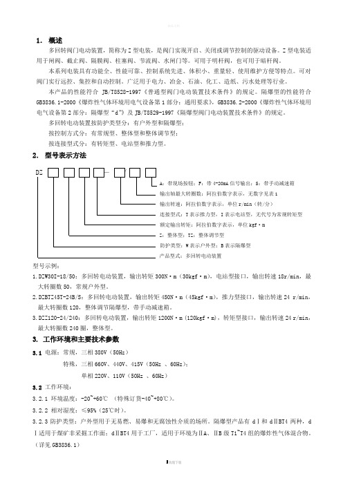
2.型号表示方法A:带现场按钮;F:带4-20mA信号输出;S:带手动减速箱输出轴最大转圈数:阿拉伯数字表示,无数字见表1输出转速:阿拉伯数字表示,单位r/min(转/分)连接型式:T表示推力型,I表示电站型,无代号为常规转矩型额定输出转矩:阿拉伯数字表示,单位kgf·mZ:整体型;TZ:整体调节型防护类型:W表示户外型;B表示隔爆型产品型式:多回转电动装置型号示例:1.DZW30I-18/50:多回转电动装置,输出转矩300N·m(30kgf·m),电站型接口,输出转速18r/min,最大转圈数50,常规户外型。
2.DZBTZ45T-24B/S:多回转电动装置,输出转矩450N·m(45kgf·m),推力型接口,输出转速24 r/min,最大转圈数120,整体调节隔爆型,带手动减速箱。
3.DZZ120-24/240:多回转电动装置,输出转矩1200N·m (120kgf·m),转矩型接口,输出转速24 r/min,最大转圈数240圈,整体型。
遥控阀操作说明

遥控阀操作注意事项
领料前需要确认:
先把转换手柄打至手动位置(如图所示手柄位置2),转动遥控阀手轮并观察蝶阀的阀门开度与限位指示器的显示是否一致。
如果不一致,现场调试,若未能解决则不领取该阀。
安装注意事项:
领取阀件后,应立即用纸胶带保护阀头管路接头,避免杂物进入控制管路造成封堵;用铝箔布包裹阀头(等同设备保护)。
在操作遥控阀前:
务必明确该阀所在系统和管路的位置,确认阀两端连接的舱柜和阀件是否满足开启条件。
如舱柜有人或处于封舱状态、前后其它阀件没有开启的情况,不可开启。
注意转换手柄位置,位置1为遥控模式,位置2为手动模式,是否满足当前操作需要。
为了规范使用遥控阀,无论任何时候,阀的开度需≥30°或完全闭合,以保证阀的可靠性及使用寿命!。
控制阀操作说明书(DOC)

MASONEILAN21000系列控制阀操作手册(中文版)二○○三年日本MASONEILAN 调节阀操作手册(中文1 目 录调节阀代码注释...............................................................2 1 引言..............................................................................3 2 概述..............................................................................3 3 拆除..............................................................................3 4 安装..............................................................................3 5 送气管道........................................................................4 6 阀体拆卸 (4)6.1 螺纹阀芯 (4)6.2 速换阀芯..................................................................5 7 维修/检修 (6)7.1 螺纹基座拆除 (6)7.2 套管拆除 (6)7.3 研磨基座 (6)7.3A 螺纹阀芯…………………………………………………7.3B 速换阀芯…………………………………………………7.4 逻辑双重端阀……………………………………………………7.5 阀芯轴插杆………………………………………………………7.6 包装箱(标准) ……………………………………………………7.7 包装箱(润滑) ……………………………………………………7.8 软基座活塞……………………………………………………… 8 阀体再组装……………………………………………………………8.1 螺纹微调…………………………………………………………8.2 速换微调………………………………………………………… 9 附图……………………………………………………………………日本MASONEILAN 调节阀操作手册(中文2 模型序号图1尺寸和比率图2日本MASONEILAN 调节阀操作手册(中文3 1 引言在安装、运行和维修该设备之前,应全面审查并理解下列指南。
CHPN-3控制模块使用说明书(最终版)

CHPN-3控制模块使⽤说明书(最终版)CHPN-3智能阀位控制器使⽤说明书使⽤控制器之前请仔细阅读说明书⼀、功能概述CHPN-3智能阀位控制器为柜装式控制仪表。
配合位移检测电位计使⽤,可控制电动或电液动执⾏机构动作,从⽽实现各类调节型阀门的开度⽆极调节。
置的模拟量输⼊/输出模块和数字通讯模块可与中控室连接,实现产品的⾃动化控制。
CHPN-3智能阀位控制器设有2个4位数显装置,可分别显⽰被控阀门的实际开度和设定开度;4个调节按键可任意设置阀门零点(全关位置)、满点(全开位置),并能现场修正部控制参数,以适应不同⽤户需求。
⼆、安装接线三、使⽤环境CHPN-3智能阀位控制器安装在电⽓控制箱,应在室环境使⽤。
使⽤环境要求说明如下:1、⼯作电压围:120VAC~260VAC 50/60Hz;2、使⽤温度围:-20℃~65℃;3、使⽤湿度围。
≤90%RH,不结露;4、周围不含强腐蚀性、易燃易爆⽓体或粉尘。
四、操作说明CHPN-3智能阀位控制器操作⾯板上设有2个4位数显装置、4个LED指⽰灯和4个操作按键(参见下图)。
⽤户可根据需要现场设置各位置点,并可即时修正相关控制参数。
置的EEPROM存储模块可永久记忆各重要数据。
参数说明:按住设定键进⼊部控制参数设定菜,利⽤增加/减少按键可调整参数容,⼀个参数设置完成后,按⼀下设定键可进⼊下个参数的设定状态。
可设置的参数见下表说明。
部参数涉及仪表的控制性能,以致影响整机的运注:在参数设定状态下,若连续5秒⽆按键操作便⾃动保存设置并退出设定状态!调试步骤说明:第⼀步位置定位调零调满第⼆步惯性与死区调整第三部输出电流调零调满(外部线接好,检查⽆误后⽅可通电)⼀、位置定位调零调满(初装阀门必须将传感器、阀门与仪表调定同⼀位置)1、点动按“SET”键,找到红⾊数码管显⽰“AH”参数,点按“▲”上键,把绿⾊数码管参数值调为“2”,再点动按下“SET”键,调到显⽰画⾯。
2、⼿动把阀门全关到位,按向“▼”下键5秒钟,当看到红⾊数码管红字闪动⼀下,即调零成功、红⾊数码管显⽰“000”。
模块控制器系列的远程I O数字模块说明书

GENERAL DESCRIPTIONThe Model CSDIO series modules are digital I/O modules designed for useSERIES DIGITAL MODULECUS LISTEDU LIND. CONT. EQ.GENERAL SPECIFICATIONS1. POWER: Derived from system backplane. (CSDIO draws 170 mA max. loadon power input of MASTER). Modules may be hot-swapped (replaced while powered up).2. LEDs:STS - Status LED shows module condition.IN1-IN8 - LEDs are lit when associated input is active.OP1-OP6 - LEDs are lit when associated output is active.ALM - Alarm LED is lit when an internal alarm condition exists.3. MEMORY: Non-volatile memory retains all programmable parameters.MASTER also stores the parameters in order to reprogram modules that are replaced.4. INPUTS: DIP switch selectable for sink or sourceMaximum voltage: +30 VDC, reverse polarity protectedOff V oltage: < 1.2 V oltsOn V oltage: > 3.8 V oltsInput Impedance: Source Mode 10K ohms; Sink Mode 20K ohmsInput Frequency*:Filter switch on: 50 HzFilter switch off: 300 Hz* Actual useable frequency limited by communication to external device.5. OUTPUTS: Outputs available as FORM-A relay or Solid State NFET.Form A Relay Output:Type: N.O.The following pairs of relays share the common terminal: 1&2, 3&4, 5&6 Current Rating by pair: 3 Amps @ 30 VDC / 125 V AC resistive1/10 HP @ 125 V ACLife Expectancy: 200,000 cycles at maximum load rating. (Decreasing load, increasing cycle time, and use of surge suppression such as RC snubbers increases life expectancy.)Solid State Output:Type: Switched DC, N Channel open drain MOSFETContact Rating: 1 ADC maxVDS ON: < 0.2 V @ 1 AVDS MAX: 30 VDCOffstate Leakage Current: 0.5 A max6. LOGIC (BOOLEAN) MODE:Count Frequency: 200 Hz/input when input is directly connected (soft-wired) to the counter.Logic Propagation Delay: 400 msecs. max.Timer Accuracy: 0.2%7. ISOLATION LEVEL: 500 Vrms @ 50/60 Hz for 1 minute between thefollowing:InputsOutputsCS Master Power Supply Input8. COMMUNICATIONS: Provided by the CS Master 9. ENVIRONMENTAL CONDITIONS:Operating Temperature Range: 0 to +50 °CStorage Temperature Range: -40 to +85 °COperating and Storage Humidity: 85% max relative humidity, non-condensing, from 0 to +50 °CVibration According to IEC 68-2-6: Operational 10 to 150 Hz, 0.075 mm amplitude in X, Y, Z direction 1 g.Shock According to IEC 68-2-27: Operational 25 g’s (10 g’s relay), 11 msec in 3 directions.Altitude: Up to 2000 meters10. CERTIFICATIONS AND COMPLIANCES:SAFETYUL Listed, File # E302106, UL508, CSA C22.2 No. 14-M05LISTED by Und. Lab. Inc. to U.S. and Canadian safety standards IEC 61010-1, EN 61010-1: Safety requirements for electrical equipment for measurement, control, and laboratory use, Part 1.ELECTROMAGNETIC COMPATIBILITYEmissions and Immunity to EN 61326: 2006: Electrical Equipment for Measurement, Control and Laboratory use.Notes:1. Criterion A: Normal operation within specified limits.2. Criterion B: Temporary loss of performance from which the unit self-recovers.3. Power supplied from back plane via Master Module.11. CONSTRUCTION: Case body is burgundy high impact plastic. For indooruse only. Installation Category II, Pollution Degree 2.12. CONNECTIONS: Removable wire clamp screw terminal blocks.Wire Gage: 28-16 AWG terminal gage wireTorque: 1.96-2.23 inch/lbs (0.22-0.25 N-m)13. MOUNTING: Snaps on to standard DIN style top hat (T) profile mountingrails according to EN50022 -35 x 7.5 and -35 x 15.14. WEIGHT: 6.6 oz (187.1 g)Electrostatic discharge EN 61000-4-2Criterion B4 kV contact discharge8 kV air discharge Electromagnetic RF fields EN 61000-4-3Criterion A10 V/mFast transients (burst)EN 61000-4-4Criterion Bpower 2 kVI/O signal2 kV1 kVSurge EN 61000-4-5Criterion Bsignalpower1 kV1 kV L-L,2 kV L-GRF conducted interference EN 61000-4-6Criterion A3 V/rmsEmissions:Emissions EN 55011Class AI/O signal connectected to powerImmunity to Industrial Locations:EMC INSTALLATION GUIDELINESAlthough Red Lion Controls Products are designed with a high degree of immunity to Electromagnetic Interference (EMI), proper installation and wiring methods must be followed to ensure compatibility in each application. The type of the electrical noise, source or coupling method into a unit may be different for various installations. Cable length, routing, and shield termination are very important and can mean the difference between a successful or troublesome installation. Listed are some EMI guidelines for a successful installation in an industrial environment.1. A unit should be mounted in a metal enclosure, which is properly connectedto protective earth.a. The mounting clip that connects to the DIN rail should have the DIN railconnected to protective earth.2. Use shielded (screened) cables for all Signal and Control inputs. The shield(screen) pigtail connection should be made as short as possible. The connection point for the shield depends somewhat upon the application.Listed below are the recommended methods of connecting the shield, in order of their effectiveness.a. Connect the shield to earth ground (protective earth) at one end where theunit is mounted.b. Connect the shield to earth ground at both ends of the cable, usually whenthe noise source frequency is over 1 MHz.c. Connect the shield to common of the module and leave the other end of theshield unconnected and insulated from earth ground.3. Never run Signal or Control cables in the same conduit or raceway with ACpower lines, conductors, feeding motors, solenoids, SCR controls, and heaters, etc. The cables should be run through metal conduit that is properly grounded. This is especially useful in applications where cable runs are long and portable two-way radios are used in close proximity or if the installation is near a commercial radio transmitter. Also, Signal or Control cables within an enclosure should be routed as far away as possible from contactors, control relays, transformers, and other noisy components.4. Long cable runs are more susceptible to EMI pickup than short cable runs.Therefore, keep cable runs as short as possible.5. In extremely high EMI environments, the use of external EMI suppressiondevices such as Ferrite Suppression Cores for signal and control cables is effective. The following EMI suppression devices (or equivalent) are recommended:Fair-Rite part number 0443167251 (RLC part number FCOR0000)TDK part number ZCAT3035-1330ASteward part number 28B2029-0A06. To protect relay contacts that control inductive loads and to minimize radiatedand conducted noise (EMI), some type of contact protection network is normally installed across the load, the contacts or both. The most effective location is across the load.a. Using a snubber, which is a resistor-capacitor (RC) network or metal oxidevaristor (MOV) across an AC inductive load is very effective at reducing EMI and increasing relay contact life.b. If a DC inductive load (such as a DC relay coil) is controlled by a transistorswitch, care must be taken not to exceed the breakdown voltage of the transistor when the load is switched. One of the most effective ways is to place a diode across the inductive load. Most RLC products with solid state outputs have internal zener diode protection. However external diode protection at the load is always a good design practice to limit EMI.Although the use of a snubber or varistor could be used.RLC part numbers: Snubber SNUB0000Varistor ILS11500 or ILS23000Note: Reference manufacturer's instructions when installing any EMI suppression device.7. Also, care should be taken when connecting input and output devices to theinstrument. When a separate input and output common is provided, they should not be mixed. Therefore a sensor common should NOT be connected to an output common. This would cause EMI on the sensitive input common, which could effect the instrument’s operation.Visit RLC’s web site at for more information on EMI guidelines, Safety and CE issues as they relate to Red Lion Controls products.WIRINGWIRING CONNECTIONSAll conductors should meet voltage and current ratings for each terminal. Also, cabling should conform to appropriate standards of good installation, local codes and regulations. When wiring the module, use the numbers on the label to identify the position number with the proper function. Strip the wire, leaving approximately 1/4" (6 mm) of bare wire exposed. Insert the wire into the terminal, and tighten.HARDWARE INSTALLATIONATTACH MODULE TO BASESEPARATE BASE FROM MODULESolid State NFET VersionRelay Version Sourcing Input Sinking InputLEDSSTS – STATUS LEDThe Status LED is a dual color LED that provides information regarding the state of the module. This includes indication of the various stages of the start-up routine (power-up), as well as any errors that may occur.Startup RoutineError States ALM – ALARM LEDThe Alarm LED indicates the presence of a fault condition. FIRMWARE UPGRADEThe module’s firmware is stored in flash memory so that software/hardware conflicts are avoided, and so that software features may be added in the future.During a download, Crimson compares its own library of firmware files with those stored in the Master module. If they do not match, Crimson will download the necessary files. The Master then checks to make sure that the I/O modules contain the same firmware. If they contain a different revision, the Master will automatically copy those files into the module's flash memory. During this process, the module LEDs will flash rapidly, starting with the top row, and progressing through the remaining rows until the process is complete. CONFIGURATIONProgramming is done via Crimson, a Windows® compatible configuration interface. Please see the Crimson manual for more information.Red Lion Controls Headquarters20 Willow Springs Circle York PA 17406Red Lion ControlsChinaUnit 101, XinAn PlazaBuilding 13, No.99 Tianzhou RoadShangHai, P.R. China 200223 Red Lion ControlsEuropePrinterweg 10NL - 3821 AD AmersfoortRed Lion ControlsIndia54, Vishvas TenementGST Road, New Ranip, Ahmedabad-382480 Gujarat, India。
雨鸟电动远程控制阀(EFB-CP系列)--说明书

Electric remote control valves don’t come any better than EFB-CP Series valves, which are reclaimed ready in order to handle the harsh conditions in non-potable water situations. Need a contamination-proof, self-flushing screen that cleans itself and resists debris build-up in dirty water? The EFB-CP’s the one! Rain Bird brass valves offer long lifeand superior performance in high pressure applications.Features• Diaphragm made of chlorine and chemical-resistant materials in order to handle the harsh conditions of non-potable water • Red brass body and bonnet for longer life and more rugged performance at 200 psi (13.80 bar)• Reverse flow feature ensures valve will fail in the closed position if a tear or rip in the diaphragm occurs. Prevents flooding, water waste and landscape damage• Fluid resistor slows flow through the solenoid, reducing closing speed and preventing water hammer and system damage• One-piece solenoid design with captured plunger and spring prevents loss of parts.• Low power requirement allows for longer wire runs without increased wire gauge size • Manual internal and external bleed.• Adjustable flow control• Contamination-proof self-flushing filter screen resists debris build-up. Water flow continuously flushes the screen, dislodging particles and debris before they can accumulate and clog the filter Options (order separately)• Accommodates optional, field installed PRS-D pressure regulating module• Accepts latching solenoid for use with Rain Bird battery-operated controllers up to 150 psi (10.35 bar)• Compatible with ESP-LXD decoders Operating Range• Pressure: 15 to 200 psi (1.04 to 13.80 bar)• Flow with/without PRS-D: 5 to 200 gpm (1.14 to 45.40 m3/h; 19.2 to 757 l/m)• Temperature: up to 150° F (66° C)Electrical Specifications• Power: 24 VAC 50/60 Hz (cycles/sec) solenoid• Inrush current: 0.41 A (9.84 VA) at 60 Hz • Holding current: 0.14A (3.43VA) at 60Hz Models• 100EFB-CP: 1” (26/34)*• 150EFB-CP: 11⁄2” (40/49)*• 200EFB-CP: 2” (50/60)** BSP threads available; specify when ordering.Tech SpecEFB-CP Series ValvesClassic Hardware. Classic Performance.® Registered Trademark of Rain Bird Corporation© 2018 Rain Bird Corporation 6/18Rain Bird Corporation 6991 E. Southpoint Road Tucson, AZ 85756Phone: (520) 741-6100Fax: (520) 741-6522Rain Bird Technical Services (800) RAINBIRD (1-800-724-6247) (U.S. and Canada)Rain Bird Corporation970 West Sierra Madre Avenue Azusa, CA 91702Phone: (626) 812-3400Fax: (626) 812-3411Specification Hotline800-458-3005 (U.S. and Canada)Rain Bird International, Inc.1000 West Sierra Madre Ave.Azusa, CA 91702Phone: (626) 963-9311Fax: (626) 852-7343 The Intelligent Use of Water ™The electric remote control valve shall be a normally closed 24 VAC 50/60 Hz (cycles/sec) solenoid actuated globe pattern with a bal-anced pressure diaphragm design. The valve pressure rating shall not be less than 200 psi (13.80 bar). The valve shall have the following characteristics (circle one):Flow rate: ________ gpm m 3/h l/m Pressure loss not to exceed: _______ psi bar The valve body and bonnet shall be con-structed of heavy cast red brass; diaphragm shall be of EPDM rubber. All other internal parts shall be made of bronze, brass, and stainless steel to ensure corrosion resistance.The valve shall have both internal andexternal manual open/close control (internal and external bleed) for manually opening and closing the valve without electrically energizing the solenoid. The valve shall have internal manual bleed to prevent flooding of the valve box.The valve shall house a fully-encapsulated, one-piece solenoid. The solenoid shall have a captured plunger with a removable retainer for easy servicing and a leverage handle for easy turning. This 24 VAC 50/60 Hz solenoid shall open with 19.6 VAC minimum at 200 psi (13.80 bar). At 24 VAC, average inrush current shall not exceed 0.41 amps. Average holding current shall not exceed 0.28 amps.The valve shall have a stainless steel flow control stem with cross handle for regulating or shutting off the flow of water. The valve must open or close in less than one minute at 200 psi (13.80 bar), and less than 30 seconds at 20 psi (1.38 bar).The valve construction shall be such as to provide for all internal parts to be removable from the top of the valve without disturbing the valve installation.The valve shall have a contamination proof (CP) self-flushing stainless steel screenlocated at the valve inlet to filter out grit and prevent clogging of hydraulic control ports and assure reliable operation.Optional Feature SpecificationWhen so indicated on the design, the 1”, 11⁄2”, and 2” electric remote control valves shall have a pressure regulating module (PRS-D) capable of regulating outlet pressure be-tween 15 and 100 psi (±3 psi) (1.04 and 6.90 bar (±0.21 bar)).The PRS-D module shall have an adjusting knob for setting pressure and Schrader valve connection for monitoring pressure. Pressure shall be adjustable from the PRS-D when the valve is internally manually bled or electrically activated.SpecificationsBrass Electric Remote ControlEFB-CP ValveD38949HEO。
阀门定位器.模块使用说明书

阀门定位器.模块使用说明书ZXQ 系列电动阀门智能定位器/阀门操作器(电子式伺服控制器)使用说明书DOC NO :201109ZXQ20 ZXQ20ZXQ20ZXQ20目录1一、概述 (2)二、主要技术指标 (2)三、定位器面板 (3)四、接线方式 (5)五、设定操作方法 (6)六、错误代码列表 (9)附录:其它标定操作(出厂后如需此项操作,请在厂家指导下使用) (9)如顾客所购买的是本公司Z型(机电一体)执行器,内部定位器无需对执行器转角标定,接线无误即可正常使用。
系列电动阀门智能定位器是以工业单片机为核心的智能信号采集控制系统,体积小巧,可选择安装在电动执行器的接线盒内或以DIN导轨方式固定在外,能直接接收工业仪表或计算机等输出的4~20mA DC信号(其它输入信号类型可在出厂前定制),与电位器反馈的电动执行器配套对各种阀门或装置进行精确定位操作,能对电动执行器的转角(或位移)进行自由标定,同时输出4~20mA DC的执行器转角位置(或位移)反馈转换信号,可精确设定执行器转角位置的下限限位值和上限限位值,定位器采用3个按键操作,9个LED灯可直接显示定位器模态,4位数码LED通过2按键切换显示阀位实际开度值、阀位设定开度值、定位器壳内温度,操作方便。
通过U4参数可调) ●可接电动执行器反馈信号:电位器500Ω~10KΩ●可接收外部控制信号(DC):4~20mA (1~5V、0~10V、开关量等出厂前定制)●输入阻抗:250Ω;●通过修改U1参数可设定:①DRTA/正动作,RVSA/逆动作模态②输入信号中断时“中断”模态—OPEN(开)、STOP(停)、SHUT(闭)●可选:可控硅输出(AC,1000V,25A)●输出执行器位置信号:低漂移输出4~20mADC对应执行器全闭至全开,信号完全与输入隔离(光电隔离),输出负载≤500Ω●环境温度:0~80℃,相对湿度:≤90%RH ●有超温保护功能: 定位器壳内温度≥70℃时,定位器停止对执行器的开闭控制●外形尺寸:ZXQ2003→77mm(底面长)×76mm(底面宽)×51mm(高/厚);ZXQ2004→74 mm(底面长)×57mm(底面宽)×45mm(高/厚)ZXQ2004B→119mm(底面长)×76mm(底面宽)×26mm(高/厚)ZXQ2004C→62mm(底面长)×48mm(底面宽)×26mm(高/厚)●可通过按键自由标定输入信号所对应执行器的动作区间(一般标定为电动执行器全闭、全开位置)●可设定最大阀位限制值与最小阀位限制值●密码锁,防止误操作●防执行器频繁启动功能●带故障报警代码指示功能(E-0X)3按输入信号和执行器转角位置进行智能步距调整精确定位■1■5■壳上的接线图连接好电动执行器和电源连线,注意连接时的极性,为减少电机干扰,应将电动执行器的电机控制线和反馈信号线分开走线;定位器的弱电信号线应尽量短些,若必须使用较长的连线时,应采用屏蔽信号线,外屏蔽与控制柜外壳妥善接地。
控制器的远程调试说明书

控制器的远程调试说明书一、概述控制器的远程调试是一种便捷的远程调试工具,它可以通过网络连接到控制器,并提供一系列功能来帮助用户进行远程调试操作。
本说明书将详细介绍使用控制器的远程调试的方法和步骤,帮助用户快速上手并顺利进行远程调试。
二、系统需求在使用控制器的远程调试之前,请确保您的系统满足以下要求:1. 拥有可靠的网络连接;2. 与控制器处于同一网络环境中;3. 安装了支持远程调试的控制器管理软件。
三、连接控制器1. 打开控制器管理软件,并登录您的账户。
2. 在软件界面上找到远程调试功能入口,点击进入。
3. 在远程调试界面上,输入控制器的IP地址或域名,点击连接按钮。
4. 等待控制器与软件成功建立连接,连接成功后即可开始远程调试操作。
四、远程调试操作通过控制器的远程调试功能,您可以进行以下操作:1. 远程查看控制器状态:通过界面上提供的状态查看功能,可以实时了解控制器的运行状态,包括各个参数的数值、开关状态等。
您可以通过这些信息来判断控制器是否正常工作。
2. 远程修改参数设置:在远程调试界面上,您可以修改控制器的参数设置,包括工作模式、输出功率、阈值等。
修改参数后,控制器将立即生效。
3. 远程执行操作命令:通过远程调试界面上提供的操作命令按钮,您可以远程执行控制器的操作命令,例如启动、停止、重启等。
这些操作将直接在控制器上执行,并及时反馈结果。
4. 远程导出日志信息:如果您需要查看控制器的日志信息,可以在远程调试界面上导出日志文件。
导出的文件可以保存到本地进行进一步的分析和处理。
五、注意事项1. 在进行远程调试操作之前,请确保网络连接稳定,避免因网络问题导致连接中断或操作失败。
2. 远程调试功能仅适用于控制器管理软件中支持的控制器型号,请确认您的控制器型号是否支持远程调试功能。
3. 远程调试涉及到对控制器的实时监控和控制,请谨慎操作,避免误操作引起不必要的问题。
六、总结通过本说明书,您已经了解了控制器的远程调试方法和步骤。
- 1、下载文档前请自行甄别文档内容的完整性,平台不提供额外的编辑、内容补充、找答案等附加服务。
- 2、"仅部分预览"的文档,不可在线预览部分如存在完整性等问题,可反馈申请退款(可完整预览的文档不适用该条件!)。
- 3、如文档侵犯您的权益,请联系客服反馈,我们会尽快为您处理(人工客服工作时间:9:00-18:30)。
HW/JS.07-2016 一体式远程控制阀(模块) 使用说明书
安徽汉威电子有限公司 本说明书适用于F01-M/24V、F01-RS/24V、F02-M/24V、F03-M/24V、F03-RS/24V、FW01-M/24V、FW01-RS/24V、FW02-M/24V、FW03-M/24V、FW03-RS/24V型产品。 目录 1、产品简介 ........................................................................................................................................................ 1 2、技术参数 ........................................................................................................................................................ 1 3、功能特点 ........................................................................................................................................................ 1 4、外观与接口 .................................................................................................................................................... 2 4.1 一体式远程控制阀外观............................................................................................................................ 2 4.2 接口类型: ............................................................................................................................................... 2 4.3 电源接口 ................................................................................................................................................... 3 4.4 电机控制接口 ........................................................................................................................................... 3 4.5 M-BUS通讯接口 ........................................................................................................................................ 3 4.6 RS485接口定义.......................................................................................................................................... 3 5、状态指示 ........................................................................................................................................................ 4 6、应用方案 ........................................................................................................................................................ 4 6.1 热量表法 ................................................................................................................................................... 4 6.2 通断时间面积法和温度面积法 ................................................................................................................ 5 6.3 温控一体化 ............................................................................................................................................... 7 7、注意事项 ........................................................................................................................................................ 8 1
1、产品简介 阀控模块是阀门控制器的核心部件,通过接收室温控制器及远程终端的控制指令,实现对阀门的控制和开阀时间的统计。产品广泛应用于冷热水流体的通断控制,适用于工业、商业及家庭居室等温度控制,也可拓展应用于类似的系统中。 由阀控模块和执行器组成的阀门控制器与室温控制器、采集计算器、楼栋热量表可构成完善的热计量及分摊系统,实现温度智能控制、无线抄表的功能,并可达到节能减排的目的。 我公司研发生产的阀控模块电路由AC/DC电源、单片机控制电路、阀门驱动电路、状态指示电路、470无线模块构成,根据用户需求采用M-BUS或RS485通讯方式实现远程抄表功能。 模块驱动能力强、抗干扰性能好,工作稳定可靠,易于安装使用,得到广大热计量生产厂商的认可。
2、功能特点 2.1 记录开阀时间、累计工作时间、分摊热量等数据并上传; 2.2 可远程控制阀门开/关,设置温度、温控模式 2.3 可作为路由节点,将相邻节点数据转发至采集计算器,实现远距离通讯 2.4 阀门控制周期可设; 2.5 检测阀门开关状态功能; 2.6 断电自动开阀(可选关阀); 2.7 断电记忆功能; 2.8 可应用于热量表法、通断时间面积法、温度面积法和温控一体化。
3、技术参数 3.1 工作电压:12~24VDC或18~20VAC(推荐24VDC); 3.2 静态电流3mA; 3.3 电机驱动电压:3~5V(可定制); 3.4 电机驱动电流:1.5A; 3.5 开关动作时间:20s(可定制); 3.6 通讯方式:M-BUS(RS485可选)上行,470MHz无线射频(上/下行); 2
3.7 无线通信距离:空旷条件500米; 3.8 显示方式:LED指示(LCD可选); 3.9 工作环境湿度:≤95%RH。
4、外观与接口 4.1 一体式远程控制阀外观
图1:正面 图2:侧面 4.2 接口类型:本产品有M-BUS和RS485两种接口可选,具体板型如下图所示。
图3 M-BUS接口 3
图4 485接口 4.3 电源接口:输入12~24VDC或18~20VAC,不区分正负极,推荐使用24VDC。 4.4 电机控制接口: 1-公共端/COM(接地); 2-电机输出端B; 3-电机输出端A; 4-开阀限位开关; 5-关阀限位开关。 电机控制接口与阀门执行器连接,执行开阀操作时,A端输出为“+”,B端为“-”;执行关阀操作时,A端输出为“-”,B端为“+”。(限位开关为常开型) 4.5 M-BUS通讯接口:接M-BUS总线,不区分正负极。 4.6 RS485接口定义: 1-连RS485通讯线A; 2-连RS485通讯线B; 3-RS485备用输出电源地(根据需要连接); 4-RS485备用输出电源正极(根据需要连接)。 4
5、状态指示 图5 状态指示灯 指示灯1:开阀指示灯,开阀动作时闪烁,阀门开启后常亮。
指示灯2:关阀指示灯,关阀动作时闪烁,阀门关闭后常亮。 指示灯3:电源状态/通讯指示灯,电源接通后指示灯常亮,通讯时闪烁。
6、应用方案 按照上行通讯方式的不同可分为:M-BUS远传阀、RS485远传阀、无线一体阀;按照实现的方案可分为:远程控制阀、通断时间面积法、温度面积法和热量表温控一体化。 6.1热量表+远程控制阀 设备组成:数据采集器、热量表、一体式远程控制阀 实现原理:数据采集器通过M-BUS/RS485采集用户热量表和栋表的数据,上位机系统可通过GPRS数据采集器远程控制阀门,管理部门可根据用户实际缴费情况强制开关。
