Interface传感器
一种基本IEEE802.15.4无线智能化传感器网络实现探讨.
摘要:介绍了IEEE802.15.4协议的特点、构件及体系结构、发展前景,分析了IEEE1451智能传感器模型,提出了一种基于IEEE802.15.4协议的无线智能传感器网络结构设计,并探讨了其实现。
关键词:IEEE802.15.4 IEEE1451 智能传感器网络近年来,随着计算机技术、网络技术与无线通信技术的高速发展和广泛应用,人们开始将无线网络技术与传感器技术相结合,提供了无线网络化传感器的概念。
它不仅可以应用于Internet接入互连,还适用于有线接入方式所不能胜任的场合,以提供优质的数据传输服务。
例如,在工厂巨大的设备间、低速长距离的通信要求和危险的工业环境。
2000年12月IEEE 成立了IEEE802.15.4工作组,致力于定义一种从廉价的固定、便携或移动设备使用的极低复杂度、成本和功耗的低速率无线连接技术。
产品的方便灵活、易于连接、实用可靠及可继续延续是市场的驱动力。
一般认为短距离的无线低功率通信技术最适合传感器网络使用,传感器网络是802.15.4标准的主要布场对象。
将传感器与802.15.4设备组合,进行数据收集、处理和分析,即可决定是否需要或何时需要用户操作。
满足802.15.4标准的无线发射/接收机及网络被Motorola、Philips、Eaton、Invensys和Honeywell这些国际通信与工业控制界巨头们极力推崇。
目前,IEEE1451工作组已考虑在其基础上实现无线智能传感器网络WSN(Wireless Sensor Networks)。
本文探讨了基于IEEE802.15.4标准的无线智能传感器网络的实现。
1 基于IEEE802.15.4标准的智能传感器模型1.1 IEEE1451智能传感器模型智能传感器建立了一个标准化的传感器网络协议。
它规定了传感器模块的电子数据表单,也定义了访问数据表单、读取传感器数据、设置参数的数字接口。
IEEE1451的目的就是提供一个工业标准接口,有效地连接传感器和微控制器,并把传感器接入网络。
FlexiForce标准型号A201传感器说明书

DS Rev I 062821ISO 9001:2008 Compliant & 13485:2016 RegisteredThe FlexiForce A201 is our standard sensor and meets the requirements of most customers. The A201 is a thin and flexible piezoresistive force sensor that is available off-the-shelf in a variety of lengths for easy proof of concept. These ultra-thin sensors are ideal for non-intrusive force and pressure measurement in a variety of applications. The A201 can be used with our test & measurement, prototyping, and embedding electronics, including the FlexiForce Sensor Characterization Kit, FlexiForcePrototyping Kit, FlexiForce Quickstart Board, and the ELF™ System*. You can also use your own electronics, or multimeter.FlexiForce™Standard Model A201BenefitsPhysical PropertiesThickness 0.203 mm (0.008 in.)Length 191 mm (7.5 in.)** (optional trimmed lengths: 152 mm (6 in.), 102 mm (4 in.), 51 mm (2 in.))Width14 mm (0.55 in.)Sensing Area 9.53 mm (0.375 in.) diameterConnector3-pin Male Square Pin (center pin is inactive)Substrate Polyester Pin Spacing 2.54 mm (0.1 in.)✓ROHS COMPLIANT• Thin and flexible • E asy to use• C onvenient and affordable* Sensor will require an adapter/extender to connect to the ELF System. Contact yourTekscan representative for assistance.** Length does not include pins. Please add approximately 6 mm (0.25 in.) for pin length for a total length of approximately 197 mm (7.75 in).Typical PerformanceEvaluation ConditionsLinearity (Error)< ±3% of full scaleLine drawn from 0 to 50% loadRepeatability < ±2.5%Conditioned sensor, 80% of full force applied Hysteresis < 4.5% of full scaleConditioned sensor, 80% of full force appliedDrift< 5% per logarithmic time scaleConstant load of 111 N (25 lb)Response Time < 5µsecImpact load, output recorded on oscilloscope Operating Temperature -40°C - 60°C (-40°F - 140°F)Convection and conduction heat sources Durability≥ 3 million actuations Perpendicular load, room temperature, 22 N (5 lb)Temperature Sensitivity0.36%/°C (± 0.2%/°F)Conductive heating***All data above was collected utilizing an Op Amp Circuit (shown on the next page). If your application cannot allow an Op Amp Circuit, visit/flexiforce-integration-guides, or contact a FlexiForce Applications Engineer.***©Tekscan Inc., 2021. All rights reserved. Tekscan, the Tekscan logo, and FlexiForce are trademarks or registered trademarks of Tekscan, Inc.+1.617.464.4283|1.800.248.3669|****************|/flexiforceP urchase T oday o nline aT www .Tekscan .com /sToreVOLUMEDISCOUNTSA s k U sAb o u t Ou rSensing Area14 mm (.55 in.)191 mm (7.5 in.)6 mm (.25 in.)Actual size of sensorTrim LinesV OUT = -V REF * (R F / R S )• Polarity of V REF must be opposite the polarity of V SUPPLY • Sensor Resistance R S at no load is typically >1MΩ• Max recommended current is 2.5mAV OUTC 1R F V SS = GroundV DD = V SUPPLYC 1 = 47 pFR FEEDBACK (R F ) = 100kΩ POTENTIOMETER V REF OptionsSquare Wave Up to 5V , 50% Max Duty CycleDC0.25V - 1.25VMCP6004-V REF100K potentiometer and 47 pF are general recommendations; your specific sensor may be best suited with a different potentiometer andcapacitor. Testing should be performed to determine this.R SRecommended Circuit†This sensor can measure up to 4,448 N (1,000 lb). In order to measure higher forces, apply a lower drive voltage (-0.5 V, -0.25 V, etc.) and reduce the resistance of the feedback resistor (1kΩ min.). To measure lower forces, apply a higher drive voltage and increase the resistance of the feedback resistor.Sensor output is a function of many variables, including interface materials.Therefore, Tekscan recommends the user calibrate each sensor for the application.Standard Force Rangesas Tested with Circuit Shown4.4 N (0 - 1 lb)111 N (0 - 25 lb) 445 N (0 - 100 lb) †。
无线传感网IEEE802.15.4

基于IEEE802.15.4无线传感器节点软件设计陈薇,阳媛,沈微微,姜晓燕中国矿业大学信电学院,江苏徐州(221008)E-mail:chenweicumt@摘要:本文对基于IEEE802.15.4协议全功能节点FFD(Full Function device or Coordinator)进行了研究,给出了节点的硬件结构和软件设计。
节点以8位AVR单片机Atmega128为核心,结合外围电路和2.4GHz无线收发模块CC2420组成硬件平台,软件使用WinAVR作为开发工具及GCC编译器进行程序的编译,实现了无线传感器网络对节点的传输要求,在硬件平台上实现了基于IEEE802.15.4无线传感器网络的建立。
关键词:无线传感器网络;IEEE802.15.4协议;ATmega128;CC2420;WinA VR;A VR Studio1. 引言无线传感器网络是一种全新的信息获取和处理技术,它由大量的低成本、低功耗的微型传感器通过近距离无线通信自组织形成,传感器节点密集地部署在被监测区域的内部或附近,其目的是多个传感器节点协作地感知、采集和处理网络覆盖区域中感知对象的信息,并发布给用户或观察者。
无线传感器网络除了具有Ad Hoc网络的移动性、自组织性、电源能力有限等共同特征以外,还具有节点数量庞大、单个节点资源及其有限、可检测范围广等鲜明特点。
无线传感器网络在国防军事、环境科学以及智能家居等领域有着广泛的应用。
而传感器节点是无线传感器网络的基本单位,因此,设计合理的无线网络节点成为无线传感器网络的核心问题[1][2]。
本文主要针对无线传感器网络数据的采集和传输这一方面,数据采集主要指采集环境信息(比如光强、温度、压力等,本系统只考虑对光强信息的采集)。
FFD 节点对RFD节点(Reduced Function device)发送数据采集命令,从而唤醒RFD节点(分节点遵循睡眠—唤醒—正常的工作模式),通过无线通信模块接收RFD节点发送的数据包,轮询数据后,最终将数据传送给PC机进行分析处理。
传感器术语

GlossaryABSOLUTE PRESSURE: The pressure measured relative to a perfect vacuum.ABSOLUTE PRESSURE TRANSDUCER: A transducer that has an internal reference chamber sealed at or close to 0 psia (full vacuum).ACCURACY: The ratio of the error to the output or to the full scale output, as specified, expressed in percent.ATMOSPHERIC PRESSURE: The pressure caused by the weight of the earth’s atmosphere; varies with geographic location, altitude, and weather.BAROMETRIC PRESSURE: See ATMOSPHERIC PRESSURE.BEST STRAIGHT LINE: The line parallel to, and centered between, two parallel straight lines enclosing all calibration data points.BRIDGE: A Wheatstone bridge configuration utilizing four resistive elements.BRIDGE RESISTANCE: See INPUT IMPEDANCEand OUTPUT IMPEDANCE.CALIBRATION: The comparison of transducer voltage outputs against the outputs of a reference standard.COMMON MODE PRESSURE: See LINE PRESSURE.CONSTANT CURRENT: Electric current independent of either voltage or resistances and fixed at a specific value. A constant current ower supply varies its output voltage, up to its maximum compliance voltage, to maintain the fixed current into the load.DAMPING: The reduction of response at the resonance frequency through the use of a damping medium such as oil. Usually specified as the ratio to the critical damping.DEAD VOLUME: The volume inside the pressure port of a transducer at room temperature and barometric pressure.DEFLECTION: The change in length along the primary axis or the distance a diaphragm moves at the center between no-load and rated-load conditions. DIAPHRAGM: The sensing membrane which is deformed when pressure is applied. DIFFERENTIAL PRESSURE: The difference in pressure between two measurement points.DYNAMIC PRESSURE: See IMPACT PRESSURE.ENDEVCO: An acronym for ENgineering DEVelopment COmpany. A leader in developing instrumentation for the sensing of physical phenomena.EXCITATION, ELECTRICAL: The voltage or current applied to the input terminals of the transducer.FLUSH DIAPHRAGM: Sensing element is located on the very tip of the transducer (No pressure port).FREQUENCY RESPONSE: The range of frequencies over which the transducer voltage output will follow a sinusoidally varying mechanical input within specified limits.FULL SCALE: The maximum measurand that a transducer is designed to measure within its specification.FULL SCALE OUTPUT: The algebraic difference between the output with zero input and output with full scale input (range) applied.GAGE PRESSURE: The pressure above (or below) atmospheric. Represents positive difference between measured pressure and existing atmospheric pressure. Can be converted to absolute by adding actual atmospheric pressure value.HYSTERESIS: The maximum difference between output readings for the same measurand point, one point obtained while increasing from zero and the other while decreasing from full scale. The points are taken on the same continuous cycle. The deviation is expressed as a percent of full scale.IMPACT PRESSURE: The pressure in a moving fluid which is exerted parallel to the direction of flow, caused by the inertial effects of the mass of the fluid. Also called DYNAMIC PRESSURE or VELOCITY PRESSURE.INDEPENDENT LINEARITY: Maximum deviation from the linear regression line (least squares fit) for all measured points, expressed as percent of full scale output. INPUT IMPEDANCE: The resistance measured across the excitation terminals of a transducer at room temperature.INSULATION (ISOLATION) RESISTANCE: The DC resistance, expressed in ohms, measured between any electrical connector pin or lead wire and the transducer bodyor case. Normally measured at 50 Vdc.LINEARITY: The maximum deviation of the calibration curve from a specified straight line expressed as a percent of full scale output and only measured on increasing measurand.LINE PRESSURE: The maximum pressure in the pressure vessel or pipe for differential pressure measurement. Also called COMMON MODE PRESSURE. MEASURAND: The physical quantity, property, or condition which is measured. (e.g.: pressure, load, weight, acceleration).MEDIUM (MEDIA): The fluid(s) in contact with the diaphragm, the pressure of which is being measured.NONLINEARITY: Used interchangeably with “linearity.”NONREPEATABILITY: Used interchangeably with “repeatability.”OUTPUT: The electrical signal measured at the output terminals which is produced by an applied input to a transducer.OUTPUT IMPEDANCE: The resistance as measured on the output terminals of a transducer at standard temperature, with no measurand applied, and with the excitation terminals open-circuited.OVERRANGE: The maximum pressure or load which may be applied to the transducer without causing a permanent change in the performance specifications.PARTIAL PRESSURE: The pressure which would be exerted by one constituent of a mixture of gases, if it alone were to occupy the same volume as the mixture. See also TOTAL PRESSURE.PASCAL: Pressure of one Newton (force) per square meter.PHASE SHIFT: The phase angle between the output and the applied signal.PRESSURE HEAD: The height of a liquid column at the base of which a given pressure would be developed due to gravity acting on the fluid mass.PSI: Pounds per square inch.PSIA: Pounds per square inch absolute.PSID: Pounds per square inch differential.PSIG: Pounds per square inch gage.RANGE: The measurand values, over which a transducer is intended to measure, specified by their upper and lower limits.REFLECTED OVERPRESSURE: The total pressure that results at the interface when a shock wave traveling in a medium encounters a discontinuity such as a rigid surface or another shock wave.REPEATABILITY: The ability of a transducer to reproduce output readings when the same measurand value is applied to it consecutively, under the same conditions, and in the same direction. Repeatability is expressed as the maximum difference between output readings as a percent of full scale.RESOLUTION: A measure of ability to delineate, detail, or distinguish between nearly equal values of quantity. Also referred to as “threshold” – lowest level of valid measurement.RESPONSE TIME: The time required for the output of a transducer to increase from zero to some specified percentage of its final value when excited by a step change in measurand.RISE TIME: The time required for the output of a transducer to rise from 10% to 90% of its final value as a result of a step change of measurand.SEALED (or SEALED GAGE) PRESSURE: Pressure measured with reference to the pressure in a sealed container; the container is usually within the sensor.SENSING ELEMNT: The part of the transducer which reacts directly in response to the measurand.SENSITIVITY: The ratio of change in transducer output to a change in the value of the measurand. Specified sensitivity is usually averaged over the full scale range of the measurand.SHUNT CALIBRATION: The change in electrical output caused by placing a fixed resistor between the appropriate transducer terminals. Used “in the field” for quick calibration.S.I. SYSTEM: The international (metric) system of units.SPAN: The algebraic difference between the limits of the range from zero to full scale. SPECIFICATIONS: The group of error limits within which each device will operate. STAGNATION PRESSURE: The sum of the static pressure and the impact pressure. It can be measured at a point where the velocity of the fluid is zero.STANDARD PRESSURE: Pressure of one normal (standard) atmosphere, defined (in the United States and some other countries) as 101.325 kPa (14.696 psia).STATIC PRESSURE: The pressure of a fluid, exerted normal to the direction along which the fluid flows.STRAIN GAGE: A measuring element for converting mechanical strain into an electrical signal.SUPPLY VOLTAGE: See EXCITATION.TEMPERATURE COEFFICIENT: The percentage change in the sensitivity of a transducer as a result of a change in the operating temperature of the transducer (expressed as percent per degree [%/ºF]).TEMPERATURE COMPENSATED: The range of temperature over which a transducer can operate up to full scale and still meet all specifications.Meggitt’s Endevco pressure transducers incorporate temperature compensation.TEMPERATURE COMPENSATION: The utilization of supplementary devices, materials, or components with the transducer to minimize sources of error caused by changing temperature.TERMPERATURE, OPERATING: The range of temperature over which a transducer may be safely operated up to full scale without causing failure; but specifications may not be met.THERMAL SENSITIVITY SHIFT: The change in sensitivity due to a change in ambient temperature. Usually expressed as the maximum percentage change in sensitivity.THERMAL ZERO SHIFT: The change in zero balance due to a change in ambient temperature. Usually expressed as the maximum percentage change of FSO over the compensated temperature range.TOTAL PRESSURE: The sum of the pressures (partial pressures) which each gas (in a mixture of gases) would exert were it to occupy the containing vessel alone. TRANSDUCER: A device (or medium) that converts energy from one form to another. The term is generally applied to devices that take a physical phenomenon (pressure, temperature, humidity, flow, etc.) and convert it to an electrical signal.VACUUM: Pressure measured below atmospheric pressure and with reference to atmospheric pressure (Negative gage pressure).VELOCITY PRESSURE: See IMPACT PRESSURE.ZERO ADJUSTMENTS: Used when “setting up” a transducer to adjust the output signal to zero when zero load/pressure is applied.ZERO BALANCE: The output signal of the transducer with rated excitation and with no-load applied, usually expressed in millivolts. Also called ZMO and zero pressure output.ZERO RETURN: The difference in zero balance measured immediately before rated load application of specified duration and measured after removal of the load, and when the output has stabilized.。
SONBEST SM2130B-H2 氢氧化物传感器说明书

SM2130B-H2RS485 interface protection type hydrogen H2 sensorUser ManualFile Version: V21.3.24SM2130B-H2 using the standard RS485 bus MODBUS-RTU protocol,easy access to PLC,DCS and other instruments or systems for monitoring hydrogen state quantities.The internal use of high-precision sensing core and related devices to ensure high reliability and excellent long-term stability,can be customized RS232,RS485,CAN,4-20mA,DC0~5V\10V,ZIGBEE,Lora,WIFI,GPRS and other output methods.Any incorrect wiring can cause irreversible damage to the product. Please carefully wire the cable as follows in the case of power failure, and then connect the cable to confirm the correctness and then use itIn the case of broken wires, wire the wires as shown in the figure. If the product itself has no leads, the core color is for reference.Communication ProtocolThe product uses RS485 MODBUS-RTU standard protocol format, all operation or reply commands are hexadecimal data. The default device address is 1 when the device is shipped, the default baud rate is 9600, 8, n, 11. Read Data (Function id 0x03)Inquiry frame (hexadecimal), sending example: Query 1# device 1 data, the host computer sends theFor the correct query frame, the device will respond with data:01 03 02 00 79 79 A6 , the response format is parsed as follows:converted to a decimal value of 121. If the data magnification is 100, the actual value is 121/100=1.21. Others and so on.(1) Read or query device addressIf you don't know the current device address and there is only one device on the bus, you can use the command FA 03 00 64 00 02 90 5F Query device address.FA is 250 for the general address. When you don't know the address, you can use 250 to get the real device address, 00 64 is the device model register.For the correct query command, the device will respond, for example the response data is: 01 03 02 07 12 3A 79, the format of which is as shown in the following table:Response should be in the data, the first byte 01 indicates that the real address of the current device is, 55 3C converted to decimal 20182 indicates that the current device main model is 21820, the last two bytes 00 01 Indicates that the device has a status quantity.(2)Change device addressFor example, if the current device address is 1, we want to change to 02, the command is:01 06 00 66is parsed as shown in the following table:Response should be in the data, after the modification is successful, the first byte is the new device address. After the general device address is changed, it will take effect immediately. At this time, the user needs to change the query command of the software at the same time.4 Read and Modify Baud Rate(1) Read baud rateThe device default factory baud rate is 9600. If you need to change it, you can change it according to the following table and the corresponding communication protocol. For example, read the current device's baud rate ID, the command is:01 03 00 67 00 01 35 D5 , its format is parsed as follows.Read the baud rate encoding of the current device. Baud rate encoding: 1 is 2400; 2 is 4800; 3 is 9600;4 is 19200;5 is 38400;6 is 115200.For the correct query command, the device will respond, for example the response data is: 01 03 02 00 03 F8 45, the format of which is as shown in the following table:(2)Change the baud rateFor example, changing the baud rate from 9600 to 38400, ie changing the code from 3 to 5, the command is: 01 06 00 67 00 05 F8 1601 03 00 66 00 01 64 15 .effect immediately, at which point the device will lose its response and the baud rate of the device should be queried accordingly. Modified.5 Read Correction Value(1) Read Correction ValueWhen there is an error between the data and the reference standard, we can reduce the display error by adjusting the correction value. The correction difference can be modified to be plus or minus 1000, t hat is, the value range is 0-1000 or 64535 -65535. For example, when the display value is too small, we can correct it by adding 100. The command is: 01 03 00 6B 00 01 F5 D6 . In the command 100 is hex 0x64 If you need to reduce, you can set a negative value, such as -100, corresponding to the hexadecimal value of FF 9C, which is calculated as 100-65535=65435, and then converted to hexadecimal to 0x FF 9C. The correction value starts from 00 6B. We take the first parameter as an example. The correction valu e is readIn the response data, the first byte 01 indicates the real address of the current device, and 00 6B is the first state quantity correction value register. If the device has multiple parameters, other parameters operate in this way. The same, the general temperature, humidity have this parameter, the light generally does not have this item.(2)Change correction valueFor example, the current state quantity is too small, we want to add 1 to its true value, and the currentparameters take effect immediately after successful change.DisclaimerThis document provides all information about the product, does not grant any license to intellectual property, does not express or imply, and prohibits any other means of granting any intellectual property rights, such as the statement of sales terms and conditions of this product, other issues. No liability is assumed. Furthermore, our company makes no warranties, express or implied, regarding the sale and use of this product, including the suitability for the specific use of the product, the marketability or the infringement liability for any patent, copyright or other intellectual property rights, etc. Product specifications and product descriptions may be modified at any time without notice.Contact UsCompany: Shanghai Sonbest Industrial Co., LtdAddress:Building 8,No.215 North east road,Baoshan District,Shanghai,ChinaWeb: Web: SKYPE: soobuuEmail:****************Tel: 86-021-******** / 66862055 / 66862075 / 66861077。
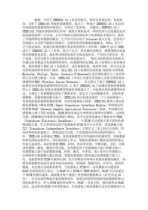
MTH01-SPI DATASHEET中英
CS, INPUT pin, has 100k pull up. Negative edge will wake up the module and send the previous measured data first, after that temperature and humidity measurement will take place. As long as CS is low, measure<->send data cycle is repeated. 首先发送先前测到的数据,然后再开始温度 和湿度的测量。只要 CS 拉低,测量,发数 据的过程就会一直持续下去。 SDAT and SCK, OUTPUT pin, is in CMOS output mode. Thus for external MCU connection, ports connecting to this two pins should be in input mode without pull high resister to avoid high current. 因此,对于外部的 MCU 连接,端口应该设 定在输入模式,不带内部上拉电阻以避免额 外电流产生 2.2.1 CS CS is to activate the sensor and triggers to send out the previous measured temperature and humidity value through SCK and SDAT line. After data sent out, an internal AD convert cycle will start automatically. If CS line is kept low after AD convert, the new measured data will be output through the data lines until CS
盛思锐 接口描述 Sensirion SCD30 传感器模块二氧化碳 温度传感器 用户说明书
Interface Description Sensirion SCD30 Sensor Module CO2, humidity, and temperature sensor▪NDIR CO2 sensor technology▪Integrated temperature and humidity sensor▪Best performance-to-price ratio▪Dual-channel detection for superior stability▪Small form factor: 35 mm x 23 mm x 7 mm▪Accuracy CO2 sensor: ± (30 ppm + 3%)▪Fully calibrated with digital interface UART or I2CContents1Digital interface description1.1 I2C Protocol1.2 Modbus protocol1.3 PWM protocol1.4 Sensor commands1.5 Signal conversion to physical values2Important Notices2.1 Warning, Personal Injury2.2 ESD Precautions2.3 Warranty3Headquarters and Subsidiaries1 Digital interface descriptionThe SCD30 digital interface is compatible with the I2C protocol and the Modbus protocol. For selecting Modbus protocol, the SEL pin needs to be pulled to VDD Voltage during power-up of the SCD30 sensor module. It is not possible to switch the communication protocol during operation. Please refer to datasheet.1.1 I2C ProtocolMaximal I2C speed is 100 kHz and the master has to support clock stretching . Sensirion recommends to operate the SCD30 at a baud rate of 50 kHz or smaller. Clock stretching period in write- and read-frames is 30 ms, however, due to internal calibration processes a maximal clock stretching of 150 ms may occur once per day. For detailed information to the I2C protocol, refer to NXP I2C-bus specification 1. SCD30 does not support repeated start condition. Clock stretching is necessary to start the microcontroller and might occur before every ACK. I2C master clock stretching needs to be implemented according to the NXP specification. The boot-up time is < 2 s. 1.1.1 I2C AddressAfter power-up of the sensor, the I2C address of the module is set to the address 0x61. 1.1.2 I2C SequenceThe commands issued by the I2C master are 16 bit with an optional parameter. Data sent to the master is protected by a CRC. This also applies to data arguments sent to the sensor, please see chapter 1.1.3 for CRC checksum calculation. 2 byte data sent from or received by the sensor is always succeeded with an 8 bit CRC. Examples are shown below.I2C write 16bit command without argumentsExample: Stop measurements 0x0104 START 0xC2 0x01 0x04 STOP(Red : Write Header; Blue : Read Header; Black: Data; Green : CRC; Start Condition: START; Stop Condition: STOP)1 /documents/user_manual/UM10204.pdfS W I2CAddress Cmd MSB A C KCmd LSBA C KClock Stretching P A C KI2C write 16bit command with argumentsExample: Trigger continuous measurement (Pressure = 0mBar) START 0xC2 0x00 0x10 0x00 0x00 0x81 STOP(Red : Write Header; Blue : Read Header; Black: Data; Green : CRC; Start Condition: START; Stop Condition: STOP)S W I2CAddress Cmd MSB A C KCmd LSB A C KClockStretchingA C KData0 MSBA C KData0 LSBA C KCRC0 PorData1 MSB A C KData1 LSB A C KCRC1 PorDataN MSBA C KDataN LSBA C KCRCNPA C KA C KA C KExample: Read Measurement (example with 439 PPM, 48.8% RH, 27.2 °C)Table 1 I2C write and read communication frames. SDA is controlled by the I2C master in clear blocks and by the sensor in dark blocks.1.1.3I2C Checksum calculationThe checksum byte for I2C communication is generated by a CRC algorithm with the following properties:1.2Modbus protocolFor selecting Modbus protocol, the SEL pin needs to be pulled to VDD Voltage. Please refer to datasheet.The supported baud rate is 19200 Baud with 8 Data bits, 1 Start bit and 1 Stop bit, no Parity bit.More details on the Modbus protocol can be found here:1.2.1Modbus addressModbus address is 0x61.1.2.2Modbus function codesAvailable function codes are1.3PWM outputThe SCD30 features the possibility to read out the CO2 concentration via the PWM protocol. During operation, the SCD30 must be connected via the VDD-pin (supply voltage), the GND-pin (ground) and the PWM-pin. Please refer to the data sheet for pin assignment.1.3.1Sensor configuration and measurement startThe SCD30 must be configured via the I2C or the Modbus protocol according to this interface description. This can either be done by the host system or alternatively in the assembly line with temporary connector pins. Sensor output is only provided after sending the start measurement command to the SCD30.1.3.2Technical specification PWM outputBelow, the technical specifications of the PWM protocol are provided. The output signal can be converted by either directly measuring the pulse-duration or alternatively by employing a low-pass filter and measuring the output voltage.t base1.3.3Low pass filter parametrizationTypically, the PWM signal is converted to a voltage signal via a low pass filter. Upon conversion of the PWM signal to a voltage signal the CO2 concentration is defined as follows: CO2 concentration [ppm] = V measure3⁄∗5′000.Since there’s an inherent trade-off between settling time, the ripple and the current consumption, the ideal parameterization of the low pass filter differs depending on the application. Nevertheless, an example parameter set for a first order low-pass is provided below:1.4Sensor commandsThe command set of the SCD30 is defined as follows. All commands are available via Modbus and I2C.-Trigger continuous measurement with optional ambient pressure compensation-Stop continuous measurement-Set measurement interval-Get data ready status-Read measurement-(De-)Activate continuous calculation of reference value for automatic self-calibration (ASC)-Set external reference value for forced recalibration (FRC)-Set temperature offset for onboard RH/T sensor-Altitude compensation-Read firmware version-Soft reset1.4.1Trigger continuous measurement with optional ambient pressure compensationStarts continuous measurement of the SCD30 to measure CO2 concentration, humidity and temperature. Measurement data which is not read from the sensor will be overwritten. The measurement interval is adjustable via the command documented in chapter 1.4.3, initial measurement rate is 2s.Continuous measurement status is saved in non-volatile memory. When the sensor is powered down while continuous measurement mode is active SCD30 will measure continuously after repowering without sending the measurement command. The CO2 measurement value can be compensated for ambient pressure by feeding the pressure value in mBar to the sensor. Setting the ambient pressure will overwrite previous settings of altitude compensation. Setting the argument to zero will deactivate the ambient pressure compensation (default ambient pressure = 1013.25 mBar). For setting a new ambient pressure when continuous measurement is running the whole command has to be written to SCD30.1.4.2Stop continuous measurementStops the continuous measurement of the SCD30.1.4.3 Set measurement intervalSets the interval used by the SCD30 sensor to measure in continuous measurement mode (see chapter 1.4.1). Initial value is 2 s. The chosen measurement interval is saved in non-volatile memory and thus is not reset to its initial value after power up.1.4.4Get data ready statusData ready command is used to determine if a measurement can be read from the sensor’s buffer. Whenever there is a measurement available from the internal buffer this command returns 1 and 0 otherwise. As soon as the measurement has been read by the return value changes to 0. Note that the read header should be send with a delay of > 3ms following the write sequence.1.4.5Read measurementWhen new measurement data is available it can be read out with the following command. Note that the read header should be send with a delay of > 3ms following the write sequence.Make sure that the measurement is completed by reading the data ready status bit before read out.I2C read-out stream:Table 2 shows the data layout of the data read out from the sensor.Using I2C for read-out the sensor will stream out the data in the given order.Table 2: I2C data read-out table. Read-out of measurement data can be aborted by sending a NACK followed by a stop condition after any data byte.Example: The CO2 concentration 400 ppm corresponds to 0x43c80000 in Big-Endian notation.Modbus read-out stream:Using Modbus for read-out the sensor will stream out the data in the given order.Table 3: Modbus data read-out table.21.4.6(De-)Activate Automatic Self-Calibration (ASC)Continuous automatic self-calibration can be (de-)activated with the following command. When activated for the first time a period of minimum 7 days is needed so that the algorithm can find its initial parameter set for ASC. The sensor has to be exposed to fresh air for at least 1 hour every day. Also during that period, the sensor may not be disconnected from the power supply, otherwise the procedure to find calibration parameters is aborted and has to be restarted from the beginning. The successfully calculated parameters are stored in non-volatile memory of the SCD30 having the effect that after a restart the previously found parameters for ASC are still present. Note that the most recently found self-calibration parameters will be actively used for self-calibration disregarding the status of this feature. Finding a new parameter set by the here described method will always overwrite the settings from external recalibration (see chapter 0) and vice-versa. The feature is switched off by default.To work properly SCD30 has to see fresh air on a regular basis. Optimal working conditions are given when the sensor sees fresh air for one hour every day so that ASC can constantly re-calibrate. ASC only works in continuous measurement mode. ASC status is saved in non-volatile memory. When the sensor is powered down while ASC is activated SCD30 will continue with automatic self-calibration after repowering without sending the command.Set Forced Recalibration value (FRC)Forced recalibration (FRC) is used to compensate for sensor drifts when a reference value of the CO2 concentration in close proximity to the SCD30 is available. For best results, the sensor has to be run in a stable environment in continuous mode at a measurement rate of 2s for at least two minutes before applying the FRC command and sending the reference value. Setting a reference CO2 concentration by the method described here will always supersede corrections from the ASC (see chapter 1.4.6) and vice-versa. The reference CO2concentration has to be within the range 400 ppm ≤ c ref(CO2) ≤ 2000 ppm.The FRC method imposes a permanent update of the CO2 calibration curve which persists after repowering the sensor. The most recently used reference value is retained in volatile memory and can be read out with the command sequence given below. After repowering the sensor, the command will return the standard reference value of 400 ppm.1.4.7Set Temperature OffsetThe on-board RH/T sensor is influenced by thermal self-heating of SCD30 and other electrical components. Design-in alters the thermal properties of SCD30 such that temperature and humidity offsets may occur when operating the sensor in end-customer devices. Compensation of those effects is achievable by writing the temperature offset found in continuous operation of the device into the sensor.Temperature offset value is saved in non-volatile memory. The last set value will be used for temperature offset compensation after repowering.1.4.8Altitude CompensationMeasurements of CO2 concentration based on the NDIR principle are influenced by altitude. SCD30 offers to compensate deviations due to altitude by using the following command. Setting altitude is disregarded when an ambient pressure is given to the sensor, please see section 1.4.1.Altitude value is saved in non-volatile memory. The last set value will be used for altitude compensation after repowering.1.4.9Read firmware versionFollowing command can be used to read out the firmware version of SCD30 module1.4.10Soft resetThe SCD30 provides a soft reset mechanism that forces the sensor into the same state as after powering up without the need for removing the power-supply. It does so by restarting its system controller. After soft reset the sensor will reload all calibrated data. However, it is worth noting that the sensor reloads calibration data prior to every measurement by default. This includes previously set reference values from ASC or FRC as well as temperature offset values last setting.The sensor is able to receive the command at any time, regardless of its internal state. In order to start the soft reset procedure the following command should be sent.1.5Signal conversion to physical valuesAll data read from the sensor are float numbers in big-endian format2. Conversion of digital values S x, (x = c(CO2), RH, T) to physical values and respective units are shown in the following tableTable 4: Signal conversion table.Conversation of temperature to °F as well as relative humidity to absolute humidity and dew point temperature can be found in Sensirion’s online support center3Sample pseudo code for converting data read from the sensor to physical value can be found below.// CO2 concentrationfloat co2Concentration;unsigned int tempU32;// read data is in a buffer. In case of I2C CRCs have been removed // beforehand. Content of the buffer is the followingunsigned char buffer[4];buffer[0] = 0x43; // MMSB CO2buffer[1] = 0xDB; // MLSB CO2buffer[2] = 0x8C; // LMSB CO2buffer[3] = 0x2E; // LLSB CO2// cast 4 bytes to one unsigned 32 bit integertempU32 = (unsigned int)((((unsigned int)buffer[0]) << 24) |(((unsigned int)buffer[1]) << 16) |(((unsigned int)buffer[2]) << 8) |((unsigned int)buffer[3]));// cast unsigned 32 bit integer to 32 bit floatco2Concentration = *(float*)&tempU32; // co2Concentration = 439.09f2IEEE 754 applies.3https:///fileadmin/user_upload/customers/sensirion/Dokumente/2_Humidity_Sensors/Sensirion_Humidity_Sensors_at_a_Glance_V1.pdfRevision History2Important Notices2.1Warning, Personal InjuryDo not use this product as safety or emergency stop devices or in any other application where failure of the product could result in personal injury. Do not use this product for applications other than its intended and authorized use. Before installing, handling, using or servicing this product, please consult the data sheet and application notes. Failure to comply with these instructions could result in death or serious injury.If the Buyer shall purchase or use SENSIRION products for any unintended or unauthorized application, Buyer shall defend, indemnify and hold harmless SENSIRION and its officers, employees, subsidiaries, affiliates and distributors against all claims, costs, damages and expenses, and reasonable attorney fees arising out of, directly or indirectly, any claim of personal injury or death associated with such unintended or unauthorized use, even if SENSIRION shall be allegedly negligent with respect to the design or the manufacture of the product.2.2ESD PrecautionsThe inherent design of this component causes it to be sensitive to electrostatic discharge (ESD). To prevent ESD-induced damage and/or degradation, take customary and statutory ESD precautions when handling this product.See application note “ESD, Latchup and EMC” for more information.2.3WarrantySENSIRION warrants solely to the original purchaser of this product for a period of 12 months (one year) from the date of delivery that this product shall be of the quality, material and workmanship defined in SENSIRION’s published specifications of the product. Within such period, if proven to be defective, SENSIRION shal l repair and/or replace this product, in SENSIRION’s discretion, free of charge to the Buyer, provided that:▪notice in writing describing the defects shall be given to SENSIRION within fourteen (14) days after their appearance;▪such defects shall be found, to SENSIRION’s reasonable satisfaction, to have arisen from SENSIRION’s faulty design, material, or workmanship;▪the defective product shall be returned to SENSIRION’s factory at the Buyer’s expense; and▪the warranty period for any repaired or replaced product shall be limited to the unexpired portion of the original period.This warranty does not apply to any equipment which has not been installed and used within the specifications recommended by SENSIRION for the intended and proper use of the equipment. EXCEPT FOR THE WARRANTIES EXPRESSLY SET FORTH HEREIN, SENSIRION MAKES NO WARRANTIES, EITHER EXPRESS OR IMPLIED, WITH RESPECT TO THE PRODUCT. ANY AND ALL WARRANTIES, INCLUDING WITHOUT LIMITATION, WARRANTIES OF MERCHANTABILITY OR FITNESS FOR A PARTICULAR PURPOSE, ARE EXPRESSLY EXCLUDED AND DECLINED.SENSIRION is only liable for defects of this product arising under the conditions of operation provided for in the data sheet and proper use of the goods. SENSIRION explicitly disclaims all warranties, express or implied, for any period during which the goods are operated or stored not in accordance with the technical specifications.SENSIRION does not assume any liability arising out of any application or use of any product or circuit and specifically disclaims any and all liability, including without limitation consequential or incidental damages. All operating parameters, including without limitation recommended parameters, must be validated for each customer’s applications by customer’s technical experts. Reco mmended parameters can and do vary in different applications.SENSIRION reserves the right, without further notice, (i) to change the product specifications and/or the information in this document and (ii) to improve reliability, functions and design of this product.Copyright© 2018, by SENSIRION.CMOSens® is a trademark of SensirionAll rights reserved3Headquarters and SubsidiariesSensirion AG Laubisruetistr. 50CH-8712 Staefa ZH Switzerlandphone: +41 44 306 40 00 fax: +41 44 306 40 30 ****************** Sensirion Inc., USAphone: +1 312 690 5858*********************Sensirion Korea Co. Ltd.phone: +82 31 337 7700~3*********************www.sensirion.co.kr Sensirion Japan Co. Ltd.phone: +81 3 3444 4940*********************www.sensirion.co.jpSensirion China Co. Ltd.phone: +86 755 8252 1501*********************Sensirion Taiwan Co. Ltd phone: +886 3 5506701****************** To find your local representative, please visit /distributors Version 1.0 – D1 – May 2020 21/21。
BME280环境传感器用户手册说明书
BME280 Environmental SensorUser ManualThe BME280 is as combined digital humidity, pressure and temperature sensor. Its small dimensions, low power consumption, high precision and stability allow the implementation in environmental monitor, whether forecast, altitude detection and IOT application.FEATURES⚫Support I2C interface, I2C device address could be set by changing I/O or welds⚫Supports SPI interface. Default I2C, you can change to SPI by change I/O⚫Integrated Level convert circuit, compatible with 3.3V/5V⚫Provide examples and user guide (Raspberry Pi/Arduino/STM32) SPECIFICATIONOperating voltage: 5V/3.3VInterface: I2C/SPITemperature range: -40~85°C (R esolution 0.1°C, tolerance±1°C)Humidity range: 0~100%rh (Resolution 0.008%RH, tolerance ±1°C)Pressure range: 300~1100hPa(Resolution 0.18Pa, tolerance ±1hPa)Dimensions: 27mmx20mmHoles size: 2.0mmINTERFACES I2CSPI:WORKING WITH RASPBERRY PIINSTALL LIBRARIESTo use examples we provide, you need to first install WiringPi library, or it could be be used normally. About how to install WiringPi library, you can visit the page: Libraries installation for RPi for details.EXAMPLE DOWNLOADVisit Our Wiki and find the page of BME280 Environmental Sensor, download the demo code.Extract it to get the folders as below:Copy Raspberry folder to your Raspberry Pi. You can copy it to the root of the TF card which you use for your Raspberry Pi.CONNECTION1.Enable I2C or SPI interface first,open configuration page with the command:sudo raspi-config2.Enable the interface separately.- For SPI: Choose Interfacing Options-> SPI -> Yes- For I2C (default): Choose Interfacing Options->I2C->Yes3.After configuring, reboot your Raspberry Pisudo reboot4.After rebooting, you can check if I2C or SPI module has been enabled withcommand (If there are I2C or SPI information printed, modules are started):lsmod5.Connet BME280 Environmental Sensor (called BME280) to your Raspberry Piaccording to the I2C table above.6.The address of I2C device is 0x77 by default. If you want to change it to 0x76, yucan connect ADDR to GND.7.Install I2C-tools tool, for I2C devices detectingsudo apt-get install i2c-tools8.You can query I2C devices with command:i2cdetect -y 1If there is 77 printed (76 if you change the address), it means that BME280 has connected to Raspberry Pi normally.Note: Please make sure that there are not other I2C devices which has the same address as BME280. For SPI connection, you can refer to the SPI table above.RUNNING DEMO CODE1.Connecting BME280 as above2.Enter directory of BME280-Environmental-Sensor-Demo-Code (which is includedin the folder we copied before):cd BME280-Environmental-Sensor-Demo-Code3.Open and edit file main.cvim main.c- If you use I2C connection which is default setting, you should set the USEIIC define to 1:Then check the address of I2C device on the code, the address used on code should be same as the one we detected before:- If you use SPI connection. You should change the USEIIC define to 0 on main.c:4.Save and exit. Then re-compile the demo code:sudo make cleansudo make5.Running the demo code:sudo ./bme280Note: if there are not any data outputted after running the demo code or get wrong data, please check the hardware connection and address used.WORKING WITH ARDUINO1.Open Arduino folder (from the one we download), Copy folder BME280-Arduino-Library to Libraries directory of IDE, which locates on installation directory of Arduino IDE.2.Open Arduino IDE, Choose File->Examples-> BME280_Libreay->bme280test toopen the demo code.3.Connect BME280 to Arduino according to Interfaces- By default, communication interface is I2C with device address 0x77- If you want to use SPI interface, you need to change USEIIC to 0 on demo code4.If you want to change the device address to 0x76, you could connect ADDR toND, and change the BME280_ADDRES value on Adafruit.h of demo code:5.If you want to get correct altitude data, you should first measure the atmospherepressure of local sea level and then change the define of SEALEVELPRESSURE_HPA6.Then compile and download to your Arduino board.7.Open Serial monitor and set the baud rate to 11520Note: if there are not any data outputted after running the demo code or get wrong data, please check the hardware connection and address usedWORKIGN WITH STM321.Open STM32 project which is under STM32 directory.2.Connect BME280 to STM32 board according to Interfaces3.Default interface is I2C with device address 0x77. If you change to SPI, you need tochange the USEIIR define to 0 of main.c:- If you want to use I2C and change its address, you can connect ADDR to GND and discommend statement dev.dev_id = BME280_I2C_ADDR_SEC:pile and download the demo code to STM32 board, the examples we provideis based on STM32F103RBT6, Use UART2 to print sensor data. You can connect UART to PC by TTL to UART module, then open Serial assistance software on PC,default 115200 8N1:Note: if there are not any data outputted after running the demo code or get wrong data, please check the hardware connection and address used.Libraries used In demo code is official library Bosch Sensortec:https:///BoschSensortec/BME280_driverFor SPI, its initial code:struct bme280_dev dev;int8_t rslt = BME280_OK;/* Sensor_0 interface over SPI with native chip select line */dev.dev_id = 0;dev.intf = BME280_SPI_INTF;dev.read = user_spi_read;dev.write = user_spi_write;dev.delay_ms = user_delay_ms;rslt = bme280_init(&dev);For I2C, its initial code:struct bme280_dev dev;int8_t rslt = BME280_OK;dev.dev_id = BME280_I2C_ADDR_PRIM;dev.intf = BME280_I2C_INTF;dev.read = user_i2c_read;dev.write = user_i2c_write;dev.delay_ms = user_delay_ms;rslt = bme280_init(&dev);bme280_dev is BME280 device structure provided by official library, could be used to initialize and obtain data. For different platform we should realize the functions below:user_i2c_read()user_i2c_write()user_spi_read()user_spi_write()user_delay_ms()And then transfer function pointers of these functions to bem280_dev structure. The function to read BME280 data is:int8_t stream_sensor_data_forced_mode(struct bme280_dev *dev)int8_t stream_sensor_data_normal_mode(struct bme280_dev *dev)Print function:void print_sensor_data(struct bme280_data *comp_data)The read/write function of I2C and SPI:void user_delay_ms(uint32_t period){/** Return control or wait,* for a period amount of milliseconds*/}int8_t user_spi_read(uint8_t dev_id, uint8_t reg_addr, uint8_t *reg_data, uint16_t len){int8_t rslt = 0; /* Return 0 for Success, non-zero for failure *//** The parameter dev_id can be used as a variable to select which Chip Select pin has* to be set low to activate the relevant device on the SPI bus*//** Data on the bus should be like* |----------------+---------------------+-------------|* | MOSI | MISO | Chip Select |* |----------------+---------------------|-------------|* | (don't care) | (don't care) | HIGH |* | (reg_addr) | (don't care) | LOW |* | (don't care) | (reg_data[0]) | LOW |* | (....) | (....) | LOW |* | (don't care) | (reg_data[len - 1]) | LOW |* | (don't care) | (don't care) | HIGH |* |----------------+---------------------|-------------|*/return rslt;}int8_t user_spi_write(uint8_t dev_id, uint8_t reg_addr, uint8_t *reg_data, uint16_t len){int8_t rslt = 0; /* Return 0 for Success, non-zero for failure *//** The parameter dev_id can be used as a variable to select which Chip Select pin has* to be set low to activate the relevant device on the SPI bus*//** Data on the bus should be like* |---------------------+--------------+-------------|* | MOSI | MISO | Chip Select |* |---------------------+--------------|-------------|* | (don't care) | (don't care) | HIGH |* | (reg_addr) | (don't care) | LOW |* | (reg_data[0]) | (don't care) | LOW |* | (....) | (....) | LOW |* | (reg_data[len - 1]) | (don't care) | LOW |* | (don't care) | (don't care) | HIGH |* |---------------------+--------------|-------------|*/return rslt;}int8_t user_i2c_read(uint8_t dev_id, uint8_t reg_addr, uint8_t *reg_data, uint16_t len){int8_t rslt = 0; /* Return 0 for Success, non-zero for failure *//** The parameter dev_id can be used as a variable to store the I2C address of the device*//** Data on the bus should be like* |------------+---------------------|* | I2C action | Data |* |------------+---------------------|* | Start | - |* | Write | (reg_addr) |* | Stop | - |* | Start | - |* | Read | (reg_data[0]) |* | Read | (....) |* | Read | (reg_data[len - 1]) |* | Stop | - |* |------------+---------------------|*/return rslt;}int8_t user_i2c_write(uint8_t dev_id, uint8_t reg_addr, uint8_t *reg_data, uint16_t len){int8_t rslt = 0; /* Return 0 for Success, non-zero for failure *//** The parameter dev_id can be used as a variable to store the I2C address of the device*//** Data on the bus should be like* |------------+---------------------|* | I2C action | Data |* |------------+---------------------|* | Start | - |* | Write | (reg_addr) |* | Write | (reg_data[0]) |* | Write | (....) |* | Write | (reg_data[len - 1]) |* | Stop | - |* |------------+---------------------|*/return rslt;}The basic flows to read BME280 data are:Step1: Initialize for OS and peripheralStep2: Realize Read, Write and Delay functions (I2C and SPI), and assignment the functions pointer to bme280_dev structure as publics, then transfer the pointer of structure to initialization function int8_t bme280_init(struct bme280_dev *dev). Initialize BME280 device.Step3: Calling int8_t stream_sensor_data_forced_mode(struct bme280_dev *dev) or int8_t stream_sensor_data_normal_mode(struct bme280_dev *dev) to get data of BME280 sensor and print them to console or PC.。
GDCB板故障---中文
仅适用于界面类型= 1。
显示驱动电池(aro-en)模式运行在48V直流电池
供应。登录时收到的驱动spbmode消息”batterymode”
从spbc3
012 LearnRun REQ
仅适用于界面类型= 1。
指示驱动器中的楼层表是无效的,这是一个新的学习运行
是必需的
Vac < 380,限值:115%正常电压
303 VAC Under
C
交流电源电压过低:
415 < Vac <= 480,限值:85%正常电压
380 <= Vac <= 415,限值:323 Vrms.
Vac <380,限值:85%正常电压
304 VACImbal
C
交流电源线电压差值大于10%
305 PLL Unlock
507posat1lsd只适用interfacetype1在突然的在1ls1ls到传感器检测到1ls信号但是不时所期望的位置信号但是不时所期望的位置508posat2lsd只适用interfacetype1在突然的在2ls2ls到传感器检测到1ls信号但是不时所期的位置信号信号但是不时所期的位置信号509floorat1lsd只适用interfacetype1在突然的在1ls1ls到传感器检测到1ls信号但是不时所期望的楼层信号但是不时所期望的楼层位置510floorat2ls只适用interfacetype1在突然的在2ls2ls到传感器检测到2ls信号但是不时所期望的楼层位置信号但是不时所期望的楼层位置5111lsamp
310 AC Brown-out
仅适用于接口类型1。
此警告指示该交流线路已下降15%,低于名义
AS1716 电容传感器接口说明书
AS1716Capacitive Sensor InterfaceDatasheet1 General DescriptionAS1716 is an analog front end specifically designed for unbiased Capacitive Sensors, as for instance Knock Sensors in Automotive, to be interfaced with Analog Digital Converters with Sample and Hold input stages.The device provides differential inputs, a 1st order low pass filter to cutoff the high frequency noise components, differential to single ended conversion, programmable gain stage and a 2 pole low pass Multiple Feedback Filter.The Knock Sensor is a Piezo Electric device that generates a voltage if it is stressed. It senses knock and transmits information to the elec-tronic engine management control unit. This influences process con-trol in the engine, for example timing and fuel injection until knock is eliminated.The capacitive sensor is biased via resistors to a voltage level of V DDA /2.Figure 1. AS1716 - Block Diagram2 Key FeaturesDifferential input stage with wide input range Resistive sensor biasing (V DDA /2) Programmable Gain (x0.5, x1, x2, x4) Internal 2ndorder low pass Multiple Feedback Filter with a min.cut off frequency of 16kHzSingle supply operation: 4.5V to 5.5V Operating Temperature range: -40°C to +125°C High CMRR: 55dB (min)EMC characterized by IEC 61967-4(1Ω / 150Ω Method)EMC characterized by IEC 62132-4(Direct Power Injection)Automotive qualified to AECQ100 for IC and PPAP level 3 8-pin SOIC Package3 ApplicationsAnalog front end for Capacitive Sensors to Analog to Digital Convert-ers and DSP.+--+-+VDDAVDDA/2Multiple Feedback LP Filterfc ~23kHz typ.INPGA GBOUTNCVSSAVDDAGain Control x0.5, x1, x2, x4-+VDDA/2VDDA/2VDDA/2-+VDDA/2INNAS1716Datasheet - P i n o u t4 PinoutPin AssignmentFigure 2. Pin Assignments (Top View)Pin DescriptionTable 1. Pin DescriptionPin Name Pin NumberDescriptionVDDA 1Positive SupplyGA 2Gain selection. Internal pull-down of 100k ΩGB 3Gain selection. Internal pull-down of 100k ΩINP 4Non-Inverting Input INN 5Inverting InputNC 6Not Connected. Must be left unconnected in the application VSSA 7Negative Supply OUT8Signal OutputOUT VSSANC INNVDDA GAGB INP AS171612348765Datasheet - A b s o lu t e M a x im u m R a ti n g s5 Absolute Maximum RatingsStresses beyond those listed in Table 2 may cause permanent damage to the device. These are stress ratings only, and functional operation of the device at these or any other conditions beyond those indicated in Electrical Characteristics on page 4 is not implied. Exposure to absolute maximum rating conditions for extended periods may affect device reliability.Table 2. Absolute Maximum RatingsParameter Min Max Units CommentsElectrical ParametersVDDA, VSSA+7VGA, GB, OUT, INP, INN, NC VSSA -0.3VDDA +0.3VTo get an overvoltage protection of up to +16V at thesystem level, apply external resistors (typ. 1kΩ) on thepins INP and INN.Input Current (latch-up immunity)-100+100mA Norm: AEC-Q100-004, @ T A = +25ºC Electrostatic DischargeElectrostatic Discharge HBM±4kV Norm: AEC-Q100-002, @ T A = +25ºC Temperature Ranges and Storage ConditionsStorage Temperature Range-65+150ºCJunction Temperature+150ºCPackage Body Temperature +260ºCThe reflow peak soldering temperature (bodytemperature) specified is in accordance with IPC/JEDEC J-STD-020 “Moisture/Reflow Sensitivity Classification for Non-Hermetic Solid State SurfaceMount Devices”.The lead finish for Pb-free leaded packages is matte tin(100% Sn).Humidity non-condensing585%Moisture Sensitive Level3Represents a max. floor life time of 168hDatasheet - E l e c t r i c a l C h a r a c t e ri st i c s6 Electrical CharacteristicsParameters are measured at V DDA = 4.5V to 5.5V, R LOAD = 100Ω serial to C LOAD = 10nF, T A = +25ºC and are refering to VSSA, unless other-wise specified. Typical values are listed for reference only and will not be tested.All limits are guaranteed. The parameters with min and max values are guaranteed with production tests or SQC (Statistical Quality Control) methods.Table 3. Electrical Characteristics Symbol ParameterCondition Min Typ Max Unit T AMB Operating Temperature Range -45+125°C DC Electrical CharacteristicsV DDA Supply Voltage Range @ pin VDDA 4.55 5.5V I DDA Supply Current @ pin VDDA34.59mA PSRR 11.Guaranteed by designPower Supply Rejection Ratio 6dB V CM Common Mode input Range @ pins INN, INP V SSA V DDAV CMRR Common Mode Rejection Ratio 55dB R IN Differential Input Resistance between pins INN and INP 70100130k ΩV REF Internal Common Mode InputVoltageINP shorted to INNV DDA /2 -2%V DDA /2V DDA /2 +2%V V OFF Offset Voltage Gain1, V INP = V INN @ V CM = V DDA /2,@ pin OUTV REF -10V REF +10mV V IL Logic Low (GA, GB)@ pin GA and GB 1.2V V IH Logic High (GA, GB)@ pin GA and GB 2.0V I LEAK Leakage Current (GA, GB)V DDA = 5V, Gain41µA V HYST 1Hysteresis @ pin GA and GB 100200mVR PD Pull-Down Resistor @ pin GA and GB 50100150k ΩGain0.5Overall gain 0.5GA = GB = 10.5-10%0.50.5+10%Gain1Overall gain 1GA = 1, GB = 01-10%11+10%Gain2Overall gain 2GA = 0, GB = 12-5%22+5%Gain4Overall gain 4GA = GB = 0, default setting 4-5%44+5%R L External Serial Resistor R L serial to C L (see Figure 13 on page 8)1001k ΩC L External Capacitive Load 0.0110nF I SHORT+Positive Short Circuit Current V OUT is driven to V DDA and V OUT is connectedto V SSA 25mA I SHORT-Negative Short Circuit CurrentV OUT is driven to V SSA and V OUT is connectedto V DDA25mA V OUT-L Output Range Low @ pin VOUT V SSA +0.05V V OUT-HOutput Range High@ pin VOUTV DDA -0.05VAC Electrical Characteristicsf C Filter Cut-off Frequency V DDA = 4.5V, GA = GB = 0, INP-INN = 1V PP, f IN= 16kHz and 29kHz 162329kHz THD Total Harmonic Distortion V DDA = 5V, f IN = 1kHz, INP-INN = 8V PP , Gain0.580dB V NOISERMS noise at OUTGain4, f C = 50Hz - 23kHz1mV RMSDatasheet - Ty p i c a l O p e r a t i n g C h a r a c t e r i s t i c s7 Typical Operating Characteristics V DDA = 5.0V, T A = +25ºC (unless otherwise specified).8 Detailed DescriptionSensor Biasing and Input Protection ResistorsDue to the capacitive and differential nature of the knock sensor, the common mode voltage for the sensor must be set. This is ensured by the first amplifier, whose virtual ground is biasing the sensor via a of 50k Ω resistor. Due to a failure, voltages up to 16V can occur on the input pins. In this case two external serial resistors of 1k Ω must be applied at the inputs. These resistors are limiting the current, when the on chip protec-tion diode opens.Figure 9. Sensor BiasingInverting Input StructureThe Input Strucutre is a first order low-pass filter and fulfills two main functions. First, it is used for biasing the sensor and second, the first order low-pass filter characteristic is used for noise suppression. Figure 10. Input BufferDue to failure up to 16V560k1200p Ftypical sensor100p F1k 100p F1k INNINP+-VDDAVDDA/2-+VDDA/2-+VDDA/2-+VDDA/2Fully Differential to Single Ended ConversionThe Subtractor block converts the filtered differential sensor signal into a single ended signal. Further this block provides also the gain setting (see Section Gain Settings). Figure 11. Subtractor BlockGain SettingsBy means of pins GA and GB, 4 gain settings (x0.5, x1, x2, x4) can be realized. The default gain setting is 4, GA=0 and GB=0.Multiple Feedback FilterThe Multiple Feedback Filter provides a second order low pass characteristics with a minimum cut-off frequency of 16kHz and a typical f C of 23kHz. The Multiple Feedback configuration is used to avoid aliasing, to filter out high frequency components. The Output is able to drive a resis-tor from 100Ω to 1k Ω serial to a 10nF capacitor.Figure 12. Multiple Feedback FilterTable 4. Gain SettingsGain GA GB 0.5111102014-+Gain Control x0.5, x1, x2, x4-+OUTMultiple Feedback LP filterfc ~23kHz typ.VDDA/29 Application InformationFigure 13. Application Diagram, minimal requirementsValues of the suggested external components are indicative and need to be characterized for each specific application.Typical Piezo Sensor:Resistor from 500k Ω to 1M Ω Capacity from 900nF to 1.5µFTypical wire equivalent circuit:Capacity to groung from 100pF to 400pF / meterCapacity between wires strongly depends on type of wires (twisted-pair strongly suggested) Resistance is typical 50m Ω / meter @ 20°CLayout rulesInput Resistors and Capacitors at the inputs should be placed as close as possible to the stonger possible source of disturbances (i.e. theinput connector).The input lines should be kept as short as possible and routed close to each other.The filter capacitor (100nF) on supply should be a ceramic type and placed as close as possible to the chip.VSSA and VDDA lines on PCB should have larger width than other signals to minimize resistance, especially if the 10µF capacitor is notvery close to the chip.The output line should be kept as short as possible.Due to failure up to 16V560k1200p Ftypical sensor100p F1k 100p F1k -+Multiple Feedback LP filterfc ~23kHz typ.Gain Control x0.5, x1, x2, x4INNINPGA GB100Ωto 1kOUT10n F µC12 Bit AD 50k S/sNCVSSAVDDA 100nF 10µFV 4.5...5.5V-+-+VDDA/2-+VDDA/2+-VDDAVDDA/2VDDA/2VDDA/2AS171610 Package Drawings and MarkingsTable 5. Packaging Code YYWWMZZYY WW M ZZ last two digits of the current year manufacturing week plant identifier free choice / traceability codeDatasheet - O r d e r i n g I n f o rm a t i o n11 Ordering InformationThe device is available as the standard product shown in Table 6.Table 6. Ordering InformationOrdering Code Marking Description Delivery Form Package AS1716-ASOT AS1716Capacitive Sensor Interface, 16kHz Tape and Reel8-pin SOICNote:All products are RoHS compliant.Buy our products or get free samples online at ICdirect: /ICdirectFor further information and requests, please contact us mailto:*****************************or find your local distributor at /distributorDatasheetCopyrightsCopyright © 1997-2011, austriamicrosystems AG, Tobelbaderstrasse 30, 8141 Unterpremstaetten, Austria-Europe. Trademarks Registered ®. All rights reserved. The material herein may not be reproduced, adapted, merged, translated, stored, or used without the prior written consent of the copyright owner.All products and companies mentioned are trademarks or registered trademarks of their respective companies.DisclaimerDevices sold by austriamicrosystems AG are covered by the warranty and patent indemnification provisions appearing in its Term of Sale. austriamicrosystems AG makes no warranty, express, statutory, implied, or by description regarding the information set forth herein or regarding the freedom of the described devices from patent infringement. austriamicrosystems AG reserves the right to change specifications and prices at any time and without notice. Therefore, prior to designing this product into a system, it is necessary to check with austriamicrosystems AG for current information. This product is intended for use in normal commercial applications. Applications requiring extended temperature range, unusual environmental requirements, or high reliability applications, such as military, medical life-support or life-sustaining equipment are specifically not recommended without additional processing by austriamicrosystems AG for each application. For shipments of less than 100 parts the manufacturing flow might show deviations from the standard production flow, such as test flow or test location.The information furnished here by austriamicrosystems AG is believed to be correct and accurate. However, austriamicrosystems AG shall not be liable to recipient or any third party for any damages, including but not limited to personal injury, property damage, loss of profits, loss of use, interruption of business or indirect, special, incidental or consequential damages, of any kind, in connection with or arising out of the furnishing, performance or use of the technical data herein. No obligation or liability to recipient or any third party shall arise or flow out of austriamicrosystems AG rendering of technical or other services.Contact InformationHeadquartersaustriamicrosystems AGTobelbaderstrasse 30A-8141 Unterpremstaetten, AustriaTel: +43 (0) 3136 500 0Fax: +43 (0) 3136 525 01For Sales Offices, Distributors and Representatives, please visit:/contact。
- 1、下载文档前请自行甄别文档内容的完整性,平台不提供额外的编辑、内容补充、找答案等附加服务。
- 2、"仅部分预览"的文档,不可在线预览部分如存在完整性等问题,可反馈申请退款(可完整预览的文档不适用该条件!)。
- 3、如文档侵犯您的权益,请联系客服反馈,我们会尽快为您处理(人工客服工作时间:9:00-18:30)。
美国Interface传感器、Interface称重传感器、Interface悬臂梁式称重传感器、Interface柱式称重传感器、Interface轮辐式称重传感器、Interface拉压式称重传感器、Interface不锈钢称重传感器、Interface特殊称重传感器。
上海秋腾贸易有限公司特价代理美国Interface传感器、Interface称重传感器、Interface悬臂梁式称重传感器、Interface柱式称重传感器、Interface轮辐式称重传感器、Interface拉压式称重传感器、Interface不锈钢称重传感器、Interface特殊称重传感器
Interface 公司提供了全系列力传感器,扭矩传感器,仪器仪表,配件,以满足所有的力和扭矩传感器测量的需要。
当你需要一个测力、扭矩或者一个高精度的传感器,可以考虑选择Interface产品,它具有以下优点:
我们应用我们自己的专利合金技术生产独一无二的专利应变片。
安装有专利技术应变片的传感器,意味着具有更好的耐温性,较长的疲劳寿命和更高的输出电压(最多4mV/V)领先我们的竞争对手。
我们测试和校准每一个出厂的传感器-我们不是抽检。
你可以肯定你订购的传感器达到我们的设计指标和你的预期。
我们每个传感器都采用补偿技术。
使外界的干扰对传感器的影响最小化。
我们还对每个传感器进行蠕变测试,使其达到在业内最严密的规范。
Quality is our obsession!我们为质量不懈努力!。