maxonDCmotor笔记
maxon epos4 定位控制器使用 ni labview 和 ni 工业通信进行同步控制说明书
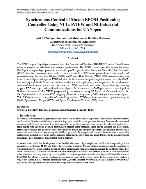
Synchronous Control of Maxon EPOS4 PositioningController Using NI LabVIEW and NI IndustrialCommunications for CANopenAsif Al Zubayer Swapnil and Mohammad Habibur RahmanDepartment of Mechanical EngineeringUniversity of Wisconsin-MilwaukeeMilwaukee, WI, USA,AbstractThe EPOS range of digital position controllers for Brushed and Brushless DC (BLDC) motors from Maxon group is popular in industrial and robotics applications. The EPOS4 series provides option for using CANopen, a higher layer protocol, and device profile specifications based on Controller Area Network (CAN) bus for communication with a master controller. CANopen protocol uses two modes of communication, Service Data Objects (SDO) and Process Data Objects (PDO). SDO communication can be used to configure and operate EPOS4 devices in the network in a point-to-point manner over the CAN-bus, making it difficult for use in real-time motion control applications, and impossible for synchronous control of multi-motor systems over the same bus. PDO communication solves the problem by allowing mapped PDO messages and synchronization objects. In this research, a CANopen master is developed in National Instruments’ LabVIEW programming environment using NI-Industrial Communications for CANopen module with custom PDO mappings, Network management (NMT) and synchronization objects. This CANopen master is capable of controlling multiple EPOS4 position controllers synchronously in Cyclic Synchronous Torque (CST), and Cyclic Synchronous Position (CSP) mode.KeywordsCANopen, LabVIEW, Industrial Communication, Positioning Controller, EPOS1. IntroductionIn robotics, servo motors with precise position control is a matter of utmost importance. Historically, the servo motors are driven by Field Oriented Control method using servo amplifiers, and position feedback from encoders mounted on motor shaft is used in a central position controller to precisely control robot motion. In industrial applications, servo drives with integrated position control have become more common. These drives integrate the motor drive, feedback processing, and position control for one motor axis in one integrated package. And multiple drives can be networked with industrial networking and Fieldbus protocols for complicated and distributed motion control with motor drives mounted close to the motors reducing cable length, power loss, and noise. But due to the size and weight constraints, these controllers are not often used in robotics.In recent times with the development of embedded electronics, lightweight and small-scale integrated position controllers, e.g., Maxon EPOS, and Odrive have become available. The use of these position controllers can lead to weight and energy-saving benefits as well as better performance with local position control. In the BioRobotics Lab at the University of Wisconsin-Milwaukee, we have developed a functional exoskeleton robot and a small manipulator robot which are currently driven by servo amplifiers. A central position controller developed in National Instrument LabVIEW Real-Time is used to synchronously control all joints of these two robots. In this research, we explore a way to get Maxon EPOS4 position controllers with CANopen interface work with LabVIEW in order to evaluate the possibility of using these position controllers to operate these robots in the future.2. Literature Review2.1 CAN-bus and CANopen protocolThe Controller Area Network or CAN-bus is a serial bus protocol used in the automotive industry since its introduction in 1986 by Robert Bosch GmbH (Pfeiffer et al. 2008). The CAN-bus specifications cover the lower two layers (physical and datalink layers in the OSI model of communication protocols. In automotive industry different manufacturers have their own proprietary protocols built upon this specification to take over the functionality of higher layers of the OSI model. For use in automation, ‘CAN in Automation’ of ‘CiA’ has developed a standard protocol called CANopen (CiA Draft Standard 301) that takes care of the upper 5 layers (Network, Transport, Session, Presentation, and Application) of the OSI model (National Instruments 2020). In the CANopen protocol published in the CiA 301 specifications, the following concepts are used to describe the communication method used by CANopen. Object Dictionary (OD)In a CANopen device, an Object Dictionary (OD) must be used to hold all the configuration data and process data in an organized manner. The object dictionary can be conceptualized as a 3-dimensional table with a 16-bit index and 8-bit sub-index to address all of the data contained in the dictionary. CiA 301 standard defines some of these indices (CiA Draft Standard 301) for a predetermined data type, and other ranges of indices are open for manufacturers to implement required process data and configurations. By accessing this object dictionary or each node in the network, the relevant information can be read or written on that device (CiA Draft Standard 301, National Instruments 2020). CANopen messagesIn CANopen message frame is formatted based on CAN data frame format where 11-bit CAN ID is repurposed as a communication object identifier, otherwise known as COB-ID, combining a 4-bit function code for the CANopen message with a 7-bit node-id unique for each node of the network (CiA Draft Standard 301). This specification makes sure the same message from different nodes can be identified uniquely by their COB-ID to avoid conflicts in the network. The 7-bit node-id makes it possible for a CANopen network to contain up to 127 nodes.SDO and PDOThe two most important types of communication objects used in CANopen are Service Data Objects (SDO) and Process Data Objects (PDO). These are used for transferring data between two or multiple nodes in a CANopen network. Depending on their characteristics, they are used exclusively in different modes of network operation. An SDO is used for peer-to-peer communication in a client-server model as seen in figure 1 (Maxon motor ag. 2019). In SDO communication, any node in the network can act as a server for their object dictionary, and another node acts as a client to request data to be reador written from a specific index and sub-index of the server’s object dictionary. For each data transaction, the client initiates the SDO communication with a CANopen message with COB-ID formed by combining the CAN ID 600h + node ID of the server. The server with the correct node ID responds with a reply message with COB-ID formed by CAN-ID 580h + node ID of the server. Depending on the type of data transfer, SDO write or SDO read, one message will contain the data, and another will contain an acknowledge message.Figure 1. Service Data Object (SDO) [Adapted from Maxon motor ag "EPOS4 Positioning ControllersCommunication Guide", Edition 2019-11, Doc ID: rel8759]For real-time control operations, SDO communication is not suitable as it requires a lot of time and bandwidth for updating single process variable to each node of the network. In those applications, PDO based communication is used, where the network nodes work in a producer-consumer model. In this case, a PDO message is produced by the consumer and based on COB-ID of the message; it is consumed by multiple consumers in the network as seen infigure 2 (Maxon motor ag. 2019). A PDO producer can generate a PDO message based on different triggers. The triggers can be external events, for example, status change of a digital input, it can be a remote request from a node in the network, or it can be periodic updates using timed SYNC messages in the network.Figure 2. Process Data Object (PDO) [Adapted from Maxon motor ag "EPOS4 Positioning ControllersCommunication Guide", Edition 2019-11, Doc ID: rel8759]PDO Mapping and PDO LinkingIn CiA301 specification, the PDO messages are classified in two types, Receive PDO (RPDO) and Transmit PDO (TPDO) (Pfeiffer et. al. 2008, CiA Draft Standard 301). A TPDO is a PDO configured on the producer with its own COB-ID, and an RPDO is a PDO configured in a PDO consumer with a COB-ID set to match the COB-ID of a TPDO in another PDO producer in a network. The process of configuring the RPDO on the consumer to match the correct TPDO on the producer is called PDO linking. To use PDO communication to update process data of different nodes in the network, each PDO messages in the network needs to be mapped to a relevant entry on the node’s OD with correct Index and Sub-index. Typically, TPDOs are mapped to process variables that the node updates by itself during operation, and RPDOs are mapped to process variables updated by the central controller.SYNC and NMT objectsThe other two important communication objects used to facilitate the PDO communication in real-time control applications are SYNC (Synchronization) and NMT (Network Management) objects. SYNC objects are produced by a SYNC producer to trigger any event, e.g., sampling of an analog input or transmitting a TPDO on all SYNC consumer nodes in the network. In CANopen, the NMT communication objects create a master/slave configuration where an NMT master controls the operational states of the NMT slaves, as seen in figure 3 (Maxon motor ag. 2019). In the initialization state, the slaves announce their presence and Node-ID in the network. In the Pre-operational state, only SDO communication is possible alongside NMT messages. In the Operational state, SYNC and PDO communications are possible. In a Stopped state, both PDO and SDO communications are blocked, and only NMT communication can take place to change the state again.Figure 3. NMT slave states [Adapted from Maxon motor ag "EPOS4 Positioning Controllers CommunicationGuide", Edition 2019-11, Doc ID: rel8759]In our application, the synchronous control of the EPOS4 devices in the network was achieved using TPDO messages to update the target position or torque and RPDO messages to read the actual position and torque values, triggered by SYNC messages from the Network Master.2.2 EPOS4 positioning controllerEPOS4 positioning controllers from Maxon motor ag are compact servo positioning controllers capable of controlling position, velocity or torque of permanent-magnet brushless DC (BLDC) motors in servo operation. Thecommunication interface of EPOS4 controllers conforms to the CiA 301 “CANopen application layer and communication profile” as well as CiA 402 “CANopen device profile for drives and motion control” (CiA Draft Standard 402, Maxon motor ag. 2018a), making it an ideal candidate for real-time control operations for motion application through CANopen.Figure 4. EPOS4 CiA402 Device State Machine [Adapted from Maxon motor ag "EPOS4 Positioning Controllers EPOS4 Firmware Specification", Edition 2018-11, Doc ID: rel8234]CiA 402 device profileCiA 402 device specifications are published as a device profile for frequency inverters and motor drives to be used in the CANopen network. This device profile includes operation-specific PDO mappings and an operational-state-machine for motor control operation seen in figure 4 (CiA Draft Standard 402, Maxon motor ag. 2018a). Operation ModesBeing designed as a versatile position controller for automation and robotics application, the EPOS4 controllers offer multiple modes of operation, each controlling either position, velocity, or torque of a permanent magnet BLDC motor. It offers two profile modes (position and velocity), three cyclic synchronous modes (position, velocity, and torque) and one homing mode. For our robotics operation, Cyclic Synchronous Position (CSP) and Cyclic Synchronous Torque (CST) modes are of particular interest. In CSP mode, the EPOS4 input process variables are ‘target position’, ‘position offset’, and ‘torque offset’, and the output process variables are ‘position actual value’, ‘velocity actual value’, and ‘torque actual value’. Figure 5 shows the CSP mode controller configuration with the object dictionary indices of each process variable (Maxon motor ag. 2018a).Figure 5. Cyclic Synchronous Position Mode – Overview [Adapted from Maxon motor ag "EPOS4 Positioning Controllers EPOS4 Firmware Specification", Edition 2018-11, Doc ID: rel8234]In CST mode, only target torque and torque offset are used as input process variables, and actual position, velocity, and torque are again the output process variables, as seen in figure 6 with the OD indices.Figure 6. Cyclic Synchronous Torque Mode – Overview [Adapted from Maxon motor ag "EPOS4 Positioning Controllers EPOS4 Firmware Specification", Edition 2018-11, Doc ID: rel8234]In EPOS4 controllers, all three Cyclic Synchronous modes have their input process variables internally refreshed in 1 millisecond cycle time (Maxon motor ag. 2018b), limiting the fastest effective bandwidth for a central closed-loop controller in the network to 1 kHz.2.3 NI Industrial Communications for CANopenNational Instruments’ (NI) LabVIEW software is a popular programming environment for instrumentation and control prototyping. NI Industrial Communications for CANopen (National Instruments 2020b) is an add-on library adding the functionality of using CANopen communication in LabVIEW programming environment. Paired with a NI real-time controller and a CANopen interface hardware, it is possible to build a CANopen network master capable of controlling multiple CANopen slave nodes in a real-time control network.3. MethodsIn our experimental setup shown in figure 7, a NI PXIe-8135 real-time controller equipped with a NI PXI-8531 CANopen interface module is used to operate multiple EPOS4 test setups in the same CANopen network. A CANopen master application, shown in figure 8, was developed capable of controlling the NMT state of the network, the CiA 402 state of each EPOS4 unit, and synchronously control all the EPOS4 units in the network in CST mode.Figure 7. Experimental SetupAn IXXAT ‘USB-to-CAN’ module was also connected with the ‘CAN Analyzer Mini’ software to monitor CAN-bus usage. It was observed that with 1-3 motors active in the network, cycle times of 1ms was easily achieved. But with more than three motors active in the network, the highest available CAN-bus baud rate of 1 Mbit/s was being saturated, and the cycle time of the network had to be slowed down with each additional motor.Figure 8. User interface for the LabVIEW program developed for this research4. Discussion4.1 Proposed Future WorkWe are working towards replacing analog servo amplifiers used in two functional robots at the University of Wisconsin-Milwaukee BioRobotics Lab with EPOS4 controllers in a CANopen network. On completion of that, the robots will be operated with the EPOS4 controllers in CSP as well as in CST mode with a central position controller, and the trajectory tracking performance will be compared with current analog servo amplifier-based setup. With the comparison, any performance change introduced by data transfer delays and bandwidth limitations will be explored.5. ConclusionWith this research, we have explored a way to control multiple EPOS4 controllers with the CANopen interface from LabVIEW programming environment. This confirms the viability of using these position controllers in our robot. However, the bandwidth and cycle time limitations need to be further explored to verify the position tracking the performance of this configuration compared to the existing analog servo amplifier-based setup.PXIe-8135 RT Controller with PXI-8531 CANopen ModuleIXXATUSB-to-CAN EPOS4 EPOS4 EPOS4EPOS4 120 o h m s 120 ohmsReferencesPfeiffer, O., Ayre, A. & Keydel, C. Embedded Networking with CAN and CANopen, Copperhill Technologies Corporation, 2008“CANopen application layer and communication profile”, CiA Draft Standard 301, Version 4.02“The Basics of CANopen”. National Instruments. https:///en-us/innovations/white-papers/13/the-basics-of-canopen.html (July 23, 2020)Maxon motor ag EPOS4 Positioning Controllers Communication Guide, Edition 2019-11, Doc ID: rel8759 “CANopen device profile for drives and motion control”, CiA Draft Standard 402, Version 4.00Maxon motor ag "EPOS4 Positioning Controllers EPOS4 Firmware Specification", Edition 2018-11, Doc ID: rel8234Maxon motor ag EPOS4 Positioning Controllers EPOS4 Feature Chart, Edition 2018-11, Doc ID: rel8001“NI-Industrial Communications for CANopen 20.0 Readme”. National Instruments./pdf/manuals/375165h.html (July 23, 2020)BiographiesAsif Al Zubayer Swapnil is a graduate student in the Mechanical Engineering Department of University of Wisconsin-Milwaukee. Currently he is working for his MS the BioRobotics lab under supervision of Dr. Rahman. He received his BSc. Engineering (mechanical) degree from Khulna University of Engineering & Technology, Bangladesh in 2014. He worked as an industrial and mechatronic system designer in product design industries for 4 years. His research interests include mechatronic and robotic systems for rehabilitation and assistance persons with physical disabilities.Mohammad Habib Rahman is with the Mechanical and Biomedical Engineering Department, University of Wisconsin-Milwaukee, WI, USA. As Director of the BioRobotics Lab at the University of Wisconsin-Milwaukee, he brings the resources and expertise of an interdisciplinary R&D team. For more than 15 years he has been researching bio-mechatronics/bio-robotics with emphasis on the design, development and control of wearable robots to rehabilitate and assist elderly and physically disabled individuals who have lost their upper-limb function or motion due to stroke, cardiovascular disease, trauma, sports injuries, occupational injuries, and spinal cord injuries. He received a BSc Engineering (mechanical) degree from Khulna University of Engineering & Technology, Bangladesh in 2001, a Master of Engineering (bio-robotics) degree from Saga University, Japan in 2005 and a PhD in Engineering (bio-robotics) from École de technologie supérieure (ETS), Université du Québec, Canada in 2012. He worked as a postdoctoral research fellow in the School of Physical & Occupational Therapy, McGill University (2012-2014). His research interests are in bio-robotics, exoskeleton robot, intelligent system and control, mobile robotics, nonlinear control, control using biological signal such as electromyogram signals.。
奔驰车系故障诊断笔记5

图21 堵塞管路在电动助力泵上的安装位置向盘沉重。
故障12
关键词:附加蓄电池、车载蓄电池
故障描述:一辆2013年产奔驰GLK260运动型多功能车,搭载2.0T 发动机和手自一体变速器,行驶里程89 764 km,用户投诉ECO功能失效。
检查分析:维修人员接车后首先查看该车的维修记录,此车2个月前来店里检查过此问题,当时更换了奔驰原厂
评估所有相关的影响因素,然后发出起且车载电气系统电压足够高时,附加蓄
N10/1——前SAM控制单元 F25/1——附加蓄电池继电器30回路附加熔丝 G1/13——ECO功能附加蓄电池 U1092——不适用于车型204.9 U25——适用于自动变速器 。
Electric Motor

The commutator works by connecting the wire ends to the input power through brushes. Brushes used to be literally copper brushes, but are now replaced with carbon pads. These brushes slide over rotating rings called slip rings that are attached to the rotor and divided into two parts. When one part is in contact with the positive brush, the current flows into one end of the copper wire. The other end is in contact with the negative end of the brush to complete the circuit. As the loop reaches alignment, the gap in the ring reaches both brushes and the current is short circuited. After the loop moves past the aligned position, the gap has past the brushes and the other side of the slip ring is in contact causing the current to flow in the other direction. Increasing the number of coils in the rotor is a good way to improve the performance of a DC motor giving more constant torque as the rotor rotates. For each loop added the commutator must be upgraded and additional brushes are required. Additional poles can also be added to the stator.
马达电路的知识点总结
马达电路的知识点总结1. 直流电动机驱动电路直流电动机驱动电路通常由电源、开关、电阻、电容、继电器、变压器、整流器、PWM调速器等组成。
其中,电源提供电能,开关用于实现启停功能,电阻和电容用于保护电机,继电器用于实现正反转功能,变压器用于降压升压,整流器用于将交流电转换为直流电,PWM调速器用于实现电机的调速功能。
直流电动机驱动电路的工作原理是:当电源接通后,通过开关控制电机的启停功能,通过PWM调速器控制电机的转速,通过继电器控制电机的正反转功能。
通过合理的设计和控制,可以实现对直流电动机的精准控制。
2. 交流电动机驱动电路交流电动机驱动电路通常由电源、开关、变压器、整流器、PWM调速器、频率变换器等组成。
其中,变压器用于降压升压,整流器用于将交流电转换为直流电,PWM调速器和频率变换器用于控制电机的转速。
交流电动机驱动电路的工作原理是:同样通过开关控制电机的启停功能,通过PWM调速器和频率变换器控制电机的转速。
与直流电动机不同的是,交流电动机在控制时需要考虑到电机的相序、起动电流、定位精度等问题。
因此,交流电动机驱动电路在设计和控制上更为复杂。
3. 马达控制技术马达控制技术包括开环控制和闭环控制两种方式。
开环控制是指在没有反馈的情况下对电机进行控制,通常通过PWM调速器或频率变换器来实现。
闭环控制是指在有反馈的情况下对电机进行控制,通常通过编码器、霍尔传感器等装置来实现。
在马达控制技术中,PID控制是一种常用的闭环控制方法。
PID控制是指通过比例、积分、微分三个参数来调节电机的转速,以实现稳定的控制效果。
此外,矢量控制、矢量调速、磁场定向等技术也是马达控制中常用的方法。
总结马达电路作为电机控制的核心部分,在工业生产、家用电器、汽车等领域有着广泛的应用。
合理的设计和控制马达电路,能够提高设备的运行效率、可靠性和安全性。
因此,掌握马达电路的知识点,是电气工程领域工程师和技术人员必备的基本技能。
同时,随着科技的不断发展,马达电路的控制技术也在不断创新和完善,为提高电机的控制精度和效率提供了更多的可能性。
Motorknowledge马达常识资料
目录操作 (3)三要素相互作用产生传动 (3)直流电机主要部件 (4)交流电机理论 (5)串激电机 (5)罩极电机 (6)同步电机 (8)精密步进电机总览 (9)什么是步进电机 (9)步进电机基础 (9)同步电机总览 (10)什么是同步电机 (10)同步电机基础 (10)变速箱总览 (11)什么是齿轮变速箱 (11)齿轮变速箱基础 (11)旋转方向 (11)传动比 (11)在输出轴可容许的力"FA"和"FR" (12)容许转矩 (12)效率 (13)Saia电机变速箱离合器 (13)设计注意事项 (15)直流电机 (15)串激电机 (16)直流电机(BLDC) (17)同步电机 (18)罩极电机 (20)电机编码器 (21)电机编码器 (21)操作通常情况下,电动机由电磁驱动。
然而,也有利用静电力或压电效应的其他类型电机。
在PMDC电机的情况下,电磁体(电枢)与固定的场磁体(外壳)相互作用而使电机运转。
电流通过端盖总成的电机端子,通过碳电刷或电刷薄片接触到电枢总成的换向器。
电流给绕组产生磁场使得电枢旋转,它跟壳体总成包裹住的磁体互相作用产生磁场。
电流的线圈产生引起电枢旋转的磁场。
弗莱明的左手定则有助于确定力、电流和磁通的方向。
三要素相互作用产生传动•磁通量- 携带永磁体的电机外壳与铁芯或层叠薄铁片产生磁场,并形成一条通路。
•电流-当电流适用于整个电机端子时,电流就会从端子的一个末端流到电刷、换向器然后到绕组,继而再回到换向器和电刷并从另外一个端子流出。
•磁力-电流通过磁场,产生电磁力使得轴转动。
当导体旋转到另一极时,换向器改变电流的方向,使轴不停转动。
这种连续的电流转向产生旋转力,这个产生的旋转力我们称之为转矩,一般在轴上测量得出。
直流电机主要部件•电机壳组件(定子)1.金属壳——个用来容纳磁体和轴承并固定端盖的金属箱。
它也使用磁体来控制磁力流以产生磁场。
maxon电机的力矩常数

maxon电机的力矩常数
Maxon电机的力矩常数是指在给定电流下,电机产生的转矩与输入电流之间的关系。
力矩常数是评估电机性能的重要指标之一,它决定了电机在不同负载下的转矩输出能力。
Maxon电机以其卓越的性能和可靠性而闻名于世。
它们采用先进的技术和精密的制造工艺,为各种应用提供强大的驱动力。
Maxon电机的力矩常数取决于其设计和构造。
通过精确的计算和测试,Maxon工程师可以确定每个电机的独特力矩常数。
这些常数经过严格的质量控制,确保了电机的稳定性和可靠性。
Maxon电机的力矩常数不仅受电流影响,还受到电机的结构、材料和磁场等因素的影响。
通过优化设计和制造工艺,Maxon电机能够提供更高的力矩常数,从而实现更高的转矩输出和更好的性能表现。
Maxon电机的力矩常数对于各种应用而言都至关重要。
例如,在机器人领域,电机的力矩常数决定了机器人的动作能力和负载能力。
在医疗设备和航天器等高精度应用中,力矩常数的稳定性和精确性对系统的性能和安全性至关重要。
Maxon电机的力矩常数是评估电机性能的关键指标之一。
通过优化设计和制造工艺,Maxon电机能够提供稳定可靠的力矩输出,满足各种应用的需求。
无论是在机器人、医疗设备还是航天器等领域,Maxon电机都展现出了卓越的性能和可靠性,成为众多行业的首选。
maxwell软件--永磁直流电机
16 永磁直流电动机在用户已经掌握RMxprt 的基本使用的基础上,我们将一些过程简化,以便介绍一些更高级的使用。
有关RMxprt 的详细介绍请参考第一部分的章节。
基本原理对于永磁直流电动机,定子上安装了P 对永磁体磁极,N 、S 极交错排列,产生固定的定子磁场。
转子上装有分布绕组,与换向片相连,换向片随着转子一同旋转。
电刷组件与换向片始终保持接触,直流电经电刷和换向片流入旋转的电枢绕组时,电枢电流和定子磁场相互作用产生转矩。
由于换向器的机械整流作用,电枢绕组产生的转子磁场始终与定子磁场垂直。
永磁直流电动机的电压方程为:E I R U U 1b ++=式中U b 为电刷压降,R 1电枢绕组电阻反电势方程为 ωe K E =式中K e 为反电势系数,单位是Vs/rad ,ω是转子角速度,单位是rad/s 。
当ω为常值时,电枢电流按下式确定: 1e b R K U U I ω--= 由于换向器的机械整流的作用,由电枢电流产生的转子磁场始终与定子磁场垂直。
因此,在定子磁场和转子磁场的相互作用下产生了电磁转矩:I K T t m =式中K t 是转矩系数,单位是Nm/A , 数值上与K e 相等。
输出转矩为: fw m 2T T T -= 式中的T fw 为风摩转矩。
输出机械功率为:ω22T P =输入电功率为:Fe b Cua fw 21P P P P P P ++++= 式中的P fw 、P Cua 、P b 、P Fe 分别表示风摩损耗、电枢铜损耗、电刷压降损耗和铁心损耗。
电机效率为:%100P P 12⨯=η主要特点16.2.1支持单叠绕组和复叠绕组设计RMxprt 支持叠绕组设计,并能通过下式自动计算并联支路对数。
mp a =式中的p 为极对数,m 为复倍系数。
16.2.2支持单波绕组和复波绕组设计RMxprt 支持波绕组设计,并能通过下式自动计算并联支路对数。
m a = 式中m 为复倍系数。
14 Maxwell_RMxprt无刷永磁直流电动机
14 无刷永磁直流电动机在用户已经掌握RMxprt 基本使用的前提下,我们将一些过程简化,以便介绍一些更高级的使用。
有关RMxprt 的详细介绍请参考第一部分的章节。
14.1 基本原理无刷直流电机的转子上安装永久磁钢,定子上嵌有多相电枢绕组,其极数与转子相同。
定子多相电枢绕组通 过开关电路连接到直流电源上,在气隙中产生旋转磁场。
开关电路的导通顺序与转子磁场位置有关,尽可能使定 子磁场与转子磁场正交,其作用与传统直流电机的换向器相同。
因此,电枢绕组的电流根据转子磁场的位置进行 换向。
转子磁场的位置信号由位置传感器提供。
对于无位置传感器系统,转子磁场位置可从电枢绕组的感应电势 中获得。
无刷直流电机的性能分析以时域数学模型为基础,其电压派克方程为⎥⎥⎥⎦⎤⎢⎢⎢⎣⎡⎥⎥⎥⎦⎤⎢⎢⎢⎣⎡++-+=⎥⎥⎥⎦⎤⎢⎢⎢⎣⎡-⎥⎥⎥⎦⎤⎢⎢⎢⎣⎡0q d 01q 1e d e q d 10q d 0q d i i i L R 000L R L 0L L R e e e v v v p p p ωω式中,R 1为电枢绕组电阻,L d 、L q 、L 0分别为d 轴同步电感、q 轴同步电感、0轴电感,ωe 是以电弧度表示的转速,p 表示 d/dt 。
端电压、感应电势、电枢绕组电流的坐标变换方程如下:⎥⎥⎥⎦⎤⎢⎢⎢⎣⎡=⎥⎥⎥⎦⎤⎢⎢⎢⎣⎡⎥⎥⎥⎦⎤⎢⎢⎢⎣⎡=⎥⎥⎥⎦⎤⎢⎢⎢⎣⎡⎥⎥⎥⎦⎤⎢⎢⎢⎣⎡=⎥⎥⎥⎦⎤⎢⎢⎢⎣⎡0q d b a b a T 0q d b a T 0q d i i i i i e e e e e v v v v v C C C :,:,: 2相、3相、4相系统的变换矩阵分别为C 2、C 2 、C 2,如图所示:⎥⎦⎤⎢⎣⎡=002θθθθcos sin sin cos C ⎥⎥⎥⎥⎥⎥⎥⎦⎤⎢⎢⎢⎢⎢⎢⎢⎣⎡----=21222121323)sin()cos()sin()cos(sin cos αθαθαθαθθθC ⎥⎥⎥⎥⎦⎤⎢⎢⎢⎢⎣⎡----=00004θθθθθθθθcos sin sin cos cos sin sin cos C 式中πα32=输入电功率可从电压和电流得到:⎰++=T00q q d d 1t i v i v i v T 1P 0d )( 输出机械功率为:)(t Fe Cua fw 12P P P P P P +++-=式中P fw 、P Cua 、P t 、P Fe 分别为风摩损耗、电枢铜损、开关损耗、铁心损耗。
Moog Components Group DC Motors and Controllers Se
Moog Components Group manufactures a comprehensive line of brush-type and brushless motors, as well as brushless controllers. The purpose of this document is to provide a guide for the selection and application of DC motors and controllers. This document is not intended to be a design guide. The terms presented herein are simple and straightforward; the calculations are simiplified but accurate. If more information is necessary, an applications engineer will be happy to answer any question or address any concern that may arise.APPLICATIONS - WHAT TO CONSIDERIt is safe to say that no two applications are exactly the same. An apparatus that spins a pulley or fan is much different from one that precisely positions a workpiece or cutting tool. Regardless of how simple or complex the application, there are common requirements to consideration for the selection of the proper motor and / or controller. Some common considerations are: (presented here in the form of questions)What output torque is required?Motor torque is a combination of the internal torque losses T F (a function of motor design) and external torque load T L . External torque load is a function of load inertia and load acceleration. This will be covered later.What speed range is required?How fast should the motor run when loaded and unloaded?What space is available for the motor?What length motor is required? What is the maximum motor diameter? Motor dimensions may be dictated by performance requirements.What is the source of power for the motor?Is the source AC or DC? What are the current limits of the source? What is the voltage range of the source?Is there any special shaft and / or mounting requirements?Does the shaft need a flat or a keyway? What length and diameter does the shaft need to be? Is a rear shaft extension required? (rear shaft extensions are necessary when encoders, brakes, etc. are added)Are there any environmental considerations? Environmental considerations include:•Temperature • Altitude •Humidity •Presence of chemicals, contaminants, vapors, etc.•Shock and vibrationIs the motor “Heat Sinked”?A motor can be heat sinked by mounting it on a mass of thermally conductive material. The material conducts heat away from the motor. Heat sinking has a dramatic effect on motor performance. Effective heat sinking increases the continuous output torque capability of the motor.What are the expected shaft axial and radial loads? What is the expected velocity profile?A velocity profile is a graph that shows how quickly the motor accelerates to rated speed, the time the motor runs at rated speed, and how quickly the motor decelerates to zero speed.MOTOR TERMINOLOgyMotor terminology can be confusing; especially all those darn subscripts (K T , K E , T F, R T , etc.) This section will define some basic motor terms as well as the more common subscripts. The units associated with the subscripts are also presented (both standard and metric).1.Terminal Voltage – the voltage applied to the terminals of a motor.2.Peak Torque – the maximum torque a motor can produce for short periods of time, before irreversible demagnetization of the motor’s magnets occurs. In smaller motors with higher resistance, the impedance of the motor often limits the peak torque.3.Rated (Continuous) Torque – the maximum torque, at rated speed, the motor can produce on a continuous basis, without exceeding the thermal rating of the motor.4.Continuous Stall Torque – the maximum torque, at zero speed, the motor can produce without exceeding its thermal rating.5.Rated Current – the approximate amount of current the motor will draw at its rated torque point.6.Rated Speed – the approximate motor speed at its rated torque point.7.Rated Power – the maximum output power the motor can produce without exceeding its thermal rating. (output power is a function of speed and torque)8.Torque Sensitivity – the relationship of output torque to the input current of the motor.9.Back EMF –This is the ratio of generated output voltage to driven speed. (Also referred to as CEMF counter-electromotive force or generator voltage.)10.Terminal Resistance (Brushless DC Motors)–**********************************.11.Terminal Resistance (Brush-Type DC Motors) – dynamic resistance of the armature, brushes, and lead wires at a predetermined current @ 25deg. C.12.Friction Torque – the amount of torque required to overcome a motor’s static friction. Bearings, brushes, shaft seals, etc. all introduce friction into the motor.13.Thermal Resistance – the ratio of a motor’s temperature rise to the motor’s power loss14.Motor Constant – the ratio of a motor’s output torque to the motor’s input power. Motor constant is a figure of merit commonly used to compare motor capability.15.Speed / Torque gradient - the negative slope of the speed / torque line measured in rpm / oz-in.COMMON SuBSCRIPTSstator usually contains the stator portion of the motor. The interaction of these commutated , resulting in a torque is the product of a force and the perpendicular distance from the pivot point to the force vector, or T=FxD . Typical units of torque are Nm, oz-in, ft-lbs, etc. The torque produced by a P O = T x S / 1352 (units: watts; oz-in, rpm) motor is the sum of internal torque losses (friction andwindage – commonly labeled T F ) the external load torque (T L ). In a motor, the output torque is a function of the magnetic circuit, the number of magnet poles, and the number and configuration of the winding conductors. One of the two most important constants is that of torque sensitivity, or the torque constant ( K T ). The output torque of a motor may be found by the following equation:T = K T x I (units are: (SI) Nm; Nm / amp, amps (ENG.) oz-in; oz-in / amp, amps)Example #1Problem:A C13-L19W10 has a torque constant of 3.42 oz-in / amp. The motor is drawing 1.5 amps. What is the output torque of the motor?Solution:The basic equation for motor output torque is T = K T x I . T=3.42 oz-in / amp x 1.5 amps. T=5.13 oz - in2. SpeedMotor speed is also a function of the magnetic circuit, the number of magnet poles, and the number and configuration of the winding conductors. The second important constant to be considered is the BACK EMF or voltage constant (K E ). This is an important constant, as it will determine the speed of a motor at a specified applied (terminal) voltage. The basic motor voltage equation is:E g = K E x n (units are: (SI) volts; volts / rad / sec, rad (ENG.) volts; volts / krpm, krpmSpeed is usually specified as either No-Load Speed or as Rated Speed . (see definitions is previous section). There is a useful, though greatly simplified equation that will allow you to get a rough estimate the no-load speed of a motor. This simplified equation is: units are: (SI) rad / sec; volts, volts / rad / sec (ENG.) krpm; volts, volts / krpmExample #2Problem:A BN34-25AF-01LH is to be operated at 24VDC. What will the approx. no-load speed be?Solution:The basic equation for a rough approximation of no-load speed is:The K E for this motor is 3.10 v / krpm. The applied voltage is 24 VDC. N nl = V T / K E = 24volts / 3.10 volts / krpm = 7.742 krpm (7,742 rpm)Note that this simplified estimate does not include motor running losses.3. PowerPower is defined as the rate of doing work . In dealing with motors, two units are typically used; watts and horsepower. When dealing with motor power, one must differentiate between input power and output power . Input power is the product of the voltage applied to the motor and the current drawn by the motor (P I = EI). Output Power is a function of the motor’s speed and output torque. Output power may be calculated according to the following equations:P O = T w (units: watts; Nm, rad / sec)Efficiency is the ratio of output power to input power. Efficiency is calculated by:Example #3Problem:A motor has a terminal voltage of 24 VDC. It draws 12.5 amps of current. The output torque is 120 oz-in at 2900 rpm. What is the input power? What is the output power? Determine the efficiency of the motor.Solution:P I = EI = 24 volts x 12.5 amps = 300 wattsP O = T x S / 1352 = 120 x 2900 / 1352 = 257.4 wattsEff.(%) = output power / input power x 100 = 257.4 watts / 300 watts x 100 = 85.8%SPEED-TORquE CuRVEThe relationship between speed and torque in brush-type and brushless motors is linear. A linear speed-torque curve is very desirable, especially in servo applications. A typical speed-torque curve is shown in Figure #1.Figure #1INCREMENTAL MOTIONA very common motor application is one in which the motor is accelerated from zero speed to operating speed in a certain time period, runs at speed for a period of time, and then decelerates to zero speed in yet another period of time. It is common to plot the speed and time values of a motor’s motion. This graphical representation is known as a velocity profile . A typical velocity profile is one in which the resulting motion “waveform” is trapezoidal .Example #1The above is a velocity profile for a brushless motor operating under closed-loop control. Metric units are used in working the example. We will solve for torque required for each time period , as well as RMS torque. The following motor and load parameters are:Load Torque (T L ) – 1.0 NmMotor Friction (T F ) – 7.1 x 10⁻² Nm Motor Inertia (J M ) – 1.7 x 10⁻³ kg*m 2Load Inertia (J L ) – 4.0 x 10⁻⁴ kg*m 2Step #1 – Find Acceleration and Deceleration (times t 1 and t 3)In this example the motor accelerates from 0 rad / sec to 500 rad / sec in .250 sec. The motor decelerates from 500 rad / sec to 0 rad / sec in .250 sec. Therefore:a = D w / Dt = 500 rad / sec /.250 sec a = 2000 rad/sec 2Step #2 – Find Torque required for Acceleration (time t 1)In general, Torque equals the product of inertia and acceleration, T = J·α. When the motor is accelerating, Torque = (inertia x acceleration) + friction T= (J L + J M )·α + (T F + T L )T = (4.0 x 10⁻⁴ kg.m 2 + 1.7 x 10⁻³ kg.m 2)(2000 rad/sec 2) + (1.0 N.m + 0.071 N.m)T = 4.200 N.m + 1.071 N.m T = 5.271 N.mStep #3 – Find Torque required for Constant Velocity (time t 2)When the motor is not accelerating or decelerating, the required torque is equal to the sum of the motor’s friction torque and the load torque. The equation is:T= (T F + T L )T= (0.071 Nm + 1.0 Nm)T= 1.071 NmStep #4 – Find Torque required for Deceleration (time t 3)When the motor is decelerating, the friction introduced by the motor and load are subtractive; or simply stated, Torque = (inertia x acceleration) - friction T= (J L + J M )·α - (T F + T L )T= (4.0 x 10⁻⁴ kg.m 2 + 1.7 x 10⁻³ kg.m 2)(2000 rad/sec 2) - (1.0 N.m + .071 N.m)T= 4.200 N.m - 1.071 N.m T= 3.129 N.mStep #6– Find RMS TorqueRMS torque is calculated using the following equation and dataT RMS = √(T1)2t1+ (T2)2t2+ (T3)2t3/ (t1+ t2+ t3)TRMS= √(5.271)2(0.250) + (1.071)2(2.1) + (3.129)2(0.250) / (0.250 + 2.1 + 0.250)。
MAXWEL用于直流电机设计的教程
Stator and Permanent Magnets
Next create the permanent magnets by creating two straight lines and two arcs to make up one magnet and then duplicating this four times: First line: (-21.91, 29.81) and (-18.36, 24.98) Second line: (21.91, 29.81) and (18.36, 24.98) The outside arc should have an arc segments as close to 1 degree as possible (the actual value in degrees will change to ensure an integer value for the number of segments), the inside arc segment can use the default value. Your geometry should look like this: Select this permanent magnet and click on Edit/Duplicate/Along Arc (90 degrees and a total of 4), to create the four permanent magnets. Save the work you've done so far by clicking of File/Save.
Use these buttons to page forward and backward
Create a New Project
- 1、下载文档前请自行甄别文档内容的完整性,平台不提供额外的编辑、内容补充、找答案等附加服务。
- 2、"仅部分预览"的文档,不可在线预览部分如存在完整性等问题,可反馈申请退款(可完整预览的文档不适用该条件!)。
- 3、如文档侵犯您的权益,请联系客服反馈,我们会尽快为您处理(人工客服工作时间:9:00-18:30)。
maxon DC motor Permanent magnet DC motor with coreless winding
Page 1 © 2012, maxon motor ag, www.maxonmotor.com/academy
This presentation shows the design and operation principle of the maxon DC motor. These are small DC motors with permanent magnets and winding without iron core.
•In a first part we present the differences to the conventional DC motor with iron core and the advantages of such a coreless design.
•The second part treats the magnetic circuit in the stator and some of the characteristics of the permanent magnets in use.
•In the third part we have a closer look at the coreless winding and the current flow. •Then we investigate the interaction between current and magnetic field and the influencing parameters.
•In the fifth part we present the commutation process and the different properties of graphite and precious metal brushes.
•At the end some remarks about service life and bearings. maxon DC motor Permanent magnet DC motor with coreless winding
Page 2 © 2012, maxon motor ag, www.maxonmotor.com/academy
Low power conventional DC motors (below approx. 1 kW) mostly use permanent magnets to produce the stator magnetic field. The winding is on the rotor side. It's wound around an slotted iron core for flow concentration and enhancement.
DC motors with ironless winding don't use the iron core. That's the system maxon uses and which is to be presented here in more detail. maxon DC motor Permanent magnet DC motor with coreless winding
Page 3 © 2012, maxon motor ag, www.maxonmotor.com/academy
Let's have a look at a conventional DC motor. There are three main subassemblies •The stator with the permanent magnet segments at the periphery, the housing that serves for guiding the magnetic flux, and the mounting flange.
•The rotor with winding and iron core that are mounted on the shaft. The shaft itself is supported in the stator by sleeve bearings or ball bearings. On the rotor there is also the commutator where the brushes glide on and which makes the electrical contact to the winding.
•The brush system with the electrical motor connections.
Additional remarks concerning the conventional motor: •Conventional motors have a cogging torque. Cogging torque describes the torque ripple due to the interaction of the teeth of the iron core with the poles of the permanent magnet. During rotation the magnetization of the teeth must be passed from one teeth to the next. As a result the rotor wants to stop at preferential positions which makes precise position control more difficult. The cogging leads to additional vibration and noise. The iron core can be diagonally slotted for reducing the cogging torque as you can see in this picture.
•The permanent magnets are at the outside, mostly in the shape of half shells which are magnetized in opposite directions. The magnets are usually made of ferrites, rarely of plastic bonded rare earth magnets.
•The winding with iron core has a high mass reducing the dynamics of the motor. But at the same time this increases the thermal load capabilities. It takes longer for the winding to heat up and it is mechanically more stable at higher temperatures. maxon DC motor Permanent magnet DC motor with coreless winding
Page 4 © 2012, maxon motor ag, www.maxonmotor.com/academy
This picture shows a coreless maxon DC motor. We recognize the same three subassemblies as with the conventional motor.
•The stator consists of the permanent magnet at the centre (here shown in green), of the housing (again serving as the magnetic return) and of the mounting flange.
•The rotor with winding and commutator. The winding is connected to the shaft by the so called commutator plate. In this example the shaft is supported in the stator by ball bearings. The shape of the rotor reminds of a Xmas bell; that's why it is sometimes called "bell shaped" armature. The winding moves in the air gap between magnet and housing.
•The brush system here with graphite brushes in red and with the electrical motor connections.
The next slides show the advantages of a ironless motor design. maxon DC motor Permanent magnet DC motor with coreless winding
Page 5 © 2012, maxon motor ag, www.maxonmotor.com/academy
Coreless motors have no cogging; there are no soft magnetic teeth. The produced torque is uniform and results in a jerk-free and smooth operation even at low speeds. At higher speeds the motor excites less vibrations reducing the audible noise.